

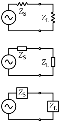
Electrical impedance
Encyclopedia

Complex number
A complex number is a number consisting of a real part and an imaginary part. Complex numbers extend the idea of the one-dimensional number line to the two-dimensional complex plane by using the number line for the real part and adding a vertical axis to plot the imaginary part...
ratio of the voltage to the current in an alternating current
Alternating current
In alternating current the movement of electric charge periodically reverses direction. In direct current , the flow of electric charge is only in one direction....
(AC) circuit. Impedance extends the concept of resistance
Electrical resistance
The electrical resistance of an electrical element is the opposition to the passage of an electric current through that element; the inverse quantity is electrical conductance, the ease at which an electric current passes. Electrical resistance shares some conceptual parallels with the mechanical...
to AC circuits, and possesses both magnitude and phase
Phase (waves)
Phase in waves is the fraction of a wave cycle which has elapsed relative to an arbitrary point.-Formula:The phase of an oscillation or wave refers to a sinusoidal function such as the following:...
, unlike resistance which has only magnitude. When a circuit is driven with direct current
Direct current
Direct current is the unidirectional flow of electric charge. Direct current is produced by such sources as batteries, thermocouples, solar cells, and commutator-type electric machines of the dynamo type. Direct current may flow in a conductor such as a wire, but can also flow through...
(DC), there is no distinction between impedance and resistance; the latter can be thought of as impedance with zero phase angle.
It is necessary to introduce the concept of impedance in AC circuits because there are other mechanisms impeding the flow of current besides the normal resistance of DC circuits. There are an additional two impeding mechanisms to be taken into account in AC circuits: the induction of voltages in conductors self-induced by the magnetic fields of currents (inductance
Inductance
In electromagnetism and electronics, inductance is the ability of an inductor to store energy in a magnetic field. Inductors generate an opposing voltage proportional to the rate of change in current in a circuit...
), and the electrostatic storage of charge induced by voltages between conductors (capacitance
Capacitance
In electromagnetism and electronics, capacitance is the ability of a capacitor to store energy in an electric field. Capacitance is also a measure of the amount of electric potential energy stored for a given electric potential. A common form of energy storage device is a parallel-plate capacitor...
). The impedance caused by these two effects is collectively referred to as reactance and forms the imaginary
Imaginary number
An imaginary number is any number whose square is a real number less than zero. When any real number is squared, the result is never negative, but the square of an imaginary number is always negative...
part of complex impedance whereas resistance forms the real
Real number
In mathematics, a real number is a value that represents a quantity along a continuum, such as -5 , 4/3 , 8.6 , √2 and π...
part.
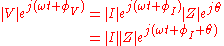
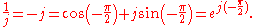
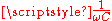
The symbol for impedance is usually
 and it may be represented by writing its magnitude and phase in the form
  . However, complex number representation is often more powerful for circuit analysis purposes. The term impedance was coined by Oliver Heaviside
Oliver Heaviside
Oliver Heaviside was a self-taught English electrical engineer, mathematician, and physicist who adapted complex numbers to the study of electrical circuits, invented mathematical techniques to the solution of differential equations , reformulated Maxwell's field equations in terms of electric and...
in July 1886. Arthur Kennelly was the first to represent impedance with complex numbers in 1893.
Impedance is defined as the frequency domain
Frequency domain
In electronics, control systems engineering, and statistics, frequency domain is a term used to describe the domain for analysis of mathematical functions or signals with respect to frequency, rather than time....
ratio of the voltage to the current. In other words, it is the voltage–current ratio for a single complex exponential at a particular frequency ω. In general, impedance will be a complex number, with the same units
Dimensional analysis
In physics and all science, dimensional analysis is a tool to find or check relations among physical quantities by using their dimensions. The dimension of a physical quantity is the combination of the basic physical dimensions which describe it; for example, speed has the dimension length per...
as resistance, for which the SI unit is the ohm
Ohm
The ohm is the SI unit of electrical resistance, named after German physicist Georg Simon Ohm.- Definition :The ohm is defined as a resistance between two points of a conductor when a constant potential difference of 1 volt, applied to these points, produces in the conductor a current of 1 ampere,...
(Ω). For a sinusoidal current or voltage input, the polar form of the complex impedance relates the amplitude and phase of the voltage and current. In particular,
- The magnitude of the complex impedance is the ratio of the voltage amplitude to the current amplitude.
- The phase of the complex impedance is the phase shift by which the current is ahead of the voltage.
The reciprocal
Multiplicative inverse
In mathematics, a multiplicative inverse or reciprocal for a number x, denoted by 1/x or x−1, is a number which when multiplied by x yields the multiplicative identity, 1. The multiplicative inverse of a fraction a/b is b/a. For the multiplicative inverse of a real number, divide 1 by the...
of impedance is admittance
Admittance
In electrical engineering, the admittance is a measure of how easily a circuit or device will allow a current to flow. It is defined as the inverse of the impedance . The SI unit of admittance is the siemens...
(i.e., admittance is the current-to-voltage ratio, and it conventionally carries units of siemens
Siemens (unit)
The siemens is the SI derived unit of electric conductance and electric admittance. Conductance and admittance are the reciprocals of resistance and impedance respectively, hence one siemens is equal to the reciprocal of one ohm, and is sometimes referred to as the mho. In English, the term...
, formerly called mhos).
Complex impedance
Impedance is represented as a complexComplex number
A complex number is a number consisting of a real part and an imaginary part. Complex numbers extend the idea of the one-dimensional number line to the two-dimensional complex plane by using the number line for the real part and adding a vertical axis to plot the imaginary part...
quantity
 and the term complex impedance may be used interchangeably; the polar form conveniently captures both magnitude and phase characteristics,
where the magnitude
 represents the ratio of the voltage difference amplitude to the current amplitude, while the argument
  gives the phase difference between voltage and current and
  is the imaginary unit
Imaginary unit
In mathematics, the imaginary unit allows the real number system ℝ to be extended to the complex number system ℂ, which in turn provides at least one root for every polynomial . The imaginary unit is denoted by , , or the Greek...
. In Cartesian form,

where the real part of impedance is the resistance
 and the imaginary part is the reactance
  .
.Where it is required to add or subtract impedances the cartesian form is more convenient, but when quantities are multiplied or divided the calculation becomes simpler if the polar form is used. A circuit calculation, such as finding the total impedance of two impedances in parallel, may require conversion between forms several times during the calculation. Conversion between the forms follows the normal conversion rules of complex numbers.
Ohm's law
The meaning of electrical impedance can be understood by substituting it into Ohm's lawOhm's law
Ohm's law states that the current through a conductor between two points is directly proportional to the potential difference across the two points...
.

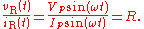
The magnitude of the impedance
 acts just like resistance, giving the drop in voltage amplitude across an impedance
  for a given current
  . The phase factor tells us that the current lags the voltage by a phase of
  (i.e. in the time domain
Time domain
Time domain is a term used to describe the analysis of mathematical functions, physical signals or time series of economic or environmental data, with respect to time. In the time domain, the signal or function's value is known for all real numbers, for the case of continuous time, or at various...
, the current signal is shifted
 later with respect to the voltage signal).
Just as impedance extends Ohm's law to cover AC circuits, other results from DC circuit analysis such as voltage division, current division, Thevenin's theorem
Thévenin's theorem
In circuit theory, Thévenin's theorem for linear electrical networks states that any combination of voltage sources, current sources, and resistors with two terminals is electrically equivalent to a single voltage source V and a single series resistor R. For single frequency AC systems the theorem...
, and Norton's theorem
Norton's theorem
Norton's theorem for linear electrical networks, known in Europe as the Mayer–Norton theorem, states that any collection of voltage sources, current sources, and resistors with two terminals is electrically equivalent to an ideal current source, I, in parallel with a single resistor, R...
, can also be extended to AC circuits by replacing resistance with impedance.
Complex voltage and current
 and
and  .
.
Impedance is defined as the ratio of these quantities.

Substituting these into Ohm's law we have
Noting that this must hold for all
 , we may equate the magnitudes and phases to obtain

The magnitude equation is the familiar Ohm's law applied to the voltage and current amplitudes, while the second equation defines the phase relationship.
Validity of complex representation
This representation using complex exponentials may be justified by noting that (by Euler's formulaEuler's formula
Euler's formula, named after Leonhard Euler, is a mathematical formula in complex analysis that establishes the deep relationship between the trigonometric functions and the complex exponential function...
):

i.e. a real-valued sinusoidal function (which may represent our voltage or current waveform) may be broken into two complex-valued functions. By the principle of superposition
Superposition principle
In physics and systems theory, the superposition principle , also known as superposition property, states that, for all linear systems, the net response at a given place and time caused by two or more stimuli is the sum of the responses which would have been caused by each stimulus individually...
, we may analyse the behaviour of the sinusoid on the left-hand side by analysing the behaviour of the two complex terms on the right-hand side. Given the symmetry, we only need to perform the analysis for one right-hand term; the results will be identical for the other. At the end of any calculation, we may return to real-valued sinusoids by further noting that

In other words, we simply take the real part of the result.
Phasors
A phasor is a constant complex number, usually expressed in exponential form, representing the complex amplitude (magnitude and phase) of a sinusoidal function of time. Phasors are used by electrical engineers to simplify computations involving sinusoids, where they can often reduce a differential equation problem to an algebraic one.The impedance of a circuit element can be defined as the ratio of the phasor voltage across the element to the phasor current through the element, as determined by the relative amplitudes and phases of the voltage and current. This is identical to the definition from Ohm's law given above, recognising that the factors of
 cancel.
Device examples
Resistor
A linear resistor is a linear, passive two-terminal electrical component that implements electrical resistance as a circuit element.The current through a resistor is in direct proportion to the voltage across the resistor's terminals. Thus, the ratio of the voltage applied across a resistor's...
is purely real and is referred to as a resistive impedance:

In this case the voltage and current waveforms are proportional and in phase.
Ideal inductor
Inductor
An inductor is a passive two-terminal electrical component used to store energy in a magnetic field. An inductor's ability to store magnetic energy is measured by its inductance, in units of henries...
s and capacitor
Capacitor
A capacitor is a passive two-terminal electrical component used to store energy in an electric field. The forms of practical capacitors vary widely, but all contain at least two electrical conductors separated by a dielectric ; for example, one common construction consists of metal foils separated...
s have a purely imaginary
Imaginary number
An imaginary number is any number whose square is a real number less than zero. When any real number is squared, the result is never negative, but the square of an imaginary number is always negative...
reactive impedance:

the impedance of inductors increases with frequency;

the impedance of capacitors decreases with frequency.
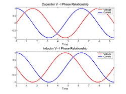
In both cases, for an applied sinusoidal voltage, the resulting current is also sinusoidal, but in quadrature, 90 degrees out of phase with the voltage. However the phases have opposite signs: in an inductor, the current is lagging; in a capacitor the current is leading.
Note the following identities for the imaginary unit and its reciprocal:
Thus we can rewrite the inductor and capacitor impedance equations in polar form:


The magnitude tells us the change in voltage amplitude for a given current amplitude
through the impedance, while the exponential factors give the phase relationship.
Deriving the device specific impedances
What follows below is a derivation of impedance for each of the three basic circuitElectrical network
An electrical network is an interconnection of electrical elements such as resistors, inductors, capacitors, transmission lines, voltage sources, current sources and switches. An electrical circuit is a special type of network, one that has a closed loop giving a return path for the current...
elements, the resistor, the capacitor, and the inductor. Although the idea can be extended to define the relationship between the voltage and current of any arbitrary signal
Signal (electrical engineering)
In the fields of communications, signal processing, and in electrical engineering more generally, a signal is any time-varying or spatial-varying quantity....
, these derivations will assume sinusoidal signals, since any arbitrary signal can be approximated as a sum of sinusoids through Fourier Analysis.
Resistor
For a resistor, we have the relation:
This is simply a statement of Ohm's Law
Ohm's law
Ohm's law states that the current through a conductor between two points is directly proportional to the potential difference across the two points...
.
Considering the voltage signal to be

it follows that
This tells us that the ratio of AC voltage amplitude to AC current amplitude across a resistor is
 , and that the AC voltage leads the AC current across a resistor by 0 degrees.
This result is commonly expressed as

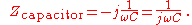
Capacitor
For a capacitor, we have the relation: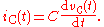
Considering the voltage signal to be

it follows that
And thus
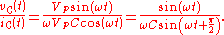
This tells us that the ratio of AC voltage amplitude to AC current amplitude across a capacitor is
 , and that the AC voltage lags the AC current across a capacitor by 90 degrees (or the AC current leads the AC voltage across a capacitor by 90 degrees).
This result is commonly expressed in polar form, as
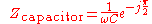
or, by applying Euler's formula, as
Inductor
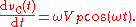
For the inductor, we have the relation:
This time, considering the current signal to be

it follows that
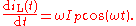
And thus
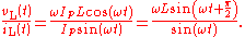
This tells us that the ratio of AC voltage amplitude to AC current amplitude across an inductor is
 , and that the AC voltage leads the AC current across an inductor by 90 degrees.
This result is commonly expressed in polar form, as

Or, more simply, using Euler's formula, as

Generalised s-plane impedance
Impedance defined in terms of jω can strictly only be applied to circuits which are energised with a steady-state AC signal. The concept of impedance can be extended to a circuit energised with any arbitrary signal by using complex frequency instead of jω. Complex frequency is given the symbol s and is, in general, a complex number. Signals are expressed in terms of complex frequency by taking the Laplace transform of the time domainTime domain
Time domain is a term used to describe the analysis of mathematical functions, physical signals or time series of economic or environmental data, with respect to time. In the time domain, the signal or function's value is known for all real numbers, for the case of continuous time, or at various...
expression of the signal. The impedance of the basic circuit elements in this more general notation is as follows:
| Element | Impedance expression |
|---|---|
| Resistor |  |
| Inductor |  |
| Capacitor |  |
For a DC circuit this simplifies to . For a steady-state sinusoidal AC signal .
Resistance vs reactance
Resistance and reactance together determine the magnitude and phase of the impedance through the following relations:

In many applications the relative phase of the voltage and current is not critical so only the magnitude of the impedance is significant.
Resistance
Resistance is the real part of impedance; a device with a purely resistive impedance exhibits no phase shift between the voltage and current.
Reactance
Reactance is the imaginary part of the impedance; a component with a finite reactance induces a phase shift
  between the voltage across it and the current through it.
A purely reactive component is distinguished by the fact that the sinusoidal voltage across the component is in quadrature with the sinusoidal current through the component. This implies that the component alternately absorbs energy from the circuit and then returns energy to the circuit. A pure reactance will not dissipate any power.
Capacitive reactance
A capacitor has a purely reactive impedance which is inversely proportional to the signal frequencyFrequency
Frequency is the number of occurrences of a repeating event per unit time. It is also referred to as temporal frequency.The period is the duration of one cycle in a repeating event, so the period is the reciprocal of the frequency...
. A capacitor consists of two conductors separated by an insulator
Electrical insulation
thumb|250px|[[Coaxial Cable]] with dielectric insulator supporting a central coreThis article refers to electrical insulation. For insulation of heat, see Thermal insulation...
, also known as a dielectric
Dielectric
A dielectric is an electrical insulator that can be polarized by an applied electric field. When a dielectric is placed in an electric field, electric charges do not flow through the material, as in a conductor, but only slightly shift from their average equilibrium positions causing dielectric...
.

At low frequencies a capacitor is open circuit
Open circuit
The term Open circuit may refer to:*Open-circuit scuba, a type of SCUBA-diving equipment where the user breathes from the set and then exhales to the surroundings without recycling the exhaled air...
, as no charge flows in the dielectric. A DC voltage applied across a capacitor causes charge to accumulate on one side; the electric field
Electric field
In physics, an electric field surrounds electrically charged particles and time-varying magnetic fields. The electric field depicts the force exerted on other electrically charged objects by the electrically charged particle the field is surrounding...
due to the accumulated charge is the source of the opposition to the current. When the potential
Potential
*In linguistics, the potential mood*The mathematical study of potentials is known as potential theory; it is the study of harmonic functions on manifolds...
associated with the charge exactly balances the applied voltage, the current goes to zero.
Driven by an AC supply, a capacitor will only accumulate a limited amount of charge before the potential difference changes sign and the charge dissipates. The higher the frequency, the less charge will accumulate and the smaller the opposition to the current.
Inductive reactance
Inductive reactance is proportional
Proportionality (mathematics)
In mathematics, two variable quantities are proportional if one of them is always the product of the other and a constant quantity, called the coefficient of proportionality or proportionality constant. In other words, are proportional if the ratio \tfrac yx is constant. We also say that one...
to the signal frequency
Frequency
Frequency is the number of occurrences of a repeating event per unit time. It is also referred to as temporal frequency.The period is the duration of one cycle in a repeating event, so the period is the reciprocal of the frequency...
 and the inductance
Inductance
In electromagnetism and electronics, inductance is the ability of an inductor to store energy in a magnetic field. Inductors generate an opposing voltage proportional to the rate of change in current in a circuit...
 .
.
An inductor consists of a coiled conductor. Faraday's law
Faraday's law of induction
Faraday's law of induction dates from the 1830s, and is a basic law of electromagnetism relating to the operating principles of transformers, inductors, and many types of electrical motors and generators...
of electromagnetic induction gives the back emf
Electromotive force
In physics, electromotive force, emf , or electromotance refers to voltage generated by a battery or by the magnetic force according to Faraday's Law, which states that a time varying magnetic field will induce an electric current.It is important to note that the electromotive "force" is not a...
 (voltage opposing current) due to a rate-of-change of magnetic flux density
  through a current loop.
For an inductor consisting of a coil with
 loops this gives.
The back-emf is the source of the opposition to current flow. A constant direct current
Direct current
Direct current is the unidirectional flow of electric charge. Direct current is produced by such sources as batteries, thermocouples, solar cells, and commutator-type electric machines of the dynamo type. Direct current may flow in a conductor such as a wire, but can also flow through...
has a zero rate-of-change, and sees an inductor as a short-circuit (it is typically made from a material with a low resistivity
Resistivity
Electrical resistivity is a measure of how strongly a material opposes the flow of electric current. A low resistivity indicates a material that readily allows the movement of electric charge. The SI unit of electrical resistivity is the ohm metre...
). An alternating current
Alternating current
In alternating current the movement of electric charge periodically reverses direction. In direct current , the flow of electric charge is only in one direction....
has a time-averaged rate-of-change that is proportional to frequency, this causes the increase in inductive reactance with frequency.
Combining impedances
The total impedance of many simple networks of components can be calculated using the rules for combining impedances in series and parallel. The rules are identical to those used for combining resistances, except that the numbers in general will be complex numbers. In the general case however, equivalent impedance transformsEquivalent impedance transforms
An equivalent impedance is an equivalent circuit of an electrical network of impedance elements which presents the same impedance between all pairs of terminals as did the given network...
in addition to series and parallel will be required.
Series combination
For components connected in series, the current through each circuit element is the same; the total impedance is simply the sum of the component impedances.

Or explicitly in real and imaginary terms:

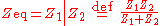
Parallel combination
For components connected in parallel, the voltage across each circuit element is the same; the ratio of currents through any two elements is the inverse ratio of their impedances.
Hence the inverse total impedance is the sum of the inverses of the component impedances:
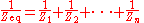
or, when n = 2:
The equivalent impedance
 can be calculated in terms of the equivalent resistance
  and reactance
  .
.


Measurement
The impedance of a device can be calculated by complex division of the voltage and current. The impedance of the device can be calculated by applying a sinusoidal voltage to the device in series with a resistor, and measuring the voltage across the resistor and across the device. Performing this measurement by sweeping the frequencies of the applied signal provides the impedance phase and magnitude.Impulse impedance spectroscopy
The use of an impulse response may be used in combination with the fast Fourier transformFast Fourier transform
A fast Fourier transform is an efficient algorithm to compute the discrete Fourier transform and its inverse. "The FFT has been called the most important numerical algorithm of our lifetime ." There are many distinct FFT algorithms involving a wide range of mathematics, from simple...
(FFT) to rapidly measure the electrical impedance of various electrical devices. The technique compares well to other methodologies such as network and impedance analyzers while providing additional versatility in the electrical impedance measurement. The technique is theoretically simple, easy to
implement and completed with ordinary laboratory instrumentation for minimal cost.
Variable impedance
In general, neither impedance nor admittance can be time varying as they are defined for complex exponentials for –∞ < t < +∞. If the complex exponential voltage–current ratio changes over time or amplitude, the circuit element cannot be described using the frequency domain. However, many systems (e.g., varicapVaricap
In electronics, a varicap diode, varactor diode, variable capacitance diode, variable reactance diode or tuning diode is a type of diode which has a variable capacitance that is a function of the voltage impressed on its terminals....
s that are used in radio tuners
Tuner (radio)
A radio tuner is a subsystem that receives radio broadcasts and converts them into audio-frequency signals which can be fed into an amplifier driving a loudspeaker. FM tuner, AM tuner, Digital Audio Broadcasting DAB tuner, etc. are types of radio tuner dealing with transmissions using different...
) may exhibit non-linear or time-varying voltage–current ratios that appear to be LTI
LTI system theory
Linear time-invariant system theory, commonly known as LTI system theory, comes from applied mathematics and has direct applications in NMR spectroscopy, seismology, circuits, signal processing, control theory, and other technical areas. It investigates the response of a linear and time-invariant...
for small signals over small observation windows; hence, they can be roughly described as having a time-varying impedance. That is, this description is an approximation; over large signal swings or observation windows, the voltage–current relationship is non-LTI and cannot be described by impedance.
See also
- Impedance matchingImpedance matchingIn electronics, impedance matching is the practice of designing the input impedance of an electrical load to maximize the power transfer and/or minimize reflections from the load....
- Impedance cardiographyImpedance cardiographyImpedance cardiography is a plethysmography technique of using sensors to detect the properties of the blood flow in the thorax.-Introduction:...
- Impedance bridgingImpedance bridgingIn electronics, especially audio and sound recording, a high impedance bridging, voltage bridging, or simply bridging connection is one which maximizes transfer of a voltage signal to the load...
- Characteristic impedanceCharacteristic impedanceThe characteristic impedance or surge impedance of a uniform transmission line, usually written Z_0, is the ratio of the amplitudes of a single pair of voltage and current waves propagating along the line in the absence of reflections. The SI unit of characteristic impedance is the ohm...
- Negative impedance converterNegative impedance converterThe negative impedance converter is a one-port op-amp circuit acting as a negative load which injects energy into circuits in contrast to an ordinary load that consumes energy from them. This is achieved by adding or subtracting excessive varying voltage in series to the voltage drop across an...
- ImmittanceImmittanceImmittance in electrical and acoustical terminology is a concept combining the impedance and admittance of a system or circuit. The term was invented by Bode....
External links
- Explaining Impedance
- Antenna Impedance
- ECE 209: Review of Circuits as LTI Systems – Brief explanation of Laplace-domain circuit analysis; includes a definition of impedance.