

Equivalent impedance transforms
Encyclopedia
An equivalent impedance is an equivalent circuit
of an electrical network
of impedance
elements which presents the same impedance between all pairs of terminals as did the given network. This article describes mathematical transformations between some passive
, linear
impedance networks commonly found in electronic circuits.
There are a number of very well known and often used equivalent circuits in linear network analysis
. These include resistors in series, resistors in parallel and the extension to series and parallel circuits
for capacitor
s, inductor
s and general impedances. Also well known are the Norton
and Thévenin
equivalent current generator and voltage generator circuits respectively, as is the Y-Δ transform. None of these are discussed in detail here; the individual linked articles should be consulted.
The number of equivalent circuits that a linear network can be transformed into is unbounded. Even in the most trivial cases this can be seen to be true, for instance, by asking how many different combinations of resistors in parallel are equivalent to a given combined resistor. This article could never hope to be comprehensive, but there are some generalisations possible. Wilhelm Cauer
found a transformation that could generate all possible equivalents of a given rational, passive, linear one-port, or in other words, any given two-terminal impedance. Transformations of 4-terminal, especially 2-port, networks
are also commonly found and transformations of yet more complex networks are possible.
The vast scale of the topic of equivalent circuits is underscored in a story told by Sidney Darlington
. According to Darlington, a large number of equivalent circuits were found by Ronald Foster, following his and George Campbell's
1920 paper on non-dissipative four-ports. In the course of this work they looked at the ways four ports could be interconnected with ideal transformers. They found a number of combinations which might have practical applications and asked the AT&T patent department to have them patented. The patent department replied that it was pointless just patenting some of the circuits if a competitor could use an equivalent circuit to get around the patent; they should patent all of them or not bother. Foster therefore set to work calculating every last one of them. He arrived at an enormous total of 83,539 equivalents. This was too many to patent, so instead the information was released into the public domain in order to prevent any of AT&T's competitors from patenting them in the future.
designers favour RC-kind networks because inductor
s are less easy to manufacture. Transformations are simpler and easier to find than for 3-element-kind networks. One-element-kind networks can be thought of as a special case of two-element-kind. It is possible to use the transformations in this section on a certain few 3-element-kind networks by substituting a network of elements for element Zn. However, this is limited to a maximum of two impedances being substituted; the remainder will not be a free choice. All the transformation equations given in this section are due to Otto Zobel.
. Equivalence is proved between two networks by directly comparing the two sets of equations and equating coefficient
s. For large networks more powerful techniques are required. A common approach is to start by expressing the network of impedances as a matrix
. This approach is only good for rational networks. Any network that includes distributed elements
, such as a transmission line
, cannot be represented by a finite matrix. Generally, an n-mesh network requires an nxn matrix to represent it. For instance the matrix for a 3-mesh network might look like;
The entries of the matrix are chosen so that the matrix forms a system of linear equation
s in the mesh voltages and currents (as defined for mesh analysis
);

The example diagram in Figure 1, for instance, can be represented as an impedance matrix by;
and the associated system of linear equations are,
In the most general case, each branch, Zp, of the network may be made up of three elements so that,
This is the conventional way of representing a general impedance but for the purposes of this article it is mathematically more convenient to deal with elastance, D, the inverse of capacitance, C. In those terms the general branch impedance can be represented by,

Likewise, each entry of the impedance matrix can consist of the sum of three elements. Consequently, the matrix can be decomposed into three nxn matrices, one for each of the three element kinds;

It is desired that the matrix [Z] represent an impedance, Z(s). For this purpose, the loop of one of the meshes is cut and Z(s) is the impedance measured between the points so cut. It is conventional to assume the external connection port is in mesh 1, and is therefore connected across matrix entry Z11, although it would be perfectly possible to formulate this with connections to any desired nodes. In the following discussion Z(s) taken across Z11 is assumed. Z(s) may be calculated from [Z] by;

For the example network above;

 and,
and,
This result is easily verified to be correct by the more direct method of resistors in series and parallel. However, such methods rapidly become tedious and cumbersome with the growth of the size and complexity of the network under analysis.
The entries of [R], [L] and [D] cannot be set arbitrarily. For [Z] to be able to realise the impedance Z(s) then [R],[L] and [D] must all be positive-definite matrices
. Even then, the realisation of Z(s) will, in general, contain ideal transformers within the network. Finding only those transforms that do not require mutual inductances or ideal transformers is a more difficult task. Similarly, if starting from the "other end" and specifying an expression for Z(s), this again cannot be done arbitrarily. To be realisable as a rational impedance, Z(s) must be positive-real. The positive-real (PR) condition is both necessary and sufficient but there may be practical reasons for rejecting some topologies
.
A general impedance transform for finding equivalent rational one-ports from a given instance of [Z] is due to Wilhelm Cauer
. The group of real affine transformation
s,
is invariant in Z(s). That is, all the transformed networks are equivalents according to the definition given here. If the Z(s) for the initial given matrix is realisable, that is, it meets the PR condition, then all the transformed networks produced by this transformation will also meet the PR condition.
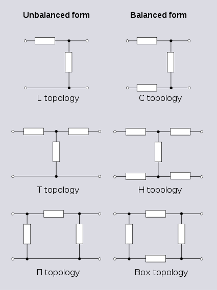 A 3-terminal network can also be used as a 2-port. To achieve this, one of the terminals is connected in common to one terminal of both ports. In other words, one terminal has been split into two terminals and the network has effectively been converted to a 4-terminal network. This topology is known as unbalanced
topology and is opposed to balanced topology. Balanced topology requires, referring to Figure 3, that the impedance measured between terminals 1 and 3 is equal to the impedance measured between 2 and 4. This is the pairs of terminals not forming ports: the case where the pairs of terminals forming ports have equal impedance is referred to as symmetrical. Strictly speaking, any network that does not meet the balance condition is unbalanced, but the term is most often referring to the 3-terminal topology described above and in Figure 3. Transforming an unbalanced 2-port network into a balanced network is usually quite straightforward: all series connected elements are divided in half with one half being relocated in what was the common branch. Transforming from balanced to unbalanced topology will often be possible with the reverse transformation but there are certain cases of certain topologies which cannot be transformed in this way. For example, see the discussion of lattice transforms below.
An example of a 3-terminal network transform that is not restricted to 2-ports is the Y-Δ transform. This is a particularly important transform for finding equivalent impedances. Its importance arises from the fact that the total impedance between two terminals cannot be determined solely by calculating series and parallel combinations except for a certain restricted class of network. In the general case additional transformations are required. The Y-Δ transform, its inverse the Δ-Y transform, and the n-terminal analogues of these two transforms (star-polygon transforms) represent the minimal additional transforms required to solve the general case. Series and parallel are, in fact, the 2-terminal versions of star and polygon topology. A common simple topology that cannot be solved by series and parallel combinations is the input impedance to a bridge network (except in the special case when the bridge is in balance). The rest of the transforms in this section are all restricted to use with 2-ports only.
. The method is limited to symmetric networks but this includes many topologies commonly found in filters, attenuators
and equalisers. The lattice topology is intrinsically balanced, there is no unbalanced counterpart to the lattice and it will usually require more components than the transformed network.
Reverse transformations from a lattice to an unbalanced topology are not always possible in terms of passive components. For instance, this transform,
cannot be realised with passive components because of the negative values arising in the transformed circuit. It can however be realised if mutual inductances and ideal transformers are permitted, for instance, in this circuit. Another possibility is to permit the use of active components which would enable negative impedances
to be directly realised as circuit components.
It can sometimes be useful to make such a transformation, not for the purposes of actually building the transformed circuit, but rather, for the purposes of aiding understanding of how the original circuit is working. The following circuit in bridged-T topology is a modification of a mid-series m-derived filter
T-section. The circuit is due to Hendrik Bode who claims that the addition of the bridging resistor of a suitable value will cancel the parasitic resistance of the shunt inductor. The action of this circuit is clear if it is transformed into T topology - in this form there is a negative resistance in the shunt branch which can be made to be exactly equal to the positive parasitic resistance of the inductor.
Any symmetrical network can be transformed into any other symmetrical network by the same method, that is, by first transforming into the intermediate lattice form (omitted for clarity from the above example transform) and from the lattice form into the required target form. As with the example, this will generally result in negative elements except in special cases.
states that any PR function Z(s) can be realised as a lossless two-port terminated in a positive resistor R. That is, regardless of how many resistors feature in the matrix [Z] representing the impedance network, a transform can be found that will realise the network entirely as an LC-kind network with just one resistor across the output port (which would normally represent the load). No resistors within the network are necessary in order to realise the specified response. Consequently, it is always possible to reduce 3-element-kind 2-port networks to 2-element-kind (LC) 2-port networks provided the output port is terminated in a resistance of the required value.
These transforms do not just apply to single elements; entire networks can be passed through the transformer. In this manner, the transformer can be shifted around the network to a more convenient location. Darlington gives an equivalent transform that can eliminate an ideal transformer altogether. This technique requires that the transformer is next to (or capable of being moved next to) an "L" network of same-kind impedances. The transform in all variants results in the "L" network facing the opposite way, that is, topologically mirrored.
Example 3 shows the result is a Π-network rather than an L-network. The reason for this is that the shunt element has more capacitance than is required by the transform so some is still left over after applying the transform. If the excess were instead, in the element nearest the transformer, this could be dealt with by first shifting the excess to the other side of the transformer before carrying out the transform.
Equivalent circuit
In electrical engineering and science, an equivalent circuit refers to a theoretical circuit that retains all of the electrical characteristics of a given circuit. Often, an equivalent circuit is sought that is the simplest form of a more complex circuit in order to aid analysis. In its most common...
of an electrical network
Electrical network
An electrical network is an interconnection of electrical elements such as resistors, inductors, capacitors, transmission lines, voltage sources, current sources and switches. An electrical circuit is a special type of network, one that has a closed loop giving a return path for the current...
of impedance
Electrical impedance
Electrical impedance, or simply impedance, is the measure of the opposition that an electrical circuit presents to the passage of a current when a voltage is applied. In quantitative terms, it is the complex ratio of the voltage to the current in an alternating current circuit...
elements which presents the same impedance between all pairs of terminals as did the given network. This article describes mathematical transformations between some passive
Passivity (engineering)
Passivity is a property of engineering systems, used in a variety of engineering disciplines, but most commonly found in analog electronics and control systems...
, linear
Linear
In mathematics, a linear map or function f is a function which satisfies the following two properties:* Additivity : f = f + f...
impedance networks commonly found in electronic circuits.
There are a number of very well known and often used equivalent circuits in linear network analysis
Network analysis (electrical circuits)
A network, in the context of electronics, is a collection of interconnected components. Network analysis is the process of finding the voltages across, and the currents through, every component in the network. There are a number of different techniques for achieving this...
. These include resistors in series, resistors in parallel and the extension to series and parallel circuits
Series and parallel circuits
Components of an electrical circuit or electronic circuit can be connected in many different ways. The two simplest of these are called series and parallel and occur very frequently. Components connected in series are connected along a single path, so the same current flows through all of the...
for capacitor
Capacitor
A capacitor is a passive two-terminal electrical component used to store energy in an electric field. The forms of practical capacitors vary widely, but all contain at least two electrical conductors separated by a dielectric ; for example, one common construction consists of metal foils separated...
s, inductor
Inductor
An inductor is a passive two-terminal electrical component used to store energy in a magnetic field. An inductor's ability to store magnetic energy is measured by its inductance, in units of henries...
s and general impedances. Also well known are the Norton
Norton's theorem
Norton's theorem for linear electrical networks, known in Europe as the Mayer–Norton theorem, states that any collection of voltage sources, current sources, and resistors with two terminals is electrically equivalent to an ideal current source, I, in parallel with a single resistor, R...
and Thévenin
Thévenin's theorem
In circuit theory, Thévenin's theorem for linear electrical networks states that any combination of voltage sources, current sources, and resistors with two terminals is electrically equivalent to a single voltage source V and a single series resistor R. For single frequency AC systems the theorem...
equivalent current generator and voltage generator circuits respectively, as is the Y-Δ transform. None of these are discussed in detail here; the individual linked articles should be consulted.
The number of equivalent circuits that a linear network can be transformed into is unbounded. Even in the most trivial cases this can be seen to be true, for instance, by asking how many different combinations of resistors in parallel are equivalent to a given combined resistor. This article could never hope to be comprehensive, but there are some generalisations possible. Wilhelm Cauer
Wilhelm Cauer
Wilhelm Cauer was a German mathematician and scientist. He is most noted for his work on the analysis and synthesis of electrical filters and his work marked the beginning of the field of network synthesis...
found a transformation that could generate all possible equivalents of a given rational, passive, linear one-port, or in other words, any given two-terminal impedance. Transformations of 4-terminal, especially 2-port, networks
Two-port network
A two-port network is an electrical circuit or device with two pairs of terminals connected together internally by an electrical network...
are also commonly found and transformations of yet more complex networks are possible.
The vast scale of the topic of equivalent circuits is underscored in a story told by Sidney Darlington
Sidney Darlington
Sidney Darlington was an electrical engineer and inventor of a transistor configuration in 1953, the Darlington pair...
. According to Darlington, a large number of equivalent circuits were found by Ronald Foster, following his and George Campbell's
George Ashley Campbell
George Ashley Campbell was a pioneer in developing and applying quantitative mathematical methods to the problems of long-distance telegraphy and telephony. His most important contributions were to the theory and implementation of the use of loading coils and the first wave filters designed to...
1920 paper on non-dissipative four-ports. In the course of this work they looked at the ways four ports could be interconnected with ideal transformers. They found a number of combinations which might have practical applications and asked the AT&T patent department to have them patented. The patent department replied that it was pointless just patenting some of the circuits if a competitor could use an equivalent circuit to get around the patent; they should patent all of them or not bother. Foster therefore set to work calculating every last one of them. He arrived at an enormous total of 83,539 equivalents. This was too many to patent, so instead the information was released into the public domain in order to prevent any of AT&T's competitors from patenting them in the future.
2-terminal, 2-element-kind networks
A single impedance has two terminals to connect to the outside world, hence can be described as a 2-terminal, or a one-port, network. Despite the simple description, there is no limit to the number of meshes, and hence complexity and number of elements, that the impedance network may have. 2-element-kind networks are common in circuit design; filters, for instance, are often LC-kind networks and printed circuitPrinted circuit board
A printed circuit board, or PCB, is used to mechanically support and electrically connect electronic components using conductive pathways, tracks or signal traces etched from copper sheets laminated onto a non-conductive substrate. It is also referred to as printed wiring board or etched wiring...
designers favour RC-kind networks because inductor
Inductor
An inductor is a passive two-terminal electrical component used to store energy in a magnetic field. An inductor's ability to store magnetic energy is measured by its inductance, in units of henries...
s are less easy to manufacture. Transformations are simpler and easier to find than for 3-element-kind networks. One-element-kind networks can be thought of as a special case of two-element-kind. It is possible to use the transformations in this section on a certain few 3-element-kind networks by substituting a network of elements for element Zn. However, this is limited to a maximum of two impedances being substituted; the remainder will not be a free choice. All the transformation equations given in this section are due to Otto Zobel.
3-element networks
One-element networks are trivial and two-element, two-terminal networks are either two elements in series or two elements in parallel, also trivial. The smallest number of elements that is non-trivial is three, and there are two 2-element-kind non-trivial transformations possible, one being both the reverse transformation and the topological dual, of the other.| Description | Network | Transform equations | Transformed network |
|---|---|---|---|
| Transform 1.1 Transform 1.2 is the reverse of this transform. |
   |
||
| Transform 1.2 The reverse transform, and topological dual, of Transform 1.1. |
tyle="line-height:400%;"|   |
||
| Example 1. An example of Transform 1.2. The reduced size of the inductor has practical advantages. |
    |
4-element networks
There are four non-trivial 4-element transformations for 2-element-kind networks. Two of these are the reverse transformations of the other two and two are the dual of a different two. Further transformations are possible in the special case of Z2 being made the same element kind as Z1, that is, when the network is reduced to one-element-kind. The number of possible networks continues to grow as the number of elements is increased. For all entries in the following table it is defined: , , , , , , |
 , , . . |
| Description | Network | Transform equations | Transformed network |
|---|---|---|---|
| Transform 2.1 Transform 2.2 is the reverse of this transform. Transform 2.3 is the topological dual of this transform. |
    |
||
| Transform 2.2 Transform 2.1 is the reverse of this transform. Transform 2.4 is the topological dual of this transform. |
    |
||
| Transform 2.3 Transform 2.4 is the reverse of this transform. Transform 2.1 is the topological dual of this transform. |
    |
||
| Transform 2.4 Transform 2.3 is the reverse of this transform. Transform 2.2 is the topological dual of this transform. |
    |
||
| Example 2. An example of Transform 2.2. |
       |
2-terminal, n-element, 3-element-kind networks
Simple networks with just a few elements can be dealt with by formulating the network equations "by hand" with the application of simple network theorems such as Kirchhoff's lawsKirchhoff's circuit laws
Kirchhoff's circuit laws are two equalities that deal with the conservation of charge and energy in electrical circuits, and were first described in 1845 by Gustav Kirchhoff...
. Equivalence is proved between two networks by directly comparing the two sets of equations and equating coefficient
Coefficient
In mathematics, a coefficient is a multiplicative factor in some term of an expression ; it is usually a number, but in any case does not involve any variables of the expression...
s. For large networks more powerful techniques are required. A common approach is to start by expressing the network of impedances as a matrix
Matrix (mathematics)
In mathematics, a matrix is a rectangular array of numbers, symbols, or expressions. The individual items in a matrix are called its elements or entries. An example of a matrix with six elements isMatrices of the same size can be added or subtracted element by element...
. This approach is only good for rational networks. Any network that includes distributed elements
Distributed element model
In electrical engineering, the distributed element model or transmission line model of electrical circuits assumes that the attributes of the circuit are distributed continuously throughout the material of the circuit...
, such as a transmission line
Transmission line
In communications and electronic engineering, a transmission line is a specialized cable designed to carry alternating current of radio frequency, that is, currents with a frequency high enough that its wave nature must be taken into account...
, cannot be represented by a finite matrix. Generally, an n-mesh network requires an nxn matrix to represent it. For instance the matrix for a 3-mesh network might look like;
The entries of the matrix are chosen so that the matrix forms a system of linear equation
Linear equation
A linear equation is an algebraic equation in which each term is either a constant or the product of a constant and a single variable....
s in the mesh voltages and currents (as defined for mesh analysis
Mesh analysis
Mesh analysis is a method that is used to solve planar circuits for the currents at any place in the circuit. Planar circuits are circuits that can be drawn on a plane surface with no wires crossing each other. A more general technique, called loop analysis can be applied to any circuit, planar...
);
The example diagram in Figure 1, for instance, can be represented as an impedance matrix by;
and the associated system of linear equations are,
In the most general case, each branch, Zp, of the network may be made up of three elements so that,
- where L, R and C represent inductanceInductanceIn electromagnetism and electronics, inductance is the ability of an inductor to store energy in a magnetic field. Inductors generate an opposing voltage proportional to the rate of change in current in a circuit...
, resistanceElectrical resistanceThe electrical resistance of an electrical element is the opposition to the passage of an electric current through that element; the inverse quantity is electrical conductance, the ease at which an electric current passes. Electrical resistance shares some conceptual parallels with the mechanical...
, and capacitanceCapacitanceIn electromagnetism and electronics, capacitance is the ability of a capacitor to store energy in an electric field. Capacitance is also a measure of the amount of electric potential energy stored for a given electric potential. A common form of energy storage device is a parallel-plate capacitor...
respectively and s is the complex frequency operator .
.
This is the conventional way of representing a general impedance but for the purposes of this article it is mathematically more convenient to deal with elastance, D, the inverse of capacitance, C. In those terms the general branch impedance can be represented by,
Likewise, each entry of the impedance matrix can consist of the sum of three elements. Consequently, the matrix can be decomposed into three nxn matrices, one for each of the three element kinds;
It is desired that the matrix [Z] represent an impedance, Z(s). For this purpose, the loop of one of the meshes is cut and Z(s) is the impedance measured between the points so cut. It is conventional to assume the external connection port is in mesh 1, and is therefore connected across matrix entry Z11, although it would be perfectly possible to formulate this with connections to any desired nodes. In the following discussion Z(s) taken across Z11 is assumed. Z(s) may be calculated from [Z] by;
- where z11 is the complement of Z11 and |Z| is the determinantDeterminantIn linear algebra, the determinant is a value associated with a square matrix. It can be computed from the entries of the matrix by a specific arithmetic expression, while other ways to determine its value exist as well...
of [Z].
For the example network above;
and,This result is easily verified to be correct by the more direct method of resistors in series and parallel. However, such methods rapidly become tedious and cumbersome with the growth of the size and complexity of the network under analysis.
The entries of [R], [L] and [D] cannot be set arbitrarily. For [Z] to be able to realise the impedance Z(s) then [R],[L] and [D] must all be positive-definite matrices
Positive-definite matrix
In linear algebra, a positive-definite matrix is a matrix that in many ways is analogous to a positive real number. The notion is closely related to a positive-definite symmetric bilinear form ....
. Even then, the realisation of Z(s) will, in general, contain ideal transformers within the network. Finding only those transforms that do not require mutual inductances or ideal transformers is a more difficult task. Similarly, if starting from the "other end" and specifying an expression for Z(s), this again cannot be done arbitrarily. To be realisable as a rational impedance, Z(s) must be positive-real. The positive-real (PR) condition is both necessary and sufficient but there may be practical reasons for rejecting some topologies
Topology (electronics)
The topology of an electronic circuit is the form taken by the network of interconnections of the circuit components. Different specific values or ratings of the components are regarded as being the same topology....
.
A general impedance transform for finding equivalent rational one-ports from a given instance of [Z] is due to Wilhelm Cauer
Wilhelm Cauer
Wilhelm Cauer was a German mathematician and scientist. He is most noted for his work on the analysis and synthesis of electrical filters and his work marked the beginning of the field of network synthesis...
. The group of real affine transformation
Affine transformation
In geometry, an affine transformation or affine map or an affinity is a transformation which preserves straight lines. It is the most general class of transformations with this property...
s,
- where,
is invariant in Z(s). That is, all the transformed networks are equivalents according to the definition given here. If the Z(s) for the initial given matrix is realisable, that is, it meets the PR condition, then all the transformed networks produced by this transformation will also meet the PR condition.
3 and 4-terminal networks
When discussing 4-terminal networks, network analysis often proceeds in terms of 2-port networks, which covers a vast array of practically useful circuits. "2-port", in essence, refers to the way the network has been connected to the outside world: that the terminals have been connected in pairs to a source or load. It is possible to take exactly the same network and connect it to external circuitry in such a way that it is no longer behaving as a 2-port. This idea is demonstrated in Figure 2.Unbalanced
Unbalanced may refer to:* Unbalanced line or network in electrical circuits, where the impedance of the two conductor paths are not equal* An unbalanced formation in American football* Unbalanced chemical equations...
topology and is opposed to balanced topology. Balanced topology requires, referring to Figure 3, that the impedance measured between terminals 1 and 3 is equal to the impedance measured between 2 and 4. This is the pairs of terminals not forming ports: the case where the pairs of terminals forming ports have equal impedance is referred to as symmetrical. Strictly speaking, any network that does not meet the balance condition is unbalanced, but the term is most often referring to the 3-terminal topology described above and in Figure 3. Transforming an unbalanced 2-port network into a balanced network is usually quite straightforward: all series connected elements are divided in half with one half being relocated in what was the common branch. Transforming from balanced to unbalanced topology will often be possible with the reverse transformation but there are certain cases of certain topologies which cannot be transformed in this way. For example, see the discussion of lattice transforms below.
An example of a 3-terminal network transform that is not restricted to 2-ports is the Y-Δ transform. This is a particularly important transform for finding equivalent impedances. Its importance arises from the fact that the total impedance between two terminals cannot be determined solely by calculating series and parallel combinations except for a certain restricted class of network. In the general case additional transformations are required. The Y-Δ transform, its inverse the Δ-Y transform, and the n-terminal analogues of these two transforms (star-polygon transforms) represent the minimal additional transforms required to solve the general case. Series and parallel are, in fact, the 2-terminal versions of star and polygon topology. A common simple topology that cannot be solved by series and parallel combinations is the input impedance to a bridge network (except in the special case when the bridge is in balance). The rest of the transforms in this section are all restricted to use with 2-ports only.
Lattice transforms
Symmetric 2-port networks can be transformed into lattice networks using Bartlett's bisection theoremBartlett's bisection theorem
Bartlett's Bisection Theorem is an electrical theorem in network analysis due to Albert Charles Bartlett. The theorem shows that any symmetrical two-port network can be transformed into a lattice network...
. The method is limited to symmetric networks but this includes many topologies commonly found in filters, attenuators
Attenuator (electronics)
An attenuator is an electronic device that reduces the amplitude or power of a signal without appreciably distorting its waveform.An attenuator is effectively the opposite of an amplifier, though the two work by different methods...
and equalisers. The lattice topology is intrinsically balanced, there is no unbalanced counterpart to the lattice and it will usually require more components than the transformed network.
| Some common networks transformed to lattices (X-networks) | |||
|---|---|---|---|
| Description | Network | Transform equations | Transformed network |
| Transform 3.1 Transform of T network to lattice network. |
  |
||
| Transform 3.2 Transform of Π network to lattice network. |
  |
||
| Transform 3.3 Transform of Bridged-T network to lattice network. |
  |
Reverse transformations from a lattice to an unbalanced topology are not always possible in terms of passive components. For instance, this transform,
| Description | Network | Transformed network |
|---|---|---|
| Transform 3.4 Transform of a lattice phase equaliser to a T network. |
cannot be realised with passive components because of the negative values arising in the transformed circuit. It can however be realised if mutual inductances and ideal transformers are permitted, for instance, in this circuit. Another possibility is to permit the use of active components which would enable negative impedances
Negative impedance converter
The negative impedance converter is a one-port op-amp circuit acting as a negative load which injects energy into circuits in contrast to an ordinary load that consumes energy from them. This is achieved by adding or subtracting excessive varying voltage in series to the voltage drop across an...
to be directly realised as circuit components.
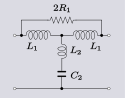
It can sometimes be useful to make such a transformation, not for the purposes of actually building the transformed circuit, but rather, for the purposes of aiding understanding of how the original circuit is working. The following circuit in bridged-T topology is a modification of a mid-series m-derived filter
M-derived filter
m-derived filters or m-type filters are a type of electronic filter designed using the image method. They were invented by Otto Zobel in the early 1920s. This filter type was originally intended for use with telephone multiplexing and was an improvement on the existing constant k type filter...
T-section. The circuit is due to Hendrik Bode who claims that the addition of the bridging resistor of a suitable value will cancel the parasitic resistance of the shunt inductor. The action of this circuit is clear if it is transformed into T topology - in this form there is a negative resistance in the shunt branch which can be made to be exactly equal to the positive parasitic resistance of the inductor.
| Description | Network | Transformed network |
|---|---|---|
| Transform 3.5 Transform of a bridged-T low-pass filter Low-pass filter A low-pass filter is an electronic filter that passes low-frequency signals but attenuates signals with frequencies higher than the cutoff frequency. The actual amount of attenuation for each frequency varies from filter to filter. It is sometimes called a high-cut filter, or treble cut filter... section to a T-section. |
 |
Any symmetrical network can be transformed into any other symmetrical network by the same method, that is, by first transforming into the intermediate lattice form (omitted for clarity from the above example transform) and from the lattice form into the required target form. As with the example, this will generally result in negative elements except in special cases.
Eliminating resistors
A theorem due to Sidney DarlingtonSidney Darlington
Sidney Darlington was an electrical engineer and inventor of a transistor configuration in 1953, the Darlington pair...
states that any PR function Z(s) can be realised as a lossless two-port terminated in a positive resistor R. That is, regardless of how many resistors feature in the matrix [Z] representing the impedance network, a transform can be found that will realise the network entirely as an LC-kind network with just one resistor across the output port (which would normally represent the load). No resistors within the network are necessary in order to realise the specified response. Consequently, it is always possible to reduce 3-element-kind 2-port networks to 2-element-kind (LC) 2-port networks provided the output port is terminated in a resistance of the required value.
Eliminating ideal transformers
An elementary transformation that can be done with ideal transformers and some other impedance element is to shift the impedance to the other side of the transformer. In all the following transforms, r is the turns ratio of the transformer.| Description | Network | Transformed network |
|---|---|---|
| Transform 4.1 Series impedance through a step-down transformer. |
||
| Transform 4.2 Shunt impedance through a step-down transformer. |
||
| Transform 4.3 Shunt and series impedance network through a step-up transformer. |
These transforms do not just apply to single elements; entire networks can be passed through the transformer. In this manner, the transformer can be shifted around the network to a more convenient location. Darlington gives an equivalent transform that can eliminate an ideal transformer altogether. This technique requires that the transformer is next to (or capable of being moved next to) an "L" network of same-kind impedances. The transform in all variants results in the "L" network facing the opposite way, that is, topologically mirrored.
| Description | Network | Transformed network |
|---|---|---|
| Transform 5.1 Elimination of a step-down transformer. |
||
| Transform 5.2 Elimination of a step-up transformer. |
||
| Example 3. Example of transform 5.1. |
Example 3 shows the result is a Π-network rather than an L-network. The reason for this is that the shunt element has more capacitance than is required by the transform so some is still left over after applying the transform. If the excess were instead, in the element nearest the transformer, this could be dealt with by first shifting the excess to the other side of the transformer before carrying out the transform.