
Alternating current
Encyclopedia
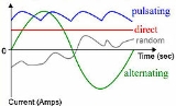
In alternating current (AC, also ac) the movement of electric charge
periodically reverses direction. In direct current
(DC, also dc), the flow of electric charge is only in one direction.
The abbreviations AC and DC are often used to mean simply alternating and direct, as when they modify current
or voltage
.
AC is the form in which electric power
is delivered to businesses and residences. The usual waveform
of an AC power
circuit is a sine wave
. In certain applications, different waveforms are used, such as triangular
or square wave
s. Audio
and radio
signals carried on electrical wires are also examples of alternating current. In these applications, an important goal is often the recovery of information encoded (or modulated) onto the AC signal.
 The earliest recorded practical application of alternating current is by Guillaume Duchenne
, inventor and developer of electrotherapy
. In 1855, he announced that AC was superior to direct current
for electrotherapeutic triggering of muscle contractions.
A power transformer
developed by Lucien Gaulard
and John Dixon Gibbs was demonstrated in London in 1881, and attracted the interest of Westinghouse
. They also exhibited the invention in Turin
in 1884, where it was adopted for an electric lighting system. Many of their designs were adapted to the particular laws governing electrical distribution in the UK.
In 1882, 1884, and 1885 Gaulard and Gibbs applied for patents on their transformer; however, these were overturned due to prior arts of Nikola Tesla
and actions initiated by Sebastian Ziani de Ferranti
.
Ferranti
went into this business in 1882 when he set up a shop in London designing various electrical devices. Ferranti believed in the success of alternating current power distribution early on, and was one of the few experts in this system in the UK. In 1887 the London Electric Supply Corporation (LESCo) hired Ferranti for the design of their power station at Deptford. He designed the building, the generating plant and the distribution system. On its completion in 1891 it was the first truly modern power station, supplying high-voltage AC power that was then "stepped down" for consumer use on each street. This basic system remains in use today around the world. Many homes all over the world still have electric meters with the Ferranti AC patent stamped on them.
William Stanley, Jr.
designed one of the first practical devices to transfer AC power efficiently between isolated circuits. Using pairs of coils wound on a common iron core, his design, called an induction coil
, was an early transformer
. The AC power system used today developed rapidly after 1886, and includes key concepts by Nikola Tesla
, who subsequently sold his patent to George Westinghouse
. Lucien Gaulard
, John Dixon Gibbs, Carl Wilhelm Siemens
and others contributed subsequently to this field. AC systems overcame the limitations of the direct current
system used by Thomas Edison
to distribute electricity efficiently over long distances even though Edison attempted to discredit alternating current as too dangerous during the War of Currents
.
The first commercial power plant in the United States using three-phase
alternating current was at the Mill Creek No. 1 Hydroelectric Plant near Redlands, California
, in 1893 designed by Almirian Decker. Decker's design incorporated 10,000-volt three-phase transmission and established the standards for the complete system of generation, transmission and motors used today.
The Ames Hydroelectric Generating Plant
(spring of 1891) and the original Niagara Falls
Adams Power Plant (August 25, 1895) were among the first AC-powered hydroelectric plants.
The Jaruga Hydroelectric Power Plant
in Croatia was set in operation on 28 August 1895. The two generators (42 Hz, 550 kW each) and the transformers were produced and installed by the Hungarian company Ganz
. The transmission line from the power plant to the City of Šibenik
was 11.5 kilometres (7.1 mi) long on wooden towers, and the municipal distribution grid 3000 V/110 V included six transforming stations.
Alternating current circuit theory developed rapidly in the latter part of the 19th and early 20th century. Notable contributors to the theoretical basis of alternating current calculations include Charles Steinmetz, James Clerk Maxwell
, Oliver Heaviside
, and many others. Calculations in unbalanced three-phase systems were simplified by the symmetrical components
methods discussed by Charles Legeyt Fortescue
in 1918.
. Use of a higher voltage
leads to significantly more efficient transmission of power. The power losses in a conductor are a product of the square of the current and the resistance
of the conductor, described by the formula
This means that when transmitting a fixed power on a given wire, if the current is doubled, the power loss will be four times greater.
The power transmitted is equal to the product of the current and the voltage (assuming no phase difference); that is,
Thus, the same amount of power can be transmitted with a lower current by increasing the voltage. It is therefore advantageous when transmitting large amounts of power to distribute the power with high voltages (often hundreds of kilovolts).
 However, high voltages also have disadvantages, the main one being the increased insulation required, and generally increased difficulty in their safe handling. In a power plant, power is generated at a convenient voltage for the design of a generator
, and then stepped up to a high voltage for transmission. Near the loads, the transmission voltage is stepped down to the voltages used by equipment. Consumer voltages vary depending on the country and size of load, but generally motors and lighting are built to use up to a few hundred volts between phases.
The utilization voltage delivered to equipment such as lighting and motor loads is standardized, with an allowable range of voltage over which equipment is expected to operate. Standard power utilization voltages and percentage tolerance vary in the different mains power systems found in the world.
Modern high-voltage, direct-current electric power transmission systems contrast with the more common alternating-current systems as a means for the efficient bulk transmission of electrical power over long distances. HVDC systems, however, tend to be more expensive and less efficient over shorter distances than transformers. Transmission with high voltage direct current was not feasible when Edison
, Westinghouse
and Tesla
were designing their power systems, since there was then no way to economically convert AC power to DC and back again at the necessary voltages.
Three-phase
electrical generation is very common. The simplest case is three separate coils in the generator stator
that are physically offset by an angle of 120° to each other. Three current waveforms are produced that are equal in magnitude and 120° out of phase to each other. If coils are added opposite to these (60° spacing), they generate the same phases with reverse polarity and so can be simply wired together.
In practice, higher "pole orders" are commonly used. For example, a 12-pole machine would have 36 coils (10° spacing). The advantage is that lower speeds can be used. For example, a 2-pole machine running at 3600 rpm and a 12-pole machine running at 600 rpm produce the same frequency. This is much more practical for larger machines.
If the load on a three-phase system is balanced equally among the phases, no current flows through the neutral point. Even in the worst-case unbalanced (linear) load, the neutral current will not exceed the highest of the phase currents. Non-linear loads (e.g. computers) may require an oversized neutral bus and neutral conductor in the upstream distribution panel to handle harmonics. Harmonics can cause neutral conductor current levels to exceed that of one or all phase conductors.
For three-phase at utilization voltages a four-wire system is often used. When stepping down three-phase, a transformer with a Delta (3-wire) primary and a Star (4-wire, center-earthed) secondary is often used so there is no need for a neutral on the supply side.
For smaller customers (just how small varies by country and age of the installation) only a single phase and the neutral or two phases and the neutral are taken to the property. For larger installations all three phases and the neutral are taken to the main distribution panel. From the three-phase main panel, both single and three-phase circuits may lead off.
Three-wire single-phase systems, with a single center-tapped transformer giving two live conductors, is a common distribution scheme for residential and small commercial buildings in North America. This arrangement is sometimes incorrectly referred to as "two phase". A similar method is used for a different reason on construction sites in the UK. Small power tools and lighting are supposed to be supplied by a local center-tapped transformer with a voltage of 55 V between each power conductor and earth. This significantly reduces the risk of electric shock
in the event that one of the live conductors becomes exposed through an equipment fault whilst still allowing a reasonable voltage of 110 V between the two conductors for running the tools.
A third wire
, called the bond (or earth) wire, is often connected between non-current-carrying metal enclosures and earth ground. This conductor provides protection from electric shock due to accidental contact of circuit conductors with the metal chassis of portable appliances and tools. Bonding all non-current-carrying metal parts into one complete system ensures there is always a low electrical impedance
path to ground sufficient to carry any fault
current for as long as it takes for the system to clear the fault. This low impedance path allows the maximum amount of fault current, causing the overcurrent protection device (breakers, fuses) to trip or burn out as quickly as possible, bringing the electrical system to a safe state. All bond wires are bonded to ground at the main service panel, as is the Neutral/Identified conductor if present.
varies by country; most electric power is generated at either 50 or 60 Hertz
. Some countries have a mixture of 50 Hz and 60 Hz supplies, notably Japan.
A low frequency eases the design of low-speed electric motors, particularly for hoisting, crushing and rolling applications, and commutator-type traction motor
s for applications such as railways, but also causes a noticeable flicker in incandescent lighting and an objectionable flicker in fluorescent lamp
s. 16.7 Hz power (in former times nominal 16 2/3 cycles per second, practically invariably) is still used in some European rail systems, such as in Austria
, Germany
, Norway
, Sweden
and Switzerland
. The use of lower frequencies also provided the advantage of lower impedance losses, which are proportional to frequency. The original Niagara Falls generators were built to produce 25 Hz power, as a compromise between low frequency for traction and heavy induction motors, while still allowing incandescent lighting to operate (although with noticeable flicker); most of the 25 Hz residential and commercial customers for Niagara Falls power were converted to 60 Hz by the late 1950s, although some 25 Hz industrial customers still existed as of the start of the 21st century.
Off-shore, military, textile industry, marine, computer mainframe
, aircraft, and spacecraft applications sometimes use 400 Hz, for benefits of reduced weight of apparatus or higher motor speeds.
in an alternating current produces waves of electromagnetic radiation
that cancel the propagation of electricity toward the center of materials with high conductivity. This phenomenon is called skin effect
.
At very high frequencies the current no longer flows in the wire, but effectively flows on the surface of the wire, within a thickness of a few skin depths. The skin depth is the thickness at which the current density is reduced by 63%. Even at relatively low frequencies used for high power transmission (50–60 Hz), non-uniform distribution of current still occurs in sufficiently thick conductors. For example, the skin depth of a copper conductor is approximately 8.57 mm at 60 Hz, so high current conductors are usually hollow to reduce their mass and cost.
Since the current tends to flow in the periphery of conductors, the effective cross-section of the conductor is reduced. This increases the effective AC resistance
of the conductor, since resistance is inversely proportional to the cross-sectional area in which the current actually flows. The AC resistance often is many times higher than the DC resistance, causing a much higher energy loss due to ohmic heating (also called I2R loss).
. This measure helps to partially mitigate skin effect by forcing more equal current throughout the total cross section of the stranded conductors. Litz wire is used for making high-Q inductor
s, reducing losses in flexible conductors carrying very high currents at lower frequencies, and in the windings of devices carrying higher radio frequency
current (up to hundreds of kilohertz), such as switch-mode power supplies
and radio frequency
transformer
s.
under periodic acceleration
, which causes radiation
of electromagnetic waves. Energy that is radiated is lost. Depending on the frequency, different techniques are used to minimize the loss due to radiation.
. This reduces losses from electromagnetic radiation
and inductive coupling
. A twisted pair must be used with a balanced signalling system, so that the two wires carry equal but opposite currents. Each wire in a twisted pair radiates a signal, but it is effectively cancelled by radiation from the other wire, resulting in almost no radiation loss.
s are commonly used at audio frequencies and above for convenience. A coaxial cable has a conductive wire inside a conductive tube, separated by a dielectric
layer. The current flowing on the inner conductor is equal and opposite to the current flowing on the inner surface of the tube. The electromagnetic field is thus completely contained within the tube, and (ideally) no energy is lost to radiation or coupling outside the tube. Coaxial cables have acceptably small losses for frequencies up to about 5 GHz. For microwave
frequencies greater than 5 GHz, the losses (due mainly to the electrical resistance of the central conductor) become too large, making waveguides
a more efficient medium for transmitting energy. Coaxial cables with an air rather than solid dielectric are preferred as they transmit power with lower losses.
are similar to coax cables, as both consist of tubes, with the biggest difference being that the waveguide has no inner conductor. Waveguides can have any arbitrary cross section, but rectangular cross sections are the most common. Because waveguides do not have an inner conductor to carry a return current, waveguides cannot deliver energy by means of an electric current
, but rather by means of a guided electromagnetic field
. Although surface currents
do flow on the inner walls of the waveguides, those surface currents do not carry power. Power is carried by the guided electromagnetic fields. The surface currents are set up by the guided electromagnetic fields and have the effect of keeping the fields inside the waveguide and preventing leakage of the fields to the space outside the waveguide.
Waveguides have dimensions comparable to the wavelength
of the alternating current to be transmitted, so they are only feasible at microwave frequencies. In addition to this mechanical feasibility, electrical resistance
of the non-ideal metals forming the walls of the waveguide cause dissipation
of power (surface currents flowing on lossy conductors
dissipate power). At higher frequencies, the power lost to this dissipation becomes unacceptably large.
of time by the following equation:
 ,
,
where
The peak-to-peak value of an AC voltage is defined as the difference between its positive peak and its negative peak. Since the maximum value of is +1 and the minimum value is −1, an AC voltage swings between
  and
and  . The peak-to-peak voltage, usually written as
  or
or  , is therefore
  .
.
 where
where  represents a load resistance.
Rather than using instantaneous power, , it is more practical to use a time averaged power (where the averaging is performed over any integer number of cycles). Therefore, AC voltage is often expressed as a root mean square
(RMS) value, written as , because
For a sinusoidal voltage:
The factor is called the crest factor
, which varies for different waveforms.
value is 230 V. This means that the time-averaged power delivered is equivalent to the power delivered by a DC voltage of 230 V. To determine the peak voltage (amplitude), we can rearrange the above equation to:
For our 230 V AC, the peak voltage is therefore
  , which is about 325 V. The peak-to-peak value
  of the 230 V AC is double that, at about 650 V.
Note that some countries use a frequency of 50 Hz, while others use a frequency of 60 Hz. The calculation to convert from RMS voltage to peak voltage is independent of the frequency.
Electric charge
Electric charge is a physical property of matter that causes it to experience a force when near other electrically charged matter. Electric charge comes in two types, called positive and negative. Two positively charged substances, or objects, experience a mutual repulsive force, as do two...
periodically reverses direction. In direct current
Direct current
Direct current is the unidirectional flow of electric charge. Direct current is produced by such sources as batteries, thermocouples, solar cells, and commutator-type electric machines of the dynamo type. Direct current may flow in a conductor such as a wire, but can also flow through...
(DC, also dc), the flow of electric charge is only in one direction.
The abbreviations AC and DC are often used to mean simply alternating and direct, as when they modify current
Electric current
Electric current is a flow of electric charge through a medium.This charge is typically carried by moving electrons in a conductor such as wire...
or voltage
Voltage
Voltage, otherwise known as electrical potential difference or electric tension is the difference in electric potential between two points — or the difference in electric potential energy per unit charge between two points...
.
AC is the form in which electric power
Electric power
Electric power is the rate at which electric energy is transferred by an electric circuit. The SI unit of power is the watt.-Circuits:Electric power, like mechanical power, is represented by the letter P in electrical equations...
is delivered to businesses and residences. The usual waveform
Waveform
Waveform means the shape and form of a signal such as a wave moving in a physical medium or an abstract representation.In many cases the medium in which the wave is being propagated does not permit a direct visual image of the form. In these cases, the term 'waveform' refers to the shape of a graph...
of an AC power
AC power
Power in an electric circuit is the rate of flow of energy past a given point of the circuit. In alternating current circuits, energy storage elements such as inductance and capacitance may result in periodic reversals of the direction of energy flow...
circuit is a sine wave
Sine wave
The sine wave or sinusoid is a mathematical function that describes a smooth repetitive oscillation. It occurs often in pure mathematics, as well as physics, signal processing, electrical engineering and many other fields...
. In certain applications, different waveforms are used, such as triangular
Triangle wave
A triangle wave is a non-sinusoidal waveform named for its triangular shape.Like a square wave, the triangle wave contains only odd harmonics...
or square wave
Square wave
A square wave is a kind of non-sinusoidal waveform, most typically encountered in electronics and signal processing. An ideal square wave alternates regularly and instantaneously between two levels...
s. Audio
Audio frequency
An audio frequency or audible frequency is characterized as a periodic vibration whose frequency is audible to the average human...
and radio
Radio frequency
Radio frequency is a rate of oscillation in the range of about 3 kHz to 300 GHz, which corresponds to the frequency of radio waves, and the alternating currents which carry radio signals...
signals carried on electrical wires are also examples of alternating current. In these applications, an important goal is often the recovery of information encoded (or modulated) onto the AC signal.
History
Guillaume Duchenne
Guillaume-Benjamin-Amand Duchenne was a French neurologist who revived Galvani's research and greatly advanced the science of electrophysiology...
, inventor and developer of electrotherapy
Electrotherapy
Electrotherapy is the use of electrical energy as a medical treatment In medicine, the term electrotherapy can apply to a variety of treatments, including the use of electrical devices such as deep brain stimulators for neurological disease. The term has also been applied specifically to the use of...
. In 1855, he announced that AC was superior to direct current
Direct current
Direct current is the unidirectional flow of electric charge. Direct current is produced by such sources as batteries, thermocouples, solar cells, and commutator-type electric machines of the dynamo type. Direct current may flow in a conductor such as a wire, but can also flow through...
for electrotherapeutic triggering of muscle contractions.
A power transformer
Transformer
A transformer is a device that transfers electrical energy from one circuit to another through inductively coupled conductors—the transformer's coils. A varying current in the first or primary winding creates a varying magnetic flux in the transformer's core and thus a varying magnetic field...
developed by Lucien Gaulard
Lucien Gaulard
Lucien Gaulard invented devices for the transmission of alternating current electrical energy.-Biography:Gaulard was born in Paris, France....
and John Dixon Gibbs was demonstrated in London in 1881, and attracted the interest of Westinghouse
Westinghouse Electric (1886)
Westinghouse Electric was an American manufacturing company. It was founded in 1886 as Westinghouse Electric Company and later renamed Westinghouse Electric Corporation by George Westinghouse. The company purchased CBS in 1995 and became CBS Corporation in 1997...
. They also exhibited the invention in Turin
Turin
Turin is a city and major business and cultural centre in northern Italy, capital of the Piedmont region, located mainly on the left bank of the Po River and surrounded by the Alpine arch. The population of the city proper is 909,193 while the population of the urban area is estimated by Eurostat...
in 1884, where it was adopted for an electric lighting system. Many of their designs were adapted to the particular laws governing electrical distribution in the UK.
In 1882, 1884, and 1885 Gaulard and Gibbs applied for patents on their transformer; however, these were overturned due to prior arts of Nikola Tesla
Nikola Tesla
Nikola Tesla was a Serbian-American inventor, mechanical engineer, and electrical engineer...
and actions initiated by Sebastian Ziani de Ferranti
Sebastian Ziani de Ferranti
Sebastian Pietro Innocenzo Adhemar Ziani de Ferranti was an electrical engineer and inventor.-Personal life:...
.
Ferranti
Ferranti
Ferranti or Ferranti International plc was a UK electrical engineering and equipment firm that operated for over a century from 1885 until it went bankrupt in 1993. Known primarily for defence electronics, the Company was once a constituent of the FTSE 100 Index but ceased trading in 1993.The...
went into this business in 1882 when he set up a shop in London designing various electrical devices. Ferranti believed in the success of alternating current power distribution early on, and was one of the few experts in this system in the UK. In 1887 the London Electric Supply Corporation (LESCo) hired Ferranti for the design of their power station at Deptford. He designed the building, the generating plant and the distribution system. On its completion in 1891 it was the first truly modern power station, supplying high-voltage AC power that was then "stepped down" for consumer use on each street. This basic system remains in use today around the world. Many homes all over the world still have electric meters with the Ferranti AC patent stamped on them.
William Stanley, Jr.
William Stanley, Jr.
William Stanley, Jr. was an American physicist born in Brooklyn, New York. In his career, he obtained 129 patents covering a variety of electric devices.-Biography:...
designed one of the first practical devices to transfer AC power efficiently between isolated circuits. Using pairs of coils wound on a common iron core, his design, called an induction coil
Induction coil
An induction coil or "spark coil" is a type of disruptive discharge coil. It is a type of electrical transformer used to produce high-voltage pulses from a low-voltage direct current supply...
, was an early transformer
Transformer
A transformer is a device that transfers electrical energy from one circuit to another through inductively coupled conductors—the transformer's coils. A varying current in the first or primary winding creates a varying magnetic flux in the transformer's core and thus a varying magnetic field...
. The AC power system used today developed rapidly after 1886, and includes key concepts by Nikola Tesla
Nikola Tesla
Nikola Tesla was a Serbian-American inventor, mechanical engineer, and electrical engineer...
, who subsequently sold his patent to George Westinghouse
George Westinghouse
George Westinghouse, Jr was an American entrepreneur and engineer who invented the railway air brake and was a pioneer of the electrical industry. Westinghouse was one of Thomas Edison's main rivals in the early implementation of the American electricity system...
. Lucien Gaulard
Lucien Gaulard
Lucien Gaulard invented devices for the transmission of alternating current electrical energy.-Biography:Gaulard was born in Paris, France....
, John Dixon Gibbs, Carl Wilhelm Siemens
Carl Wilhelm Siemens
Carl Wilhelm Siemens was a German born engineer who for most of his life worked in Britain and later became a British subject.-Biography:...
and others contributed subsequently to this field. AC systems overcame the limitations of the direct current
Direct current
Direct current is the unidirectional flow of electric charge. Direct current is produced by such sources as batteries, thermocouples, solar cells, and commutator-type electric machines of the dynamo type. Direct current may flow in a conductor such as a wire, but can also flow through...
system used by Thomas Edison
Thomas Edison
Thomas Alva Edison was an American inventor and businessman. He developed many devices that greatly influenced life around the world, including the phonograph, the motion picture camera, and a long-lasting, practical electric light bulb. In addition, he created the world’s first industrial...
to distribute electricity efficiently over long distances even though Edison attempted to discredit alternating current as too dangerous during the War of Currents
War of Currents
In the "War of Currents" era in the late 1880s, George Westinghouse and Thomas Edison became adversaries due to Edison's promotion of direct current for electric power distribution over alternating current advocated by several European companies and Westinghouse Electric based out of Pittsburgh,...
.
The first commercial power plant in the United States using three-phase
Three-phase
In electrical engineering, three-phase electric power systems have at least three conductors carrying voltage waveforms that are radians offset in time...
alternating current was at the Mill Creek No. 1 Hydroelectric Plant near Redlands, California
Redlands, California
Redlands is a city in San Bernardino County, California, United States. As of the 2010 census, the city had a population of 68,747, up from 63,591 at the 2000 census. The city is located east of downtown San Bernardino.- History :...
, in 1893 designed by Almirian Decker. Decker's design incorporated 10,000-volt three-phase transmission and established the standards for the complete system of generation, transmission and motors used today.
The Ames Hydroelectric Generating Plant
Ames Hydroelectric Generating Plant
The Ames Hydroelectric Generating Plant, located near Ophir, Colorado, was the world's first commercial system to produce and transmit alternating current electricity. It is now on the List of IEEE Milestones....
(spring of 1891) and the original Niagara Falls
Niagara Falls
The Niagara Falls, located on the Niagara River draining Lake Erie into Lake Ontario, is the collective name for the Horseshoe Falls and the adjacent American Falls along with the comparatively small Bridal Veil Falls, which combined form the highest flow rate of any waterfalls in the world and has...
Adams Power Plant (August 25, 1895) were among the first AC-powered hydroelectric plants.
The Jaruga Hydroelectric Power Plant
Jaruga Hydroelectric Power Plant
Jaruga Hydroelectric Power Plant is a hydroelectric power plant on river Krka, located in Šibenik-Knin county, in central Dalmatia, Croatia.The Jaruga is one of the oldest power-generating facilities in the world...
in Croatia was set in operation on 28 August 1895. The two generators (42 Hz, 550 kW each) and the transformers were produced and installed by the Hungarian company Ganz
Ganz
The Ganz electric works in Budapest is probably best known for the manufacture of tramcars, but was also a pioneer in the application of three-phase alternating current to electric railways. Ganz also made / makes: ships , bridge steel structures , high voltage equipment...
. The transmission line from the power plant to the City of Šibenik
Šibenik
Šibenik is a historic town in Croatia, with population of 51,553 . It is located in central Dalmatia where the river Krka flows into the Adriatic Sea...
was 11.5 kilometres (7.1 mi) long on wooden towers, and the municipal distribution grid 3000 V/110 V included six transforming stations.
Alternating current circuit theory developed rapidly in the latter part of the 19th and early 20th century. Notable contributors to the theoretical basis of alternating current calculations include Charles Steinmetz, James Clerk Maxwell
James Clerk Maxwell
James Clerk Maxwell of Glenlair was a Scottish physicist and mathematician. His most prominent achievement was formulating classical electromagnetic theory. This united all previously unrelated observations, experiments and equations of electricity, magnetism and optics into a consistent theory...
, Oliver Heaviside
Oliver Heaviside
Oliver Heaviside was a self-taught English electrical engineer, mathematician, and physicist who adapted complex numbers to the study of electrical circuits, invented mathematical techniques to the solution of differential equations , reformulated Maxwell's field equations in terms of electric and...
, and many others. Calculations in unbalanced three-phase systems were simplified by the symmetrical components
Symmetrical components
In electrical engineering, the method of symmetrical components is used to simplify analysis of unbalanced three phase power systems under both normal and abnormal conditions.-Description:...
methods discussed by Charles Legeyt Fortescue
Charles Legeyt Fortescue
Charles LeGeyt Fortescue was an electrical engineer. He was born in York Factory, in what is now Manitoba where the Hayes River enters Hudson Bay...
in 1918.
Transmission, distribution, and domestic power supply
AC voltage may be increased or decreased with a transformerTransformer
A transformer is a device that transfers electrical energy from one circuit to another through inductively coupled conductors—the transformer's coils. A varying current in the first or primary winding creates a varying magnetic flux in the transformer's core and thus a varying magnetic field...
. Use of a higher voltage
Voltage
Voltage, otherwise known as electrical potential difference or electric tension is the difference in electric potential between two points — or the difference in electric potential energy per unit charge between two points...
leads to significantly more efficient transmission of power. The power losses in a conductor are a product of the square of the current and the resistance
Electrical resistance
The electrical resistance of an electrical element is the opposition to the passage of an electric current through that element; the inverse quantity is electrical conductance, the ease at which an electric current passes. Electrical resistance shares some conceptual parallels with the mechanical...
of the conductor, described by the formula
This means that when transmitting a fixed power on a given wire, if the current is doubled, the power loss will be four times greater.
The power transmitted is equal to the product of the current and the voltage (assuming no phase difference); that is,
Thus, the same amount of power can be transmitted with a lower current by increasing the voltage. It is therefore advantageous when transmitting large amounts of power to distribute the power with high voltages (often hundreds of kilovolts).
Electrical generator
In electricity generation, an electric generator is a device that converts mechanical energy to electrical energy. A generator forces electric charge to flow through an external electrical circuit. It is analogous to a water pump, which causes water to flow...
, and then stepped up to a high voltage for transmission. Near the loads, the transmission voltage is stepped down to the voltages used by equipment. Consumer voltages vary depending on the country and size of load, but generally motors and lighting are built to use up to a few hundred volts between phases.
The utilization voltage delivered to equipment such as lighting and motor loads is standardized, with an allowable range of voltage over which equipment is expected to operate. Standard power utilization voltages and percentage tolerance vary in the different mains power systems found in the world.
Modern high-voltage, direct-current electric power transmission systems contrast with the more common alternating-current systems as a means for the efficient bulk transmission of electrical power over long distances. HVDC systems, however, tend to be more expensive and less efficient over shorter distances than transformers. Transmission with high voltage direct current was not feasible when Edison
Thomas Edison
Thomas Alva Edison was an American inventor and businessman. He developed many devices that greatly influenced life around the world, including the phonograph, the motion picture camera, and a long-lasting, practical electric light bulb. In addition, he created the world’s first industrial...
, Westinghouse
George Westinghouse
George Westinghouse, Jr was an American entrepreneur and engineer who invented the railway air brake and was a pioneer of the electrical industry. Westinghouse was one of Thomas Edison's main rivals in the early implementation of the American electricity system...
and Tesla
Nikola Tesla
Nikola Tesla was a Serbian-American inventor, mechanical engineer, and electrical engineer...
were designing their power systems, since there was then no way to economically convert AC power to DC and back again at the necessary voltages.
Three-phase
Three-phase electric power
Three-phase electric power is a common method of alternating-current electric power generation, transmission, and distribution. It is a type of polyphase system and is the most common method used by grids worldwide to transfer power. It is also used to power large motors and other heavy loads...
electrical generation is very common. The simplest case is three separate coils in the generator stator
Stator
The stator is the stationary part of a rotor system, found in an electric generator, electric motor and biological rotors.Depending on the configuration of a spinning electromotive device the stator may act as the field magnet, interacting with the armature to create motion, or it may act as the...
that are physically offset by an angle of 120° to each other. Three current waveforms are produced that are equal in magnitude and 120° out of phase to each other. If coils are added opposite to these (60° spacing), they generate the same phases with reverse polarity and so can be simply wired together.
In practice, higher "pole orders" are commonly used. For example, a 12-pole machine would have 36 coils (10° spacing). The advantage is that lower speeds can be used. For example, a 2-pole machine running at 3600 rpm and a 12-pole machine running at 600 rpm produce the same frequency. This is much more practical for larger machines.
If the load on a three-phase system is balanced equally among the phases, no current flows through the neutral point. Even in the worst-case unbalanced (linear) load, the neutral current will not exceed the highest of the phase currents. Non-linear loads (e.g. computers) may require an oversized neutral bus and neutral conductor in the upstream distribution panel to handle harmonics. Harmonics can cause neutral conductor current levels to exceed that of one or all phase conductors.
For three-phase at utilization voltages a four-wire system is often used. When stepping down three-phase, a transformer with a Delta (3-wire) primary and a Star (4-wire, center-earthed) secondary is often used so there is no need for a neutral on the supply side.
For smaller customers (just how small varies by country and age of the installation) only a single phase and the neutral or two phases and the neutral are taken to the property. For larger installations all three phases and the neutral are taken to the main distribution panel. From the three-phase main panel, both single and three-phase circuits may lead off.
Three-wire single-phase systems, with a single center-tapped transformer giving two live conductors, is a common distribution scheme for residential and small commercial buildings in North America. This arrangement is sometimes incorrectly referred to as "two phase". A similar method is used for a different reason on construction sites in the UK. Small power tools and lighting are supposed to be supplied by a local center-tapped transformer with a voltage of 55 V between each power conductor and earth. This significantly reduces the risk of electric shock
Electric shock
Electric Shock of a body with any source of electricity that causes a sufficient current through the skin, muscles or hair. Typically, the expression is used to denote an unwanted exposure to electricity, hence the effects are considered undesirable....
in the event that one of the live conductors becomes exposed through an equipment fault whilst still allowing a reasonable voltage of 110 V between the two conductors for running the tools.
A third wire
Ground and neutral
Since the neutral point of an electrical supply system is often connected to earth ground, ground and neutral are closely related. Under certain conditions, a conductor used to connect to a system neutral is also used for grounding of equipment and structures...
, called the bond (or earth) wire, is often connected between non-current-carrying metal enclosures and earth ground. This conductor provides protection from electric shock due to accidental contact of circuit conductors with the metal chassis of portable appliances and tools. Bonding all non-current-carrying metal parts into one complete system ensures there is always a low electrical impedance
Electrical impedance
Electrical impedance, or simply impedance, is the measure of the opposition that an electrical circuit presents to the passage of a current when a voltage is applied. In quantitative terms, it is the complex ratio of the voltage to the current in an alternating current circuit...
path to ground sufficient to carry any fault
Fault (power engineering)
In an electric power system, a fault is any abnormal flow of electric current. For example, a short circuit is a fault in which current flow bypasses the normal load. An open-circuit fault occurs if a circuit is interrupted by some failure. In three-phase systems, a fault may involve one or more...
current for as long as it takes for the system to clear the fault. This low impedance path allows the maximum amount of fault current, causing the overcurrent protection device (breakers, fuses) to trip or burn out as quickly as possible, bringing the electrical system to a safe state. All bond wires are bonded to ground at the main service panel, as is the Neutral/Identified conductor if present.
AC power supply frequencies
The frequency of the electrical systemUtility frequency
The utility frequency, line frequency or mains frequency is the frequency at which alternating current is transmitted from a power plant to the end-user. In most parts of the world this is 50 Hz, although in the Americas it is typically 60 Hz...
varies by country; most electric power is generated at either 50 or 60 Hertz
Hertz
The hertz is the SI unit of frequency defined as the number of cycles per second of a periodic phenomenon. One of its most common uses is the description of the sine wave, particularly those used in radio and audio applications....
. Some countries have a mixture of 50 Hz and 60 Hz supplies, notably Japan.
A low frequency eases the design of low-speed electric motors, particularly for hoisting, crushing and rolling applications, and commutator-type traction motor
Traction motor
Traction motor refers to an electric motor providing the primary rotational torque of a machine, usually for conversion into linear motion ....
s for applications such as railways, but also causes a noticeable flicker in incandescent lighting and an objectionable flicker in fluorescent lamp
Fluorescent lamp
A fluorescent lamp or fluorescent tube is a gas-discharge lamp that uses electricity to excite mercury vapor. The excited mercury atoms produce short-wave ultraviolet light that then causes a phosphor to fluoresce, producing visible light. A fluorescent lamp converts electrical power into useful...
s. 16.7 Hz power (in former times nominal 16 2/3 cycles per second, practically invariably) is still used in some European rail systems, such as in Austria
Austria
Austria , officially the Republic of Austria , is a landlocked country of roughly 8.4 million people in Central Europe. It is bordered by the Czech Republic and Germany to the north, Slovakia and Hungary to the east, Slovenia and Italy to the south, and Switzerland and Liechtenstein to the...
, Germany
Germany
Germany , officially the Federal Republic of Germany , is a federal parliamentary republic in Europe. The country consists of 16 states while the capital and largest city is Berlin. Germany covers an area of 357,021 km2 and has a largely temperate seasonal climate...
, Norway
Norway
Norway , officially the Kingdom of Norway, is a Nordic unitary constitutional monarchy whose territory comprises the western portion of the Scandinavian Peninsula, Jan Mayen, and the Arctic archipelago of Svalbard and Bouvet Island. Norway has a total area of and a population of about 4.9 million...
, Sweden
Sweden
Sweden , officially the Kingdom of Sweden , is a Nordic country on the Scandinavian Peninsula in Northern Europe. Sweden borders with Norway and Finland and is connected to Denmark by a bridge-tunnel across the Öresund....
and Switzerland
Switzerland
Switzerland name of one of the Swiss cantons. ; ; ; or ), in its full name the Swiss Confederation , is a federal republic consisting of 26 cantons, with Bern as the seat of the federal authorities. The country is situated in Western Europe,Or Central Europe depending on the definition....
. The use of lower frequencies also provided the advantage of lower impedance losses, which are proportional to frequency. The original Niagara Falls generators were built to produce 25 Hz power, as a compromise between low frequency for traction and heavy induction motors, while still allowing incandescent lighting to operate (although with noticeable flicker); most of the 25 Hz residential and commercial customers for Niagara Falls power were converted to 60 Hz by the late 1950s, although some 25 Hz industrial customers still existed as of the start of the 21st century.
Off-shore, military, textile industry, marine, computer mainframe
Mainframe computer
Mainframes are powerful computers used primarily by corporate and governmental organizations for critical applications, bulk data processing such as census, industry and consumer statistics, enterprise resource planning, and financial transaction processing.The term originally referred to the...
, aircraft, and spacecraft applications sometimes use 400 Hz, for benefits of reduced weight of apparatus or higher motor speeds.
Effects at high frequencies
A direct current flows constantly and uniformly throughout the cross-section of a uniform wire. An alternating current of any frequency is forced away from the wire's center, toward its outer surface. This is because the acceleration of an electric chargeElectric charge
Electric charge is a physical property of matter that causes it to experience a force when near other electrically charged matter. Electric charge comes in two types, called positive and negative. Two positively charged substances, or objects, experience a mutual repulsive force, as do two...
in an alternating current produces waves of electromagnetic radiation
Electromagnetic radiation
Electromagnetic radiation is a form of energy that exhibits wave-like behavior as it travels through space...
that cancel the propagation of electricity toward the center of materials with high conductivity. This phenomenon is called skin effect
Skin effect
Skin effect is the tendency of an alternating electric current to distribute itself within a conductor with the current density being largest near the surface of the conductor, decreasing at greater depths. In other words, the electric current flows mainly at the "skin" of the conductor, at an...
.
At very high frequencies the current no longer flows in the wire, but effectively flows on the surface of the wire, within a thickness of a few skin depths. The skin depth is the thickness at which the current density is reduced by 63%. Even at relatively low frequencies used for high power transmission (50–60 Hz), non-uniform distribution of current still occurs in sufficiently thick conductors. For example, the skin depth of a copper conductor is approximately 8.57 mm at 60 Hz, so high current conductors are usually hollow to reduce their mass and cost.
Since the current tends to flow in the periphery of conductors, the effective cross-section of the conductor is reduced. This increases the effective AC resistance
Electrical resistance
The electrical resistance of an electrical element is the opposition to the passage of an electric current through that element; the inverse quantity is electrical conductance, the ease at which an electric current passes. Electrical resistance shares some conceptual parallels with the mechanical...
of the conductor, since resistance is inversely proportional to the cross-sectional area in which the current actually flows. The AC resistance often is many times higher than the DC resistance, causing a much higher energy loss due to ohmic heating (also called I2R loss).
Techniques for reducing AC resistance
For low to medium frequencies, conductors can be divided into stranded wires, each insulated from one other, and the relative positions of individual strands specially arranged within the conductor bundle. Wire constructed using this technique is called Litz wireLitz wire
Litz wire is a type of cable used in electronics to carry alternating current. The wire is designed to reduce the skin effect and proximity effect losses in conductors used at frequencies up to about 1 MHz...
. This measure helps to partially mitigate skin effect by forcing more equal current throughout the total cross section of the stranded conductors. Litz wire is used for making high-Q inductor
Inductor
An inductor is a passive two-terminal electrical component used to store energy in a magnetic field. An inductor's ability to store magnetic energy is measured by its inductance, in units of henries...
s, reducing losses in flexible conductors carrying very high currents at lower frequencies, and in the windings of devices carrying higher radio frequency
Radio frequency
Radio frequency is a rate of oscillation in the range of about 3 kHz to 300 GHz, which corresponds to the frequency of radio waves, and the alternating currents which carry radio signals...
current (up to hundreds of kilohertz), such as switch-mode power supplies
Power supply
A power supply is a device that supplies electrical energy to one or more electric loads. The term is most commonly applied to devices that convert one form of electrical energy to another, though it may also refer to devices that convert another form of energy to electrical energy...
and radio frequency
Radio frequency
Radio frequency is a rate of oscillation in the range of about 3 kHz to 300 GHz, which corresponds to the frequency of radio waves, and the alternating currents which carry radio signals...
transformer
Transformer
A transformer is a device that transfers electrical energy from one circuit to another through inductively coupled conductors—the transformer's coils. A varying current in the first or primary winding creates a varying magnetic flux in the transformer's core and thus a varying magnetic field...
s.
Techniques for reducing radiation loss
As written above, an alternating current is made of electric chargeElectric charge
Electric charge is a physical property of matter that causes it to experience a force when near other electrically charged matter. Electric charge comes in two types, called positive and negative. Two positively charged substances, or objects, experience a mutual repulsive force, as do two...
under periodic acceleration
Acceleration
In physics, acceleration is the rate of change of velocity with time. In one dimension, acceleration is the rate at which something speeds up or slows down. However, since velocity is a vector, acceleration describes the rate of change of both the magnitude and the direction of velocity. ...
, which causes radiation
Electromagnetic radiation
Electromagnetic radiation is a form of energy that exhibits wave-like behavior as it travels through space...
of electromagnetic waves. Energy that is radiated is lost. Depending on the frequency, different techniques are used to minimize the loss due to radiation.
Twisted pairs
At frequencies up to about 1 GHz, pairs of wires are twisted together in a cable, forming a twisted pairTwisted pair
Twisted pair cabling is a type of wiring in which two conductors are twisted together for the purposes of canceling out electromagnetic interference from external sources; for instance, electromagnetic radiation from unshielded twisted pair cables, and crosstalk between neighboring pairs...
. This reduces losses from electromagnetic radiation
Electromagnetic radiation
Electromagnetic radiation is a form of energy that exhibits wave-like behavior as it travels through space...
and inductive coupling
Inductive coupling
In electrical engineering, two conductors are referred to as mutual-inductively coupled or magnetically coupled when they are configured such that change in current flow through one wire induces a voltage across the ends of the other wire through electromagnetic induction...
. A twisted pair must be used with a balanced signalling system, so that the two wires carry equal but opposite currents. Each wire in a twisted pair radiates a signal, but it is effectively cancelled by radiation from the other wire, resulting in almost no radiation loss.
Coaxial cables
Coaxial cableCoaxial cable
Coaxial cable, or coax, has an inner conductor surrounded by a flexible, tubular insulating layer, surrounded by a tubular conducting shield. The term coaxial comes from the inner conductor and the outer shield sharing the same geometric axis...
s are commonly used at audio frequencies and above for convenience. A coaxial cable has a conductive wire inside a conductive tube, separated by a dielectric
Dielectric
A dielectric is an electrical insulator that can be polarized by an applied electric field. When a dielectric is placed in an electric field, electric charges do not flow through the material, as in a conductor, but only slightly shift from their average equilibrium positions causing dielectric...
layer. The current flowing on the inner conductor is equal and opposite to the current flowing on the inner surface of the tube. The electromagnetic field is thus completely contained within the tube, and (ideally) no energy is lost to radiation or coupling outside the tube. Coaxial cables have acceptably small losses for frequencies up to about 5 GHz. For microwave
Microwave
Microwaves, a subset of radio waves, have wavelengths ranging from as long as one meter to as short as one millimeter, or equivalently, with frequencies between 300 MHz and 300 GHz. This broad definition includes both UHF and EHF , and various sources use different boundaries...
frequencies greater than 5 GHz, the losses (due mainly to the electrical resistance of the central conductor) become too large, making waveguides
Waveguide (electromagnetism)
In electromagnetics and communications engineering, the term waveguide may refer to any linear structure that conveys electromagnetic waves between its endpoints. However, the original and most common meaning is a hollow metal pipe used to carry radio waves...
a more efficient medium for transmitting energy. Coaxial cables with an air rather than solid dielectric are preferred as they transmit power with lower losses.
Waveguides
WaveguidesWaveguide (electromagnetism)
In electromagnetics and communications engineering, the term waveguide may refer to any linear structure that conveys electromagnetic waves between its endpoints. However, the original and most common meaning is a hollow metal pipe used to carry radio waves...
are similar to coax cables, as both consist of tubes, with the biggest difference being that the waveguide has no inner conductor. Waveguides can have any arbitrary cross section, but rectangular cross sections are the most common. Because waveguides do not have an inner conductor to carry a return current, waveguides cannot deliver energy by means of an electric current
Electric current
Electric current is a flow of electric charge through a medium.This charge is typically carried by moving electrons in a conductor such as wire...
, but rather by means of a guided electromagnetic field
Electromagnetic field
An electromagnetic field is a physical field produced by moving electrically charged objects. It affects the behavior of charged objects in the vicinity of the field. The electromagnetic field extends indefinitely throughout space and describes the electromagnetic interaction...
. Although surface currents
Current density
Current density is a measure of the density of flow of a conserved charge. Usually the charge is the electric charge, in which case the associated current density is the electric current per unit area of cross section, but the term current density can also be applied to other conserved...
do flow on the inner walls of the waveguides, those surface currents do not carry power. Power is carried by the guided electromagnetic fields. The surface currents are set up by the guided electromagnetic fields and have the effect of keeping the fields inside the waveguide and preventing leakage of the fields to the space outside the waveguide.
Waveguides have dimensions comparable to the wavelength
Wavelength
In physics, the wavelength of a sinusoidal wave is the spatial period of the wave—the distance over which the wave's shape repeats.It is usually determined by considering the distance between consecutive corresponding points of the same phase, such as crests, troughs, or zero crossings, and is a...
of the alternating current to be transmitted, so they are only feasible at microwave frequencies. In addition to this mechanical feasibility, electrical resistance
Electrical resistance
The electrical resistance of an electrical element is the opposition to the passage of an electric current through that element; the inverse quantity is electrical conductance, the ease at which an electric current passes. Electrical resistance shares some conceptual parallels with the mechanical...
of the non-ideal metals forming the walls of the waveguide cause dissipation
Dissipation
In physics, dissipation embodies the concept of a dynamical system where important mechanical models, such as waves or oscillations, lose energy over time, typically from friction or turbulence. The lost energy converts into heat, which raises the temperature of the system. Such systems are called...
of power (surface currents flowing on lossy conductors
Electrical conductor
In physics and electrical engineering, a conductor is a material which contains movable electric charges. In metallic conductors such as copper or aluminum, the movable charged particles are electrons...
dissipate power). At higher frequencies, the power lost to this dissipation becomes unacceptably large.
Fiber optics
At frequencies greater than 200 GHz, waveguide dimensions become impractically small, and the ohmic losses in the waveguide walls become large. Instead, fiber optics, which are a form of dielectric waveguides, can be used. For such frequencies, the concepts of voltages and currents are no longer used.Mathematics of AC voltages
Alternating currents are accompanied (or caused) by alternating voltages. An AC voltage v can be described mathematically as a functionFunction (mathematics)
In mathematics, a function associates one quantity, the argument of the function, also known as the input, with another quantity, the value of the function, also known as the output. A function assigns exactly one output to each input. The argument and the value may be real numbers, but they can...
of time by the following equation:
,where
 is the peak voltage (unit: voltVoltThe volt is the SI derived unit for electric potential, electric potential difference, and electromotive force. The volt is named in honor of the Italian physicist Alessandro Volta , who invented the voltaic pile, possibly the first chemical battery.- Definition :A single volt is defined as the...
), is the angular frequencyAngular frequencyIn physics, angular frequency ω is a scalar measure of rotation rate. Angular frequency is the magnitude of the vector quantity angular velocity...
(unit: radians per second)- The angular frequency is related to the physical frequency,
 (unit = hertzHertzThe hertz is the SI unit of frequency defined as the number of cycles per second of a periodic phenomenon. One of its most common uses is the description of the sine wave, particularly those used in radio and audio applications....
), which represents the number of cycles per second, by the equation .
.
- The angular frequency is related to the physical frequency,
 is the time (unit: secondSecondThe second is a unit of measurement of time, and is the International System of Units base unit of time. It may be measured using a clock....
).
The peak-to-peak value of an AC voltage is defined as the difference between its positive peak and its negative peak. Since the maximum value of
is +1 and the minimum value is −1, an AC voltage swings between and . The peak-to-peak voltage, usually written as or , is therefore .Power and root mean square
The relationship between voltage and the power delivered is where represents a load resistance.Rather than using instantaneous power,
, it is more practical to use a time averaged power (where the averaging is performed over any integer number of cycles). Therefore, AC voltage is often expressed as a root mean squareRoot mean square
In mathematics, the root mean square , also known as the quadratic mean, is a statistical measure of the magnitude of a varying quantity. It is especially useful when variates are positive and negative, e.g., sinusoids...
(RMS) value, written as
, becauseFor a sinusoidal voltage:
The factor
is called the crest factorCrest factor
The crest factor or peak-to-average ratio or peak-to-average power ratio is a measurement of a waveform, calculated from the peak amplitude of the waveform divided by the RMS value of the waveform.C =...
, which varies for different waveforms.
- For a triangle waveTriangle waveA triangle wave is a non-sinusoidal waveform named for its triangular shape.Like a square wave, the triangle wave contains only odd harmonics...
form centered about zero
- For a square waveSquare waveA square wave is a kind of non-sinusoidal waveform, most typically encountered in electronics and signal processing. An ideal square wave alternates regularly and instantaneously between two levels...
form centered about zero
Example
To illustrate these concepts, consider a 230 V AC mains supply used in many countries around the world. It is so called because its root mean squareRoot mean square
In mathematics, the root mean square , also known as the quadratic mean, is a statistical measure of the magnitude of a varying quantity. It is especially useful when variates are positive and negative, e.g., sinusoids...
value is 230 V. This means that the time-averaged power delivered is equivalent to the power delivered by a DC voltage of 230 V. To determine the peak voltage (amplitude), we can rearrange the above equation to:
For our 230 V AC, the peak voltage
is therefore , which is about 325 V. The peak-to-peak value of the 230 V AC is double that, at about 650 V.Note that some countries use a frequency of 50 Hz, while others use a frequency of 60 Hz. The calculation to convert from RMS voltage to peak voltage is independent of the frequency.
See also
- AC powerAC powerPower in an electric circuit is the rate of flow of energy past a given point of the circuit. In alternating current circuits, energy storage elements such as inductance and capacitance may result in periodic reversals of the direction of energy flow...
- AC/DC (electricity)AC/DC (electricity)The description AC/DC refers to equipment designed to be operate on either alternating current or direct current . This term typically describes certain types of vacuum tube radio or television receivers. AC/DC equipment was necessary because in the early days of vacuum tubes, some regions were...
- Direct currentDirect currentDirect current is the unidirectional flow of electric charge. Direct current is produced by such sources as batteries, thermocouples, solar cells, and commutator-type electric machines of the dynamo type. Direct current may flow in a conductor such as a wire, but can also flow through...
- Electrical wiringElectrical wiringElectrical wiring in general refers to insulated conductors used to carry electricity, and associated devices. This article describes general aspects of electrical wiring as used to provide power in buildings and structures, commonly referred to as building wiring. This article is intended to...
- Heavy-duty power plugsIndustrial and multiphase power plugs and socketsIndustrial and multiphase plugs and sockets provide a connection to the electrical mains rated at higher voltages and currents than household plugs and sockets...
- HertzHertzThe hertz is the SI unit of frequency defined as the number of cycles per second of a periodic phenomenon. One of its most common uses is the description of the sine wave, particularly those used in radio and audio applications....
- Mains power systems
- AC power plugs and sockets
- Utility frequencyUtility frequencyThe utility frequency, line frequency or mains frequency is the frequency at which alternating current is transmitted from a power plant to the end-user. In most parts of the world this is 50 Hz, although in the Americas it is typically 60 Hz...
- War of CurrentsWar of CurrentsIn the "War of Currents" era in the late 1880s, George Westinghouse and Thomas Edison became adversaries due to Edison's promotion of direct current for electric power distribution over alternating current advocated by several European companies and Westinghouse Electric based out of Pittsburgh,...
Further reading
- Willam A. Meyers, History and Reflections on the Way Things Were: Mill Creek Power Plant - Making History with AC, IEEE Power Engineering Review, February 1997, Pages 22–24
External links
- "Alternating Current: Alternating Current". Interactive Java tutorial explaining alternating current. (National High Magnetic Field Laboratory)
- "AC/DC: What's the Difference?". Edison's Miracle of Light, American Experience. (PBSPublic Broadcasting ServiceThe Public Broadcasting Service is an American non-profit public broadcasting television network with 354 member TV stations in the United States which hold collective ownership. Its headquarters is in Arlington, Virginia....
) - "AC/DC: Inside the AC Generator". Edison's Miracle of Light, American Experience. (PBS)
- Kuphaldt, Tony R., "Lessons In Electric Circuits : Volume II - AC". March 8, 2003. (Design Science License)
- Nave, C. R., "Alternating Current Circuits Concepts". HyperPhysics.
- "Alternating Current (AC)". Magnetic Particle Inspection, Nondestructive Testing Encyclopedia.
- "Alternating current". Analog Process Control Services.
- Hiob, Eric, "An Application of Trigonometry and Vectors to Alternating Current". British Columbia Institute of Technology, 2004.
- "Introduction to alternating current and transformers". Integrated Publishing.
- "Wind Energy Reference Manual Part 4: Electricity". Danish Wind Industry Association, 2003.
- Chan. Keelin, "Alternating current Tools". JC Physics, 2002.
- Williams, Trip "Kingpin", "Understanding Alternating Current, Some more power concepts".
- "Table of Voltage, Frequency, TV Broadcasting system, Radio Broadcasting, by Country".
- Professor Mark Csele's tour of the 25 Hz Rankine generating station
- 50/60 hertz information
- AC circuits Animations and explanations of vector (phasor) representation of RLC circuits
- Blalock, Thomas J., "The Frequency Changer Era: Interconnecting Systems of Varying Cycles". The history of various frequencies and interconversion schemes in the US at the beginning of the 20th century Generating an a.c voltage.Interactive.