
Inductance
Overview
Electromagnetism
Electromagnetism is one of the four fundamental interactions in nature. The other three are the strong interaction, the weak interaction and gravitation...
and electronics
Electronics
Electronics is the branch of science, engineering and technology that deals with electrical circuits involving active electrical components such as vacuum tubes, transistors, diodes and integrated circuits, and associated passive interconnection technologies...
, inductance is the ability of an inductor
Inductor
An inductor is a passive two-terminal electrical component used to store energy in a magnetic field. An inductor's ability to store magnetic energy is measured by its inductance, in units of henries...
to store energy
Energy
In physics, energy is an indirectly observed quantity. It is often understood as the ability a physical system has to do work on other physical systems...
in a magnetic field
Magnetic field
A magnetic field is a mathematical description of the magnetic influence of electric currents and magnetic materials. The magnetic field at any given point is specified by both a direction and a magnitude ; as such it is a vector field.Technically, a magnetic field is a pseudo vector;...
. Inductors generate an opposing voltage
Voltage
Voltage, otherwise known as electrical potential difference or electric tension is the difference in electric potential between two points — or the difference in electric potential energy per unit charge between two points...
proportional to the rate of change in current
Current
- Science and Mathematics :* Electric current* Current , including** Ocean currents** Air currents** Current - currents in rivers and streams* Current density, mathematical concept unifying electric current, fluid current, and others...
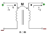
in a circuit. This property also is called self-inductance to discriminate it from mutual inductance, describing the voltage induced in one electrical circuit by the rate of change of the electric current in another circuit.
The quantitative definition of the self inductance L of an electrical circuit in SI
Si
Si, si, or SI may refer to :- Measurement, mathematics and science :* International System of Units , the modern international standard version of the metric system...
units
Units of measurement
A unit of measurement is a definite magnitude of a physical quantity, defined and adopted by convention and/or by law, that is used as a standard for measurement of the same physical quantity. Any other value of the physical quantity can be expressed as a simple multiple of the unit of...
(webers
Weber (unit)
In physics, the weber is the SI unit of magnetic flux. A flux density of one Wb/m2 is one tesla.The weber is named for the German physicist Wilhelm Eduard Weber .- Definition :...
per ampere
Ampere
The ampere , often shortened to amp, is the SI unit of electric current and is one of the seven SI base units. It is named after André-Marie Ampère , French mathematician and physicist, considered the father of electrodynamics...
, known as henries) is

where v denotes the voltage in volts and i the current in amperes.