
Air Traffic Control Radar Beacon System
Encyclopedia
The air traffic control radar beacon system (ATCRBS) is a system used in air traffic control
(ATC) to enhance surveillance radar
monitoring and separation of air traffic. ATCRBS assists ATC surveillance radars by acquiring information about the aircraft
being monitored, and providing this information to the radar controllers. The controllers can use the information to identify radar returns from aircraft (known as targets) and to distinguish those returns from ground clutter
.
s, installed in aircraft, and secondary surveillance radar
s (SSRs), installed at air traffic control facilities. The SSR is co-located with the primary surveillance radar, or PSR. These two radar systems work in conjunction to produce a synchronized surveillance picture. The SSR transmits interrogations and listens for any replies. Transponders that receive an interrogation decode it, decide whether to reply, and then respond with the requested information when appropriate. Note that in common informal usage, the term "SSR" is sometimes used to refer to the entire ATCRBS system, however this term (as found in technical publications) properly refers only to the ground radar itself.
The second system is the secondary surveillance radar, or SSR, which depends on a cooperating transponder
installed on the aircraft being tracked. The transponder emits a signal when it is swept by the secondary radar. In a transponder based system signals drop off as the inverse square of the distance to the target, instead of the fourth power in primary radars. As a result, effective range is greatly increased for a given power level. The transponder can also send encoded information about the aircraft, such as identity and altitude.
The SSR is equipped with a main antenna
, and an omnidirectional
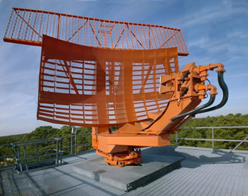
"Omni" antenna at many older sites. Newer antennas (like the picture to the right), are grouped as a left and right antenna, and each side connects to a hybrid device which combines the signals into sum and difference channels. Still other sites have both the sum and difference antenna, and an Omni antenna. Surveillance aircraft, e.g. AWACS, have only the sum and difference antennas, but can also be space stabilized by phase shifting the beam down or up when pitched or banking. The SSR beam antenna is typically fitted to the PSR antenna, so that they point in the same direction as the antennas rotate. The omnidirectional antenna is mounted near and high, and usually on top of the radome if equipped. Mode-S interrogators require the sum and difference channels to provide the monopulse
capability to measure the off-boresight angle of the transponder reply.
The SSR repetitively transmits interrogations as the rotating radar scans the sky. The interrogation specifies what type of information a replying transponder should send by using a system of modes. There have been a number of modes used historically, but four are in common use today: mode 1, mode 2, mode 3/A, and mode C. Mode 1 is used to sort military targets during phases of a mission. Mode 2 is used to identify military aircraft missions. Mode 3/A is used to identify each aircraft in the radar's coverage area. Mode C is used to request an aircraft's altitude.
Two other modes, mode 4 and mode S, are not considered part of the ATCRBS system, but they use the same transmit and receive hardware. Mode 4 is used by military aircraft for the Identification Friend or Foe (IFF) system. Mode S is a discrete selective interrogation rather than a general broadcast, that facilitates TCAS for civil aircraft. Mode S transponders ignore interrogations not addressed with their unique identity code, reducing channel congestion. At a typical SSR radar installation, ATCRBS, IFF, and mode S interrogations will all be transmitted in an interlaced fashion.
Returns from both radars at the ground station are transmitted to the ATC facility using a microwave
link, a coaxial
link, or (with newer radars) a digitizer and a modem
. Once received at the ATC facility, a computer system known as a radar data processor associates the reply information with the proper primary target and displays it next to the target on the radar scope.
rack, and a small L band
UHF
antenna, mounted on the bottom of the fuselage
. Many commercial aircraft also have an antenna on the top of the fuselage, and either or both antennas can be selected by the flight crew.
Typical installations also include an altitude encoder
, which is a small device connected to both the transponder and the aircraft's static system. It provides the aircraft's pressure altitude
to the transponder, so that it may relay the information to the ATC facility. The encoder uses 11 wires to pass the height information to the transponder in the form of a Gillham Code
, a modified binary Gray code.
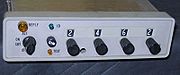 The transponder has a small required set of controls and is simple to operate. It has a method to enter the four-digit transponder code, also known as a beacon code or squawk code, and a control to transmit an ident, which is done at the controller's request (see SPI pulse below). Transponders typically have 4 operating modes: Off, Standby, On (Mode-A), and Alt (Mode-C). On and Alt mode differ only in that the On mode inhibits transmitting any altitude information. Standby mode allows the unit to remain powered and warmed up but inhibits any replies, since older transponders incorporate transmitter
s which must be warmed up before they will function.
Mode 3/A uses a P1 to P3 spacing of 8.0 μs, and is used to request the beacon code, which was assigned to the aircraft by the controller to identify it. Mode C uses a spacing of 21 μs, and requests the aircraft's pressure altitude, provided by the altitude encoder. Mode 2 uses a spacing of 5 μs and requests the aircraft to transmit its Military identification code. The latter is only assigned to Military aircraft and so only a small percentage of aircraft actually reply to a mode 2 interrogation.
F1 C1 A1 C2 A2 C4 A4 X B1 D1 B2 D2 B4 D4 F2 SPI
The F1 and F2 pulses are framing
pulses, and are always transmitted by the aircraft transponder. They are used by the interrogator to identify legitimate replies. These are spaced 20.3 μs apart.
The A4, A2, A1, B4, B2, B1, C4, C2, C1, D4, D2, D1 pulses constitute the "information" contained in the reply. These bits are used in different ways for each interrogation mode.
For mode A, each digit in the transponder code (A, B, C, or D) may be a number from zero to seven. These octal
digits are transmitted as groups of three pulses each, the A slots reserved for the first digit, B for the second, and so on.
In a mode C reply, the altitude is encoded by a Gillham interface, Gillham Code
, which uses gray code
. The Gillham interface is capable of representing a wide range of altitudes, in 100 feet (30.5 m) increments. The altitude transmitted is pressure altitude, and corrected for altimeter
setting at the ATC facility. If no encoder is attached, the transponder may optionally transmit only framing pulses (most modern transponders do).
In a mode 3 reply, the information is similar to the mode A reply in that there are 4 digits transmitted between 0 and 7. The mode 3 reply differs from the mode A reply in that the transmitted code is assigned by a military air traffic controller, not a civilian air traffic controller.
The X bit is currently only used for test targets. This bit was originally transmitted by BOMARC missiles
that were used as air launched test targets. This bit may be used by drone aircraft.
The SPI pulse is positioned 4.35μs past the F2 pulse (3 time slots) and is used as a "Special Identification Pulse". The SPI pulse is turned on by the "identity control" on the transponder in the aircraft cockpit when requested by air traffic control. The air traffic controller can request the pilot to ident, and when the identity control is activated, the SPI bit will be added to the reply for about 20 seconds (two to four rotations of the interrogator antenna) thereby highlighting the track on the controllers display.
s. When aircraft are close to the ground station, the side lobe signals are often strong enough to elicit a reply from their transponders when the antenna is not pointing at them. This can cause ghosting, where an aircraft's target may appear in more than one location on the radar scope. In extreme cases, an effect known as ring-around occurs, where the transponder replies to excess resulting in an arc or circle of replies centered on the radar site.
To combat these effects, side lobe suppression (SLS) is used. SLS employs a third pulse, P2, spaced 2μs after P1. This pulse is transmitted from the omnidirectional antenna (or the antenna difference channel) by the ground station, rather than from the directional antenna (or the sum channel). The power output from the omnidirectional antenna is calibrated so that, when received by an aircraft, the P2 pulse is stronger than either P1 or P3, except when the directional antenna is pointing directly at the aircraft. By comparing the relative strengths of P2 and P1, airborne transponders can determine whether or not the antenna is pointing at the aircraft when the interrogation was received. The power to the difference antenna pattern (for systems so equipped) is not adjusted from that of the P1 and P3 pulses. Algorithms are used in the ground receivers to delete replies on the edge of the two beam patterns.
To combat these effects more recently, side lobe suppression (SLS) is still used, but differently. The new and improved SLS employs a third pulse, spaced 2μs either before P3 (a new P2 position) or after P3 (which should be called P4 and appears in the Mode S radar and TCAS specifications). This pulse is transmitted from the directional antenna at the ground station, and the power output of this pulse is the same strength as the P1 and P3 pulses. The action to be taken is specified in the new and improved C74c as:
2.6 Decoding Performance.
c. Side-lobe Suppression. The transponder must be suppressed for a period of 35 ±10 microseconds following receipt of a pulse pair of proper spacing and suppression action must be capable of being reinitiated for the full duration within 2 microseconds after the end of any suppression period. The transponder must be suppressed with a 99 percent efficiency over a received signal amplitude range between 3 db above minimum triggering level and 50 db above that level and upon receipt of properly spaced interrogations when the received amplitude of P2 is equal to or in excess of the received amplitude of P1 and spaced 2.0 ±0.15 microsecond from P3.
Any requirement at the transponder to detect and act upon a P2 pulse 2μs after P1 has been removed from the new and improved TSO C74c specification.
Most "modern" transponders (manufactured since 1973) have an "SLS" circuit which suppresses reply on receipt of any two pulses in any interrogation spaced 2.0 microseconds apart that are above the MTL Minimum Triggering Level threshold of the receiver amplitude descriminator (P1->P2 or P2->P3 or P3->P4). This approach was used to comply with the original C74c and but also complies with the provisions of the new and improved C74c.
The FAA refers to the non-responsiveness of new and improved TSO C74c compliant transponders to Mode S compatible radars and TCAS as "The Terra Problem", and has issued Airworthiness Directives (ADs) against various transponder manufacturers, over the years, at various times on no predictable schedule. The ghosting and ring around problems have recurred on the more modern radars.
To combat these effects most recently, great emphasis is placed upon software solutions. It is highly likely that one of those software algorithms was the proximate cause of a mid-air collision recently, as one airplane was reported at showing its altitude as the pre-flight paper filed flight plan, and not the altitude assigned by the ATC controller (see the reports and observations contained in the below reference ATC Controlled Airplane Passenger Study of how radar worked).
See the reference section below for errors in performance standards for ATCRBS transponders in the US.
See the reference section below for FAA Technician Study of in-situ transponders.
s, and when that beacon code is received from an aircraft, the computer can associate it with flight plan information to display immediately useful data, such as aircraft callsign, the aircraft's next navigational fix, assigned and current altitude, etc. near the target in a data block.
Mode S, despite being called a replacement transponder system for ATCRBS, is actually a data packet protocol which can be used to augment ATCRBS transponder positioning equipment (radar and TCAS).
One major improvement of Mode S, is the ability to interrogate a single aircraft at a time. With old ATCRBS technology, all aircraft within the beam pattern of the interrogating station will reply. In an airspace with multiple interrogation stations, ATCRBS transponders in aircraft can be overwhelmed. By interrogating one aircraft at a time, workload on the aircraft transponder is greatly reduced.
The second major improvement is increased azimuth accuracy. With PSRs and old SSRs, azimuth of the aircraft is determined by the half split (centroid) method. The half split method is computed by recording the azimuth of the first and last replies from the aircraft, as the radar beam sweeps past its position. Then the mid-point between the start and stop azimuth is used for aircraft position. With MSSR (Monopulse Secondary Surveillance Radar) and Mode S, the radar can use the information of one reply to determine azimuth. This is calculated based on the RF phase of the aircraft reply, as determined by the sum and difference antenna elements, and is called monopulse. This monopulse method results in superior azimuth resolution, and removes target jitter from the display.
The Mode S system also includes a more robust communications protocol, for a wider variety of information exchange. At this time, this capability is becoming mandatory across Europe with some states already requiring its use.
Air traffic control
Air traffic control is a service provided by ground-based controllers who direct aircraft on the ground and in the air. The primary purpose of ATC systems worldwide is to separate aircraft to prevent collisions, to organize and expedite the flow of traffic, and to provide information and other...
(ATC) to enhance surveillance radar
Radar
Radar is an object-detection system which uses radio waves to determine the range, altitude, direction, or speed of objects. It can be used to detect aircraft, ships, spacecraft, guided missiles, motor vehicles, weather formations, and terrain. The radar dish or antenna transmits pulses of radio...
monitoring and separation of air traffic. ATCRBS assists ATC surveillance radars by acquiring information about the aircraft
Aircraft
An aircraft is a vehicle that is able to fly by gaining support from the air, or, in general, the atmosphere of a planet. An aircraft counters the force of gravity by using either static lift or by using the dynamic lift of an airfoil, or in a few cases the downward thrust from jet engines.Although...
being monitored, and providing this information to the radar controllers. The controllers can use the information to identify radar returns from aircraft (known as targets) and to distinguish those returns from ground clutter
Clutter (radar)
Clutter is a term used for unwanted echoes in electronic systems, particularly in reference to radars. Such echoes are typically returned from ground, sea, rain, animals/insects, chaff and atmospheric turbulences, and can cause serious performance issues with radar systems.- Backscatter coefficient...
.
Parts of the system
The system consists of transponderTransponder (aviation)
A transponder is an electronic device that produces a response when it receives a radio-frequency interrogation...
s, installed in aircraft, and secondary surveillance radar
Secondary surveillance radar
Secondary surveillance radar is a radar system used in air traffic control , that not only detects and measures the position of aircraft i.e. range and bearing, but also requests additional information from the aircraft itself such as its identity and altitude...
s (SSRs), installed at air traffic control facilities. The SSR is co-located with the primary surveillance radar, or PSR. These two radar systems work in conjunction to produce a synchronized surveillance picture. The SSR transmits interrogations and listens for any replies. Transponders that receive an interrogation decode it, decide whether to reply, and then respond with the requested information when appropriate. Note that in common informal usage, the term "SSR" is sometimes used to refer to the entire ATCRBS system, however this term (as found in technical publications) properly refers only to the ground radar itself.
Ground Interrogation Equipment
An ATC ground station consists of two radar systems and their associated support components. The most prominent component is the PSR. It is also sometimes referred to as skin paint radar because it operates using traditional radar principles, transmitting radio pulses and listening for and timing the reflections from the skin or other metal components of aircraft. The primary surveillance radar is subject to the radar equation that says signal strength drops off as the fourth power of distance to the target. Objects detected using the PSR are known as primary targets.The second system is the secondary surveillance radar, or SSR, which depends on a cooperating transponder
Transponder (aviation)
A transponder is an electronic device that produces a response when it receives a radio-frequency interrogation...
installed on the aircraft being tracked. The transponder emits a signal when it is swept by the secondary radar. In a transponder based system signals drop off as the inverse square of the distance to the target, instead of the fourth power in primary radars. As a result, effective range is greatly increased for a given power level. The transponder can also send encoded information about the aircraft, such as identity and altitude.
The SSR is equipped with a main antenna
Antenna (radio)
An antenna is an electrical device which converts electric currents into radio waves, and vice versa. It is usually used with a radio transmitter or radio receiver...
, and an omnidirectional
Omnidirectional antenna
In radio communication, an omnidirectional antenna is an antenna which radiates radio wave power uniformly in all directions in one plane, with the radiated power decreasing with elevation angle above or below the plane, dropping to zero on the antenna's axis. This radiation pattern is often...
"Omni" antenna at many older sites. Newer antennas (like the picture to the right), are grouped as a left and right antenna, and each side connects to a hybrid device which combines the signals into sum and difference channels. Still other sites have both the sum and difference antenna, and an Omni antenna. Surveillance aircraft, e.g. AWACS, have only the sum and difference antennas, but can also be space stabilized by phase shifting the beam down or up when pitched or banking. The SSR beam antenna is typically fitted to the PSR antenna, so that they point in the same direction as the antennas rotate. The omnidirectional antenna is mounted near and high, and usually on top of the radome if equipped. Mode-S interrogators require the sum and difference channels to provide the monopulse
Monopulse radar
Monopulse radar is an adaptation of conical scanning radar which sends additional information in the radar signal in order to avoid problems caused by rapid changes in signal strength. The system also makes jamming more difficult...
capability to measure the off-boresight angle of the transponder reply.
The SSR repetitively transmits interrogations as the rotating radar scans the sky. The interrogation specifies what type of information a replying transponder should send by using a system of modes. There have been a number of modes used historically, but four are in common use today: mode 1, mode 2, mode 3/A, and mode C. Mode 1 is used to sort military targets during phases of a mission. Mode 2 is used to identify military aircraft missions. Mode 3/A is used to identify each aircraft in the radar's coverage area. Mode C is used to request an aircraft's altitude.
Two other modes, mode 4 and mode S, are not considered part of the ATCRBS system, but they use the same transmit and receive hardware. Mode 4 is used by military aircraft for the Identification Friend or Foe (IFF) system. Mode S is a discrete selective interrogation rather than a general broadcast, that facilitates TCAS for civil aircraft. Mode S transponders ignore interrogations not addressed with their unique identity code, reducing channel congestion. At a typical SSR radar installation, ATCRBS, IFF, and mode S interrogations will all be transmitted in an interlaced fashion.
Returns from both radars at the ground station are transmitted to the ATC facility using a microwave
Microwave
Microwaves, a subset of radio waves, have wavelengths ranging from as long as one meter to as short as one millimeter, or equivalently, with frequencies between 300 MHz and 300 GHz. This broad definition includes both UHF and EHF , and various sources use different boundaries...
link, a coaxial
Coaxial cable
Coaxial cable, or coax, has an inner conductor surrounded by a flexible, tubular insulating layer, surrounded by a tubular conducting shield. The term coaxial comes from the inner conductor and the outer shield sharing the same geometric axis...
link, or (with newer radars) a digitizer and a modem
Modem
A modem is a device that modulates an analog carrier signal to encode digital information, and also demodulates such a carrier signal to decode the transmitted information. The goal is to produce a signal that can be transmitted easily and decoded to reproduce the original digital data...
. Once received at the ATC facility, a computer system known as a radar data processor associates the reply information with the proper primary target and displays it next to the target on the radar scope.
Airborne Transponder Equipment
The equipment installed in the aircraft is considerably simpler, consisting of the transponder itself, usually mounted in the instrument panel or avionicsAvionics
Avionics are electronic systems used on aircraft, artificial satellites and spacecraft.Avionic systems include communications, navigation, the display and management of multiple systems and the hundreds of systems that are fitted to aircraft to meet individual roles...
rack, and a small L band
L band
L band refers to four different bands of the electromagnetic spectrum: 40 to 60 GHz , 1 to 2 GHz , 1565 nm to 1625 nm , and around 3.5 micrometres .-NATO L band:...
UHF
Ultra high frequency
Ultra-High Frequency designates the ITU Radio frequency range of electromagnetic waves between 300 MHz and 3 GHz , also known as the decimetre band or decimetre wave as the wavelengths range from one to ten decimetres...
antenna, mounted on the bottom of the fuselage
Fuselage
The fuselage is an aircraft's main body section that holds crew and passengers or cargo. In single-engine aircraft it will usually contain an engine, although in some amphibious aircraft the single engine is mounted on a pylon attached to the fuselage which in turn is used as a floating hull...
. Many commercial aircraft also have an antenna on the top of the fuselage, and either or both antennas can be selected by the flight crew.
Typical installations also include an altitude encoder
Encoder
An encoder is a device, circuit, transducer, software program, algorithm or person that converts information from one format or code to another, for the purposes of standardization, speed, secrecy, security, or saving space by shrinking size.-Media:...
, which is a small device connected to both the transponder and the aircraft's static system. It provides the aircraft's pressure altitude
Pressure altitude
In aviation, pressure altitude is the indicated altitude when an altimeter is set to an agreed baseline pressure setting. The baseline pressure is 1013.25 hPa, equivalent to 1013.25 millibar, or 29.92 inches of mercury. This setting is equivalent to the air pressure at mean sea level in the...
to the transponder, so that it may relay the information to the ATC facility. The encoder uses 11 wires to pass the height information to the transponder in the form of a Gillham Code
Gillham Code
Gillham code is a digital code using an eleven-wire interface that is used to transmit uncorrected barometric altitude between an encoding altimeter or analog air data computer and a transponder...
, a modified binary Gray code.
Transmitter
In electronics and telecommunications a transmitter or radio transmitter is an electronic device which, with the aid of an antenna, produces radio waves. The transmitter itself generates a radio frequency alternating current, which is applied to the antenna. When excited by this alternating...
s which must be warmed up before they will function.
Theory of operation
The steps involved in performing an ATCRBS interrogation are as follows: First, the ATCRBS interrogator periodically interrogates aircraft on a frequency of 1030 MHz. This is done through a rotating or scanning antenna at the radar's assigned Pulse Repetition Frequency (PRF). Interrogations are typically performed at 450 - 500 interrogations/second. Once an interrogation has been transmitted, it travels through space in the direction the antenna is pointing at the speed of light until an aircraft is reached. When the aircraft receives the interrogation, the aircraft transponder will send a reply on 1090 MHz after a 3.0 μs delay indicating the requested information. The interrogator's processor will then decode the reply and identify the aircraft. The range of the aircraft is determined from the delay between the reply and the interrogation. The azimuth of the aircraft is determined from the direction the antenna is pointing when the first reply was received, until the last reply is received. This window of azimuth values is then divided by two to give the calculated "centroid" azimuth. The errors in this algorithm cause the aircraft to jitter across the controllers scope, and is referred to as "track jitter." The jitter problem makes software tracking algorithms problematic, and is the reason why monopulse was implemented.The interrogation
Interrogations consist of three pulses, 0.8 μs in duration, referred to as P1, P2 and P3. The timing between pulses P1 and P3 determines the mode (or question) of the interrogation, and thus what the nature of the reply should be. P2 is used in side-lobe suppression, explained later.Mode 3/A uses a P1 to P3 spacing of 8.0 μs, and is used to request the beacon code, which was assigned to the aircraft by the controller to identify it. Mode C uses a spacing of 21 μs, and requests the aircraft's pressure altitude, provided by the altitude encoder. Mode 2 uses a spacing of 5 μs and requests the aircraft to transmit its Military identification code. The latter is only assigned to Military aircraft and so only a small percentage of aircraft actually reply to a mode 2 interrogation.
The reply
Replies to interrogations consist of 15 time slots, each 1.45 μs in width. The reply is encoded by the presence or absence of a 0.45 μs pulse in each slot. These are labeled as follows:F1 C1 A1 C2 A2 C4 A4 X B1 D1 B2 D2 B4 D4 F2 SPI
The F1 and F2 pulses are framing
Frame synchronization
While receiving a stream of framed data, frame synchronization is the process by which incoming frame alignment signals, i.e., distinctive bit sequences , are identified, i.e., distinguished from data bits, permitting the data bits within the frame to be extracted for decoding or retransmission...
pulses, and are always transmitted by the aircraft transponder. They are used by the interrogator to identify legitimate replies. These are spaced 20.3 μs apart.
The A4, A2, A1, B4, B2, B1, C4, C2, C1, D4, D2, D1 pulses constitute the "information" contained in the reply. These bits are used in different ways for each interrogation mode.
For mode A, each digit in the transponder code (A, B, C, or D) may be a number from zero to seven. These octal
Octal
The octal numeral system, or oct for short, is the base-8 number system, and uses the digits 0 to 7. Numerals can be made from binary numerals by grouping consecutive binary digits into groups of three...
digits are transmitted as groups of three pulses each, the A slots reserved for the first digit, B for the second, and so on.
In a mode C reply, the altitude is encoded by a Gillham interface, Gillham Code
Gillham Code
Gillham code is a digital code using an eleven-wire interface that is used to transmit uncorrected barometric altitude between an encoding altimeter or analog air data computer and a transponder...
, which uses gray code
Gray code
The reflected binary code, also known as Gray code after Frank Gray, is a binary numeral system where two successive values differ in only one bit. It is a non-weighted code....
. The Gillham interface is capable of representing a wide range of altitudes, in 100 feet (30.5 m) increments. The altitude transmitted is pressure altitude, and corrected for altimeter
Altimeter
An altimeter is an instrument used to measure the altitude of an object above a fixed level. The measurement of altitude is called altimetry, which is related to the term bathymetry, the measurement of depth underwater.-Pressure altimeter:...
setting at the ATC facility. If no encoder is attached, the transponder may optionally transmit only framing pulses (most modern transponders do).
In a mode 3 reply, the information is similar to the mode A reply in that there are 4 digits transmitted between 0 and 7. The mode 3 reply differs from the mode A reply in that the transmitted code is assigned by a military air traffic controller, not a civilian air traffic controller.
The X bit is currently only used for test targets. This bit was originally transmitted by BOMARC missiles
Bomarc Missile Program
The CIM-10 Bomarc was the only surface-to-air missile ever deployed by the United States Air Force. All other U.S. land-based SAMs were and are under the control of the United States Army....
that were used as air launched test targets. This bit may be used by drone aircraft.
The SPI pulse is positioned 4.35μs past the F2 pulse (3 time slots) and is used as a "Special Identification Pulse". The SPI pulse is turned on by the "identity control" on the transponder in the aircraft cockpit when requested by air traffic control. The air traffic controller can request the pilot to ident, and when the identity control is activated, the SPI bit will be added to the reply for about 20 seconds (two to four rotations of the interrogator antenna) thereby highlighting the track on the controllers display.
Side lobe suppression
The SSR's directional antenna is never perfect; inevitably it will "leak" lower levels of RF energy in off-axis directions. These are known as side lobeSide lobe
In antenna engineering, side lobes or sidelobes are the lobes of the far field radiation pattern that are not the main lobe....
s. When aircraft are close to the ground station, the side lobe signals are often strong enough to elicit a reply from their transponders when the antenna is not pointing at them. This can cause ghosting, where an aircraft's target may appear in more than one location on the radar scope. In extreme cases, an effect known as ring-around occurs, where the transponder replies to excess resulting in an arc or circle of replies centered on the radar site.
To combat these effects, side lobe suppression (SLS) is used. SLS employs a third pulse, P2, spaced 2μs after P1. This pulse is transmitted from the omnidirectional antenna (or the antenna difference channel) by the ground station, rather than from the directional antenna (or the sum channel). The power output from the omnidirectional antenna is calibrated so that, when received by an aircraft, the P2 pulse is stronger than either P1 or P3, except when the directional antenna is pointing directly at the aircraft. By comparing the relative strengths of P2 and P1, airborne transponders can determine whether or not the antenna is pointing at the aircraft when the interrogation was received. The power to the difference antenna pattern (for systems so equipped) is not adjusted from that of the P1 and P3 pulses. Algorithms are used in the ground receivers to delete replies on the edge of the two beam patterns.
To combat these effects more recently, side lobe suppression (SLS) is still used, but differently. The new and improved SLS employs a third pulse, spaced 2μs either before P3 (a new P2 position) or after P3 (which should be called P4 and appears in the Mode S radar and TCAS specifications). This pulse is transmitted from the directional antenna at the ground station, and the power output of this pulse is the same strength as the P1 and P3 pulses. The action to be taken is specified in the new and improved C74c as:
2.6 Decoding Performance.
c. Side-lobe Suppression. The transponder must be suppressed for a period of 35 ±10 microseconds following receipt of a pulse pair of proper spacing and suppression action must be capable of being reinitiated for the full duration within 2 microseconds after the end of any suppression period. The transponder must be suppressed with a 99 percent efficiency over a received signal amplitude range between 3 db above minimum triggering level and 50 db above that level and upon receipt of properly spaced interrogations when the received amplitude of P2 is equal to or in excess of the received amplitude of P1 and spaced 2.0 ±0.15 microsecond from P3.
Any requirement at the transponder to detect and act upon a P2 pulse 2μs after P1 has been removed from the new and improved TSO C74c specification.
Most "modern" transponders (manufactured since 1973) have an "SLS" circuit which suppresses reply on receipt of any two pulses in any interrogation spaced 2.0 microseconds apart that are above the MTL Minimum Triggering Level threshold of the receiver amplitude descriminator (P1->P2 or P2->P3 or P3->P4). This approach was used to comply with the original C74c and but also complies with the provisions of the new and improved C74c.
The FAA refers to the non-responsiveness of new and improved TSO C74c compliant transponders to Mode S compatible radars and TCAS as "The Terra Problem", and has issued Airworthiness Directives (ADs) against various transponder manufacturers, over the years, at various times on no predictable schedule. The ghosting and ring around problems have recurred on the more modern radars.
To combat these effects most recently, great emphasis is placed upon software solutions. It is highly likely that one of those software algorithms was the proximate cause of a mid-air collision recently, as one airplane was reported at showing its altitude as the pre-flight paper filed flight plan, and not the altitude assigned by the ATC controller (see the reports and observations contained in the below reference ATC Controlled Airplane Passenger Study of how radar worked).
See the reference section below for errors in performance standards for ATCRBS transponders in the US.
See the reference section below for FAA Technician Study of in-situ transponders.
Radar display
The beacon code and altitude were historically displayed verbatim on the radar scope next to the target, however modernization has extended the radar data processor with a flight data processor, or FDP. The FDP automatically assigns beacon codes to flight planFlight plan
Flight plans are documents filed by pilots or a Flight Dispatcher with the local Civil Aviation Authority prior to departure...
s, and when that beacon code is received from an aircraft, the computer can associate it with flight plan information to display immediately useful data, such as aircraft callsign, the aircraft's next navigational fix, assigned and current altitude, etc. near the target in a data block.
Mode S
Mode S, or mode select, despite also being called a mode, is actually a radically improved system intended to replace ATCRBS altogether. A few countries have mandated mode S, and many other countries, including the United States, have begun phasing out ATCRBS in favor of this system. Mode S is designed to be fully backward compatible with existing ATCRBS technology.Mode S, despite being called a replacement transponder system for ATCRBS, is actually a data packet protocol which can be used to augment ATCRBS transponder positioning equipment (radar and TCAS).
One major improvement of Mode S, is the ability to interrogate a single aircraft at a time. With old ATCRBS technology, all aircraft within the beam pattern of the interrogating station will reply. In an airspace with multiple interrogation stations, ATCRBS transponders in aircraft can be overwhelmed. By interrogating one aircraft at a time, workload on the aircraft transponder is greatly reduced.
The second major improvement is increased azimuth accuracy. With PSRs and old SSRs, azimuth of the aircraft is determined by the half split (centroid) method. The half split method is computed by recording the azimuth of the first and last replies from the aircraft, as the radar beam sweeps past its position. Then the mid-point between the start and stop azimuth is used for aircraft position. With MSSR (Monopulse Secondary Surveillance Radar) and Mode S, the radar can use the information of one reply to determine azimuth. This is calculated based on the RF phase of the aircraft reply, as determined by the sum and difference antenna elements, and is called monopulse. This monopulse method results in superior azimuth resolution, and removes target jitter from the display.
The Mode S system also includes a more robust communications protocol, for a wider variety of information exchange. At this time, this capability is becoming mandatory across Europe with some states already requiring its use.