
Radar
Overview
Radio Wave
Radio Wave may refer to:*Radio frequency*Radio Wave 96.5, a radio station in Blackpool, UK...
s to determine the range, altitude, direction, or speed of objects. It can be used to detect aircraft
Aircraft
An aircraft is a vehicle that is able to fly by gaining support from the air, or, in general, the atmosphere of a planet. An aircraft counters the force of gravity by using either static lift or by using the dynamic lift of an airfoil, or in a few cases the downward thrust from jet engines.Although...
, ships, spacecraft
Spacecraft
A spacecraft or spaceship is a craft or machine designed for spaceflight. Spacecraft are used for a variety of purposes, including communications, earth observation, meteorology, navigation, planetary exploration and transportation of humans and cargo....
, guided missiles, motor vehicle
Motor vehicle
A motor vehicle or road vehicle is a self-propelled wheeled vehicle that does not operate on rails, such as trains or trolleys. The vehicle propulsion is provided by an engine or motor, usually by an internal combustion engine, or an electric motor, or some combination of the two, such as hybrid...
s, weather formations
Weather radar
Weather radar, also called weather surveillance radar and Doppler weather radar, is a type of radar used to locate precipitation, calculate its motion, estimate its type . Modern weather radars are mostly pulse-Doppler radars, capable of detecting the motion of rain droplets in addition to the...
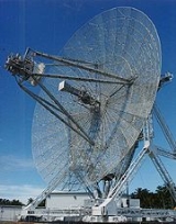
, and terrain. The radar dish or antenna transmits pulses of radio waves or microwave
Microwave
Microwaves, a subset of radio waves, have wavelengths ranging from as long as one meter to as short as one millimeter, or equivalently, with frequencies between 300 MHz and 300 GHz. This broad definition includes both UHF and EHF , and various sources use different boundaries...
s which bounce off any object in their path. The object returns a tiny part of the wave's energy to a dish or antenna which is usually located at the same site as the transmitter.
Radar was developed in secret in nations across the world during World War II
World War II
World War II, or the Second World War , was a global conflict lasting from 1939 to 1945, involving most of the world's nations—including all of the great powers—eventually forming two opposing military alliances: the Allies and the Axis...
.
Unanswered Questions