
.gif)
Clutter (radar)
Encyclopedia
Clutter is a term used for unwanted echoes in electronic systems, particularly in reference to radar
s. Such echoes are typically returned from ground, sea, rain, animals/insects, chaff
and atmospheric turbulence
s, and can cause serious performance issues with radar systems.
 , is within a rainstorm. What is the effect on the detectability of the target?
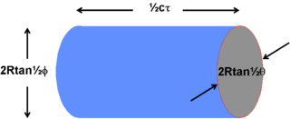 First find the magnitude of the clutter return. Assume that the clutter fills the cell containing the target, that scatterers are statistically independent and that the scatterers are uniformly distributed through the volume. The clutter volume illuminated by a pulse can be calculated from the beam widths and the pulse duration, Figure 1. If c is the velocity of light and
  is the time duration of the transmitted pulse then the pulse returning from a target is equivalent to a physical extent of c
 , as is the return from any individual element of the clutter. The azimuth and elevation beamwidths, at a range
  , are
, are  and
and  respectively if the illuminated cell is assumed to have an elliptical cross section.
The volume of the illuminated cell is thus:

For small angles this simplifies to:

The clutter is assumed to be a large number of independent scatterers that fill the cell containing the target uniformly. The clutter return from the volume is calculated as for the normal radar equation but the radar cross section
is replaced by the product of the volume backscatter coefficient, , and the clutter cell volume as derived above. The clutter return is then
 Watts
Watts
where
A correction must be made to allow for the fact that the illumination of the clutter is not uniform across the beamwidth. In practice the beam shape will approximate to a sinc function which itself approximates to a Gaussian function. The correction factor is found by integrating across the beam width the Gaussian approximation of the antenna. The corrected back scattered power is
 Watts
Watts
A number of simpliflying substitutions can be made.
The receiving antenna aperture is related to its gain by:

and the antenna gain
is related to the two beamwidths by:

The same antenna is generally used both for transmission and reception thus the received clutter power is:
 Watts
Watts
If the Clutter Return Power is greater than the System Noise Power then the Radar is clutter limited and the Signal to Clutter Ratio must be equal to or greater than the Minimum Signal to Noise Ratio for the target to be detectable.
From the radar equation the return from the target itself will be
 Watts
Watts
with a resulting expression for the signal to clutter ratio of
The implication is that when the radar is noise limited the variation of signal to noise ratio is an inverse fourth power. Halving the distance will cause the signal to noise ratio to increase (improve) by a factor of 16. When the radar is volume clutter limited, however, the variation is an inverse square law and halving the distance will cause the signal to clutter to improve by only 4 times.
Since

it follows that
Clearly narrow beamwidths and short pulses are required to reduce the effect of clutter by reducing the volume of the clutter cell. If pulse compression
is used then the appropriate pulse duration to be used in the calculation is that of the compressed pulse, not the transmitted pulse.
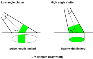 For a target close to the Earth's surface such that the earth and target are in the same range resolution cell one of two conditions are possible. The most common case is when the beam intersects the surface at such an angle that the area illuminated at any one time is only a fraction of the surface intersected by the beam as illustrated in Figure 2.
 .
.
The length measured along the surface is
 .
.
The area illuminated by the radar is then given by

For 'small' beamwidths this approximates to

The clutter return is then
 Watts
Watts
Substituting for the illuminated area
 Watts
Watts
where is the back scatter coefficient of the clutter.
Converting to degrees and putting in the numerical values gives
 Watts
Watts
The expression for the target return remains unchanged thus the signal to clutter ratio is
 Watts
Watts
This simplifies to

In the case of surface clutter the signal to clutter now varies inversely with R. Halving the distance only causes a doubling of the ratio (a factor of two improvement).

which for small beamwidths simplifies to

The clutter return is as before
 Watts
Watts
Substituting for the illuminated area
 Watts
Watts
This can be simplified to:
 Watts
Watts
Converting to degrees
 Watts
Watts
The target return remains unchanged thus
Which simplifies to
As in the case of Volume Clutter the Signal to clutter ratio follows an inverse square law.
Radar
Radar is an object-detection system which uses radio waves to determine the range, altitude, direction, or speed of objects. It can be used to detect aircraft, ships, spacecraft, guided missiles, motor vehicles, weather formations, and terrain. The radar dish or antenna transmits pulses of radio...
s. Such echoes are typically returned from ground, sea, rain, animals/insects, chaff
Chaff (radar countermeasure)
Chaff, originally called Window by the British, and Düppel by the Second World War era German Luftwaffe , is a radar countermeasure in which aircraft or other targets spread a cloud of small, thin pieces of aluminium, metallized glass fibre or plastic, which either appears as a cluster of secondary...
and atmospheric turbulence
Turbulence
In fluid dynamics, turbulence or turbulent flow is a flow regime characterized by chaotic and stochastic property changes. This includes low momentum diffusion, high momentum convection, and rapid variation of pressure and velocity in space and time...
s, and can cause serious performance issues with radar systems.
Backscatter coefficient
What is considered to be clutter by one user may be a target for another. Usually targets may be considered to be a point scatterer and clutter as extended, covering many range, angle and Doppler cells. The clutter may fill a volume (rain) or be confined to a surface (land). In principle all that is required to estimate the return (backscatter) is a knowledge of the volume or surface illuminated and the echo per unit volume, η, or per unit surface area, σ°, (the backscatter coefficient).Clutter or Noise limited radar
In addition to any possible clutter there will also always be noise. The total signal competing with the target return is thus clutter plus noise. In practice there is often either no clutter or clutter dominates and the noise can be ignored. In the first case the radar is said to be Noise Limited, in the second it is Clutter Limited.Volume Clutter
Rain, hail, snow and chaff are examples of volume clutter. An airborne target, at range, is within a rainstorm. What is the effect on the detectability of the target? is the time duration of the transmitted pulse then the pulse returning from a target is equivalent to a physical extent of c, as is the return from any individual element of the clutter. The azimuth and elevation beamwidths, at a range , are and respectively if the illuminated cell is assumed to have an elliptical cross section.The volume of the illuminated cell is thus:
For small angles this simplifies to:
The clutter is assumed to be a large number of independent scatterers that fill the cell containing the target uniformly. The clutter return from the volume is calculated as for the normal radar equation but the radar cross section
Radar cross section
Radar cross section is a measure of how detectable an object is with a radar. A larger RCS indicates that an object is more easily detected.An object reflects a limited amount of radar energy...
is replaced by the product of the volume backscatter coefficient,
, and the clutter cell volume as derived above. The clutter return is then Wattswhere
 = transmitter power (Watts)
 = gainAntenna gainIn electromagnetics, an antenna's power gain or simply gain is a key performance figure which combines the antenna's directivity and electrical efficiency. As a transmitting antenna, the figure describes how well the antenna converts input power into radio waves headed in a specified direction...
of the transmitting antenna = effective apertureAntenna apertureIn electromagnetics and antenna theory, antenna aperture or effective area is a measure of how effective an antenna is at receiving the power of radio waves. The aperture is defined as the area, oriented perpendicular to the direction of an incoming radio wave, which would intercept the same...
(area) of the receiving antenna = distance from the radar to the target
A correction must be made to allow for the fact that the illumination of the clutter is not uniform across the beamwidth. In practice the beam shape will approximate to a sinc function which itself approximates to a Gaussian function. The correction factor is found by integrating across the beam width the Gaussian approximation of the antenna. The corrected back scattered power is
WattsA number of simpliflying substitutions can be made.
The receiving antenna aperture is related to its gain by:
and the antenna gain
Antenna gain
In electromagnetics, an antenna's power gain or simply gain is a key performance figure which combines the antenna's directivity and electrical efficiency. As a transmitting antenna, the figure describes how well the antenna converts input power into radio waves headed in a specified direction...
is related to the two beamwidths by:
The same antenna is generally used both for transmission and reception thus the received clutter power is:
WattsIf the Clutter Return Power is greater than the System Noise Power then the Radar is clutter limited and the Signal to Clutter Ratio must be equal to or greater than the Minimum Signal to Noise Ratio for the target to be detectable.
From the radar equation the return from the target itself will be
Wattswith a resulting expression for the signal to clutter ratio of
The implication is that when the radar is noise limited the variation of signal to noise ratio is an inverse fourth power. Halving the distance will cause the signal to noise ratio to increase (improve) by a factor of 16. When the radar is volume clutter limited, however, the variation is an inverse square law and halving the distance will cause the signal to clutter to improve by only 4 times.
Since
it follows that
Clearly narrow beamwidths and short pulses are required to reduce the effect of clutter by reducing the volume of the clutter cell. If pulse compression
Pulse compression
Pulse compression is a signal processing technique mainly used in radar, sonar and echography to increase the range resolution as well as the signal to noise ratio...
is used then the appropriate pulse duration to be used in the calculation is that of the compressed pulse, not the transmitted pulse.
Problems in calculating Signal to Volume Clutter Ratio
A problem with volume clutter, e.g. rain, is that the volume illuminated may not be completely filled, in which case the fraction filled must be known, and the scatterers may not be uniformly distributed. Consider a beam 10o in elevation. At a range of 10 km the beam could cover from ground level to a height of 1750 metres. There could be rain at ground level but the top of the beam could be above cloud level. In the part of the beam containing rain the rainfall rate will not be constant. One would need to know how the rain was distributed to make any accurate assessment of the clutter and the signal to clutter ratio. All that can be expected from the equation is an estimate to the nearest 5 or 10 dB.Surface clutter
The surface clutter return depends upon the nature of the surface, its roughness, the grazing angle (angle the beam makes with the surface), the frequency and the polarisation. The reflected signal is the phasor sum of a large number of individual returns from a variety of sources, some of them capable of movement (leaves, rain drops, ripples) and some of them stationary (pylons, buildings, tree trunks). Individual samples of clutter vary from one resolution cell to another (spatial variation) and vary with time for a given cell (temporal variation).Beam Filling
Pulse Length Limited Case
For the pulse length limited case the area illuminated depends upon the azimuth width of the beam and the length of the pulse, measured along the surface. The illuminated patch has a width in azimuth of.The length measured along the surface is
.The area illuminated by the radar is then given by
For 'small' beamwidths this approximates to
The clutter return is then
WattsSubstituting for the illuminated area
Wattswhere
is the back scatter coefficient of the clutter.Converting
to degrees and putting in the numerical values gives WattsThe expression for the target return remains unchanged thus the signal to clutter ratio is
WattsThis simplifies to
In the case of surface clutter the signal to clutter now varies inversely with R. Halving the distance only causes a doubling of the ratio (a factor of two improvement).
Problems in calculating clutter for the Pulse length Limited Case
There are a number of problems in calculating the signal to clutter. The clutter in the main beam is extended over a range of grazing angles and the backscatter coefficient depends upon grazing angle. Clutter will appear in the antenna sidelobes, which again will involve a range of grazing angles and may even involve clutter of a different nature.Beam Width Limited case
The calculation is similar to the previous examples, in this case the illuminated area iswhich for small beamwidths simplifies to
The clutter return is as before
WattsSubstituting for the illuminated area
WattsThis can be simplified to:
WattsConverting
to degrees WattsThe target return remains unchanged thus
Which simplifies to
As in the case of Volume Clutter the Signal to clutter ratio follows an inverse square law.