

Voltage multiplier
Encyclopedia
Voltage
Voltage, otherwise known as electrical potential difference or electric tension is the difference in electric potential between two points — or the difference in electric potential energy per unit charge between two points...
to a higher DC voltage, typically by means of a network of capacitor
Capacitor
A capacitor is a passive two-terminal electrical component used to store energy in an electric field. The forms of practical capacitors vary widely, but all contain at least two electrical conductors separated by a dielectric ; for example, one common construction consists of metal foils separated...
s and diode
Diode
In electronics, a diode is a type of two-terminal electronic component with a nonlinear current–voltage characteristic. A semiconductor diode, the most common type today, is a crystalline piece of semiconductor material connected to two electrical terminals...
s.
Voltage multipliers can be used to generate bias voltages ranging from a few volts for electronic appliances, to millions of volts for purposes such as high-energy physics experiments and lightning safety testing.
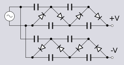
The most common type of voltage multiplier is the half-wave series multiplier, also called the Villard cascade (but actually invented by Heinrich Greinacher
Heinrich Greinacher
Heinrich Greinacher was a Swiss physicist. He is regarded as an original experimenter and is the developer of the magnetron and the Greinacher multiplier....
).
Operation
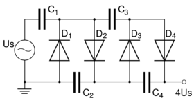
Assuming that the peak voltage of the AC source is +Us we can describe the (simplified) working of the cascade as follows: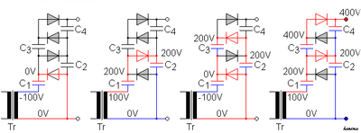
- negative peak (−Us): The C1 capacitor is charged through diode D1 to Us VVoltThe volt is the SI derived unit for electric potential, electric potential difference, and electromotive force. The volt is named in honor of the Italian physicist Alessandro Volta , who invented the voltaic pile, possibly the first chemical battery.- Definition :A single volt is defined as the...
(potential difference between left and right plate of the capacitor is Us) - positive peak (+Us): the potential of C1 adds with that of the source, thus charging C2 to 2Us through D2
- negative peak: potential of C1 drops to 0 V thus allowing C3 to be charged through D3 to 2Us.
- positive peak: potential of C1 rises to 2Us (analogously to step 2), also charging C4 to 2Us. The output voltage (the sum of voltages under C2 and C4) raises till 4Us.
In reality more cycles are required for C4 to reach the full voltage. Each additional stage of two diodes and two capacitors increases the output voltage by twice the peak AC supply voltage.
Voltage doubler and tripler
A voltage doubler uses two stages to approximately double the DC voltage that would have been obtained from a single-stage rectifier. An example of a voltage doubler is found in the input stage of switch mode power supplies containing a slide switch to select either 120 volt or 240 volt supply. In the 120 volt position the input is configured as a voltage doubler, so that the rest of the circuit sees approximately the same voltage independent of the supply voltage applied.A voltage tripler is a three-stage voltage multiplier. A tripler is a popular type of voltage multiplier. The output voltage of a tripler is in practice below three times the peak input voltage due to their high impedance
Electrical impedance
Electrical impedance, or simply impedance, is the measure of the opposition that an electrical circuit presents to the passage of a current when a voltage is applied. In quantitative terms, it is the complex ratio of the voltage to the current in an alternating current circuit...
, caused in part by the fact that as each capacitor
Capacitor
A capacitor is a passive two-terminal electrical component used to store energy in an electric field. The forms of practical capacitors vary widely, but all contain at least two electrical conductors separated by a dielectric ; for example, one common construction consists of metal foils separated...
in the chain supplies power to the next, it partially discharges, losing voltage doing so.
Triplers were commonly used in color television receivers to provide the high voltage for the cathode ray tube (picture tube). TV triplers became known for their susceptibility to dampness. Even short exposures to humid air caused many failures. Many 1970s TV sets used open triplers, and the individual diode sticks could be replaced if they failed.
Triplers are still used in high voltage
High voltage
The term high voltage characterizes electrical circuits in which the voltage used is the cause of particular safety concerns and insulation requirements...
supplies such as copiers, laser printer
Laser printer
A laser printer is a common type of computer printer that rapidly produces high quality text and graphics on plain paper. As with digital photocopiers and multifunction printers , laser printers employ a xerographic printing process, but differ from analog photocopiers in that the image is produced...
s, insect electrocutors.
Breakdown voltage
While the multiplier can be used to produce thousands of volts of output, the individual components do not need to be rated to withstand the entire voltage range. Each component only needs to be concerned with the relative voltage differences directly across its own terminals and of the components immediately adjacent to it.Typically a voltage multiplier will be physically arranged like a ladder, so that the progressively increasing voltage potential is not given the opportunity to arc across to the much lower potential sections of the circuit.
Note that some safety margin is needed across the relative range of voltage differences in the multiplier, so that the ladder can survive the shorted failure of at least one diode or capacitor component. Otherwise a single-point shorting failure could successively over-voltage and destroy each next component in the multiplier, potentially destroying the entire multiplier chain.
Other circuit topologies
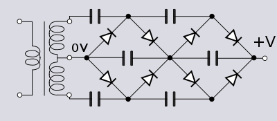
Stacking:
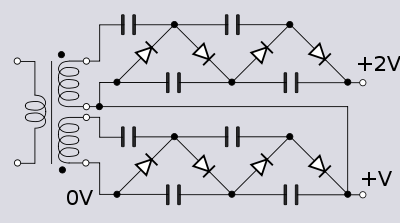
An even number of diode-capacitor cells is used in any column so that the cascade ends on a smoothing cell. If it were odd and ended on a clamping cell the ripple voltage would be very large. Larger capacitors in the connecting column also reduce ripple but at the expense of charging time and increased diode current.
Dickson charge pump
The Dickson charge pump, or Dickson multiplier, is a modification of the Greinacher/Cockcroft-Walton multiplier. Unlike that circuit, however, the Dickson multiplier takes a DC supply as its input so is a form of DC-to-DC converter. Also unlike Greinacher/Cockcroft-Walton which is used on high-voltage applications, the Dickson multiplier is intended for low-voltage purposes. In addition to the DC input, the circuit requires a feed of two clock pulse trains with an amplitude swinging between the DC supply rails. These two pulse trains are opposite phases to each other and non-overlapping so that the switching behaviour is break-before-make.To describe the ideal operation of the circuit, number the diodes D1, D2 etc. from left to right and the capacitors C1, C2 etc. When the clock
 is low, D1 will charge C1 to Vin. When
  goes high the top plate of C1 is pushed up to 2Vin. D1 is then turned off and D2 turned on and C2 begins to charge to 2Vin. On the next clock cycle
  again goes low and now
  goes high pushing the top plate of C2 to 3Vin. D2 switches off and D3 switches on, charging C3 to 3Vin and so on with charge passing up the chain, hence the name charge pump
Charge pump
A charge pump is a kind of DC to DC converter that uses capacitors as energy storage elements to create either a higher or lower voltage power source. Charge pump circuits are capable of high efficiencies, sometimes as high as 90–95% while being electrically simple circuits.Charge pumps use some...
. The final diode-capacitor cell in the cascade is connected to ground rather than a clock phase and hence is not a multiplier; it is a peak detector
Envelope detector
An envelope detector is an electronic circuit that takes a high-frequency signal as input and provides an output which is the "envelope" of the original signal. The capacitor in the circuit stores up charge on the rising edge, and releases it slowly through the resistor when the signal falls...
which merely provides smoothing.
There are a number of factors which reduce the output from the ideal case of nVin. One of these is the threshold voltage, VT of the switching device, that is, the voltage required to turn it on. The output will be reduced by at least nVT due to the volt drops across the switches. Schottky diode
Schottky diode
The Schottky diode is a semiconductor diode with a low forward voltage drop and a very fast switching action...
s are commonly used in Dickson multipliers for their low forward voltage drop, amongst other reasons. Another difficulty is that there are parasitic capacitance
Parasitic capacitance
In electrical circuits, parasitic capacitance, stray capacitance or, when relevant, self-capacitance , is an unavoidable and usually unwanted capacitance that exists between the parts of an electronic component or circuit simply because of their proximity to each other...
s to ground at each node. These parasitic capacitances act as voltage dividers with the circuit's storage capacitors reducing the output voltage still further. Up to a point, a higher clock frequency is beneficial: the ripple is reduced and the high frequency makes the remaining ripple easier to filter. Also the size of capacitors needed is reduced since less charge needs to be stored per cycle. However, losses through stray capacitance increase with increasing clock frequency and a practical limit is around a few hundred kilohertz.
Dickson multipliers are frequently found in integrated circuit
Integrated circuit
An integrated circuit or monolithic integrated circuit is an electronic circuit manufactured by the patterned diffusion of trace elements into the surface of a thin substrate of semiconductor material...
s (ICs) where they are used to increase a low-voltage battery supply to the voltage needed by the IC. It is advantageous to the IC designer and manufacturer to be able to use the same technology and the same basic device throughout the IC. For this reason, in the popular CMOS
CMOS
Complementary metal–oxide–semiconductor is a technology for constructing integrated circuits. CMOS technology is used in microprocessors, microcontrollers, static RAM, and other digital logic circuits...
technology ICs the transistor which forms the basic building block of circuits is the MOSFET
MOSFET
The metal–oxide–semiconductor field-effect transistor is a transistor used for amplifying or switching electronic signals. The basic principle of this kind of transistor was first patented by Julius Edgar Lilienfeld in 1925...
. Consequently, the diodes in the Dickson multiplier are often replaced with MOSFETs wired to behave as diodes.
The diode-wired MOSFET version of the Dickson multiplier does not work very well at very low voltages because of the large drain-source volt drops of the MOSFETs. Frequently, a more complex circuit is used to overcome this problem. One solution is to connect in parallel with the switching MOSFET another MOSFET biased into its linear region. This second MOSFET has a lower drain-source voltage than the switching MOSFET would have on its own (because the switching MOSFET is driven hard on) and consequently the output voltage is increased. The gate of the linear biased MOSFET is connected to the output of the next stage so that it is turned off while the next stage is charging from the previous stage's capacitor. That is, the linear-biased transistor is turned off at the same time as the switching transistor.
An ideal 4-stage Dickson multiplier (x5 multiplier) with an input of would have an output of . However, a diode-wired MOSFET 4-stage multiplier might only have an output of . Adding parallel MOSFETs in the linear region improves this to around . More complex circuits still can achieve an output much closer to the ideal case.
Many other variations and improvements to the basic Dickson circuit exist. Some attempt to reduce the switching threshold voltage such as the Mandal-Sarpeshkar multiplier or the Wu multiplier. Other circuits cancel out the threshold voltage: the Umeda multiplier does it with an externally provided voltage and the Nakamoto multiplier with internally generated voltage. The Bergeret multiplier concentrates on maximising power efficiency.
Dickson charge pump modified for RF
In CMOS integrated circuits clock signals are readily available, or else easily generated. This is not always the case in RFRadio frequency
Radio frequency is a rate of oscillation in the range of about 3 kHz to 300 GHz, which corresponds to the frequency of radio waves, and the alternating currents which carry radio signals...
integrated circuits, but often a source of RF power will be available. The standard Dickson multiplier circuit can be modified to meet this requirement by simply grounding the normal input and one of the clock inputs. RF power is injected into the other clock input, which then becomes the circuit input. The RF signal is effectively the clock as well as the source of power. However, since the clock is injected only into every other node the circuit only achieves a stage of multiplication for every second diode-capacitor cell. The other diode-capacitor cells are merely acting as peak detectors and smoothing the ripple without increasing the multiplication.
Cross-coupled switched capacitor
A voltage multiplier may be formed of a cascade of voltage doublers of the cross-coupled switched capacitor type. This type of circuit is typically used instead of a Dickson multiplier when the source voltage is or less. Dickson multipliers have increasingly poor power conversion efficiency as the input voltage drops because the voltage drop across the diode-wired transistors becomes much more significant compared to the output voltage. Since the transistors in the cross-coupled circuit are not diode-wired the volt-drop problem is not so serious.The circuit works by alternately switching the output of each stage between a voltage doubler driven by
 and one driven by
  . This behaviour leads to another advantage over the Dickson multiplier; reduced ripple voltage at double the frequency. The increase in ripple frequency is advantageous because it is easier to remove by filtering. Each stage (in an ideal circuit) raises the output voltage by the peak clock voltage. Assuming that this is the same level as the DC input voltage then an n stage multiplier will (ideally) output nVin. The chief cause of losses in the cross-coupled circuit is parasitic capacitance rather than switching threshold voltage. This causes losses because some of the energy has to go into charging up the stray capacitances on each cycle.
Applications
The high-voltage supplies for cathode ray tubeCathode ray tube
The cathode ray tube is a vacuum tube containing an electron gun and a fluorescent screen used to view images. It has a means to accelerate and deflect the electron beam onto the fluorescent screen to create the images. The image may represent electrical waveforms , pictures , radar targets and...
s often use voltage multipliers with the final-stage smoothing capacitor formed by the interior and exterior aquadag
Aquadag
Aquadag is a trade name for a graphite based coating commonly found in cathode ray tubes. It is manufactured by Acheson Industries, a subsidiary of ICI. The name is a shortened form of "Aqueous Deflocculated Acheson Graphite". Other related products include Oildag, Electrodag and Molydag. The...
coatings on the CRT itself.
A common type of voltage multiplier used in high-energy physics is the Cockcroft–Walton generator (which was designed by John Douglas Cockcroft and Ernest Thomas Sinton Walton for a particle accelerator
Particle accelerator
A particle accelerator is a device that uses electromagnetic fields to propel charged particles to high speeds and to contain them in well-defined beams. An ordinary CRT television set is a simple form of accelerator. There are two basic types: electrostatic and oscillating field accelerators.In...
, for use in research that won them the Nobel Prize in Physics
Nobel Prize in Physics
The Nobel Prize in Physics is awarded once a year by the Royal Swedish Academy of Sciences. It is one of the five Nobel Prizes established by the will of Alfred Nobel in 1895 and awarded since 1901; the others are the Nobel Prize in Chemistry, Nobel Prize in Literature, Nobel Peace Prize, and...
in 1951).
See also
- Marx generatorMarx generatorA Marx generator is an electrical circuit first described by Erwin Otto Marx in 1924. Its purpose is to generate a high-voltage pulse. Marx generators are often used to simulate the effects of lightning on power line gear and aviation equipment....
(a device that uses spark gapSpark gapA spark gap consists of an arrangement of two conducting electrodes separated by a gap usually filled with a gas such as air, designed to allow an electric spark to pass between the conductors. When the voltage difference between the conductors exceeds the gap's breakdown voltage, a spark forms,...
s instead of diodes as the switching elements and can deliver higher peak currents than diodes can) - RectifierRectifierA rectifier is an electrical device that converts alternating current , which periodically reverses direction, to direct current , which flows in only one direction. The process is known as rectification...
- Voltage doublerVoltage doublerA voltage doubler is an electronic circuit which charges capacitors from the input voltage and switches these charges in such a way that, in the ideal case, exactly twice the voltage is produced at the output as at its input....
- Voltage tripler
External links
- Basic multiplier circuits
- Cockcroft Walton multipliers
- Schematic of Kadette brand (International Radio Corp.) model 1019. A 1937 radioRadioRadio is the transmission of signals through free space by modulation of electromagnetic waves with frequencies below those of visible light. Electromagnetic radiation travels by means of oscillating electromagnetic fields that pass through the air and the vacuum of space...
with a vacuum tubeVacuum tubeIn electronics, a vacuum tube, electron tube , or thermionic valve , reduced to simply "tube" or "valve" in everyday parlance, is a device that relies on the flow of electric current through a vacuum...
(25Z5) voltage multiplier rectifier.