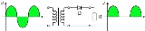
Encyclopedia
A
rectifier is an
electrical device, comprising one or more
semiconductive devices or
vacuum tubes arranged for converting
alternating current to
direct current. When just one diode is used to rectify AC the difference between the term
diode and the term
rectifier is merely one of usage, e.g., the term
rectifier describes a
diode that is being used to convert AC to DC.
Rectification is a process whereby
alternating current is converted into
direct current . Almost all rectifiers comprise a number of diodes in a specific arrangement for more efficiently converting AC to DC than is possible with just a single diode. Rectification is commonly performed by semiconductor
diodes. Before the development of solid state rectifiers,
vacuum tube diodes and copper oxide or selenium rectifier stacks were used. Early radios, called
crystal sets, used a "cat's whisker" of fine wire pressing on a crystal of
galena to serve as a point contact rectifier or "crystal detector". In gas heating systems "flame rectification" can be used to detect a flame. Two metal electrodes in the outer layer of the flame provide a current path and rectification of an applied alternating voltage, but only while the flame is present.
Half-wave rectification
A half wave rectifier is a special case of a
clipper. In half wave rectification, either the positive or negative half of the AC wave is passed easily while the other half is blocked, depending on the polarity of the rectifier. Because only one half of the input waveform reaches the output, it is very inefficient if used for power transfer. Half wave rectification can be achieved with a single diode in a one phase supply.
Full-wave rectification
Full-wave rectification converts both polarities of the input waveform to DC, and is more efficient. However, in a circuit with a non-center tapped transformer, four rectifiers are required instead of the one needed for half-wave rectification. This is due to each output polarity requiring 2 rectifiers each, for example, one for when AC terminal 'X' is positive and one for when AC terminal 'Y' is positive. The other DC output requires exactly the same, resulting in four individual junctions . Four rectifiers arranged this way are called a
bridge rectifier:
A full wave rectifier converts the whole of the input waveform to one of constant polarity at its output by reversing the negative portions of the alternating current waveform. The positive portions thus combine with the reversed negative portions to produce an entirely positive voltage/current waveform.
For single phase AC, if the AC is center-tapped, then two diodes back-to-back form a full wave rectifier.
A very common
vacuum tube rectifier configuration contained one cathode and twin anodes inside a single envelope; in this way, the two diodes required only one vacuum tube. The 5U4 and 5Y3 were popular examples of this configuration.
For three phase AC, six diodes are used. Typically there are three pairs of diodes, each pair, though, is not the same kind of
double diode that would be used for a full wave single phase rectifier. Instead the pairs are in series . Typically, commercially available double diodes have four terminals so the user can configure them as single phase split supply use, for half a bridge, or for three phase use.
Most devices that generate alternating current generate three phase AC. For example, an automobile alternator has six diodes inside it to function as a full wave rectifier for battery charge applications.
Peak loss
An aspect of most rectification is a loss from peak input voltage to the peak output voltage, caused by the threshold voltage of the diodes . Half wave rectification and full wave rectification using two separate secondaries will have a peak voltage loss of one diode drop. Bridge rectifcation will have a loss of two diode drops. This may represent significant power loss in very low voltage supplies. In addition, the diodes will not conduct below this voltage, so the circuit is only passing current through for a portion of each half-cycle, causing short segments of zero voltage to appear between each "hump".
Rectifier output smoothing
While half- and full-wave rectification suffices to deliver a
form of DC output, neither produces constant voltage DC. In order to produce
steady DC from a rectified AC supply, a
smoothing circuit is required. In its simplest form this can be what is known as a
reservoir capacitor or smoothing capacitor, placed at the DC output of the rectifier. There will still remain an amount of AC ripple voltage where the voltage is not completely smoothed.
Sizing of the capacitor represents a tradeoff. For a given load, a larger capacitor will reduce ripple but will cost more and will create higher peak currents in the transformer secondry and in the supply feeding it. In extreme cases where many rectifiers are loaded onto a power distribution circuit, it may prove difficult for the power distribution authority to maintain a correctly shaped sinusoidal voltage curve.
To further reduce this ripple, a
capacitor-input filter can be used. This complements the reservoir capacitor with a choke and a second filter capacitor, so that a steadier DC output can be obtained across the terminals of the filter capacitor. The choke presents a high impedance to the ripple current.
If the DC load is very demanding of a smooth supply voltage, a voltage regulator will be used either in addition to the capacitor-input filter, both to remove the last of the ripple and to deal with variations in supply and load characteristics.
Applications
The primary application of rectifiers is to derive usable DC power from an AC supply. Virtually all electronics requires a DC supply but mains power is AC so rectifiers find uses inside the power supplies of virtually all electronic equipment.
Converting DC voltage from one level to another is much more complicated but rectifiers are usually involved. One method of such DC-to-DC conversion is to first convert to AC , then use a transformer to change the voltage, and finally rectify it back to DC.
Rectifiers also find a use in detection of
amplitude modulated radio signals. The signal may or may not be amplified before detection but if unamplified a very low voltage drop diode must be used. In this case the capacitor and load resistance must be carefully matched. Too low a capacitance will result in the high frequency carrier passing to the output and too high will result in the capacitor just charging and staying charged.
High power rectification
Vacuum tubes, metal oxide rectifier stacks and semiconductor diodes are useful in the range of milliamperes to a few hundred amperes of current. In order to handle thousands of amperes at hundreds of volts or hundreds of amperes at thousands of volts, some interesting solutions have been devised. For example, to convert AC current into DC current in
electric locomotives, a
synchronous rectifier may be used. It consists of a synchronous motor driving a set of heavy-duty electrical contacts. The motor spins in time with the AC frequency and periodically reverses the connections to the load just when the sinusoidal current goes through a zero-crossing. The contacts do not have to
switch a large current, but they need to be able to
carry a large current to supply the locomotive's DC traction motors. In recent years semiconductor synchronous rectifiers have been designed, although they still cannot compete with the low losses offered by the older electromechanical synchronous rectifiers.
Another type of rectifier used in high voltage power transmission systems and industrial processing since about 1909 is a
mercury arc rectifier or
mercury arc valve. The device is enclosed in a bulbous glass vessel or large metal tub. One electrode, the
cathode, is submerged in a pool of liquid mercury at the bottom of the vessel and one or more high purity graphite electrodes, called
anodes, are suspended above the pool. There may be several auxiliary electrodes to aid in starting and maintaining the arc. When an electric arc is established between the cathode pool and suspended anodes, a stream of electrons flows from the cathode to the anodes through the ionized mercury, but not the other way. These devices can be used at power levels of hundreds of kilowatts, and may be built to handle one to six phases of AC current. Mercury arc rectifiers have largely been replaced by silicon semiconductor rectifiers from the mid 1970s onward.
A third type of rectifier, a
motor-generator set, is not a rectifier in the strict sense. Here, an AC motor is mechanically coupled to a DC
generator. The DC generator produces a multiphase alternating current in its windings, but a commutator is used to convert the alternating currents into a direct current output. Such devices are useful for producing hundreds of amperes of direct current at tens to hundreds of volts.
Patents
— Copper oxide rectifiers
See also