
Vacuum tube
Overview
Electronics
Electronics is the branch of science, engineering and technology that deals with electrical circuits involving active electrical components such as vacuum tubes, transistors, diodes and integrated circuits, and associated passive interconnection technologies...
, a vacuum tube, electron tube (in North America), or thermionic valve (elsewhere, especially in Britain), reduced to simply "tube" or "valve" in everyday parlance, is a device that relies on the flow of electric current through a vacuum. Vacuum tubes may be used for rectification
Rectifier
A rectifier is an electrical device that converts alternating current , which periodically reverses direction, to direct current , which flows in only one direction. The process is known as rectification...
, amplification
Amplifier
Generally, an amplifier or simply amp, is a device for increasing the power of a signal.In popular use, the term usually describes an electronic amplifier, in which the input "signal" is usually a voltage or a current. In audio applications, amplifiers drive the loudspeakers used in PA systems to...
, switch
Switch
In electronics, a switch is an electrical component that can break an electrical circuit, interrupting the current or diverting it from one conductor to another....
ing, or similar processing or creation of electrical signals.
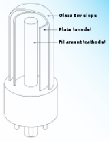
Vacuum tubes rely on thermionic emission
Thermionic emission
Thermionic emission is the heat-induced flow of charge carriers from a surface or over a potential-energy barrier. This occurs because the thermal energy given to the carrier overcomes the binding potential, also known as work function of the metal. The charge carriers can be electrons or ions, and...
of electrons from a hot filament
Hot cathode
In vacuum tubes, a hot cathode is a cathode electrode which emits electrons due to thermionic emission. In the accelerator community, these are referred to as thermionic cathodes. The heating element is usually an electrical filament...
or cathode
Hot cathode
In vacuum tubes, a hot cathode is a cathode electrode which emits electrons due to thermionic emission. In the accelerator community, these are referred to as thermionic cathodes. The heating element is usually an electrical filament...
, that then travel through a vacuum toward the anode
Anode
An anode is an electrode through which electric current flows into a polarized electrical device. Mnemonic: ACID ....
(commonly called the plate), which is held at a positive voltage relative to the cathode.
Unanswered Questions
Discussions