

Distributed element model
Encyclopedia
- This article is an example from the domain of electrical systems, which is a special case of the more general distributed parameter systems.
In electrical engineering
Electrical engineering
Electrical engineering is a field of engineering that generally deals with the study and application of electricity, electronics and electromagnetism. The field first became an identifiable occupation in the late nineteenth century after commercialization of the electric telegraph and electrical...
, the distributed element model or transmission line model of electrical circuit
Electrical network
An electrical network is an interconnection of electrical elements such as resistors, inductors, capacitors, transmission lines, voltage sources, current sources and switches. An electrical circuit is a special type of network, one that has a closed loop giving a return path for the current...
s assumes that the attributes of the circuit (resistance
Electrical resistance
The electrical resistance of an electrical element is the opposition to the passage of an electric current through that element; the inverse quantity is electrical conductance, the ease at which an electric current passes. Electrical resistance shares some conceptual parallels with the mechanical...
, capacitance
Capacitance
In electromagnetism and electronics, capacitance is the ability of a capacitor to store energy in an electric field. Capacitance is also a measure of the amount of electric potential energy stored for a given electric potential. A common form of energy storage device is a parallel-plate capacitor...
, and inductance
Inductance
In electromagnetism and electronics, inductance is the ability of an inductor to store energy in a magnetic field. Inductors generate an opposing voltage proportional to the rate of change in current in a circuit...
) are distributed continuously throughout the material of the circuit. This is in contrast to the more common lumped element model
Lumped element model
The lumped element model simplifies the description of the behaviour of spatially distributed physical systems into a topology consisting of discrete entities that approximate the behaviour of the distributed system under certain assumptions...
, which assumes that these values are lumped into electrical components that are joined by perfectly conducting wires. In the distributed element model, each circuit element is infinitesimally small, and the wire
Wire
A wire is a single, usually cylindrical, flexible strand or rod of metal. Wires are used to bear mechanical loads and to carry electricity and telecommunications signals. Wire is commonly formed by drawing the metal through a hole in a die or draw plate. Standard sizes are determined by various...
s connecting elements are not assumed to be perfect conductors; that is, they have impedance. Unlike the lumped element model, it assumes non-uniform current along each branch and non-uniform voltage along each node. The distributed model is used at high frequencies
Frequency
Frequency is the number of occurrences of a repeating event per unit time. It is also referred to as temporal frequency.The period is the duration of one cycle in a repeating event, so the period is the reciprocal of the frequency...
where the wavelength
Wavelength
In physics, the wavelength of a sinusoidal wave is the spatial period of the wave—the distance over which the wave's shape repeats.It is usually determined by considering the distance between consecutive corresponding points of the same phase, such as crests, troughs, or zero crossings, and is a...
approaches the physical dimensions of the circuit, making the lumped model inaccurate.
Applications
The distributed element model is more accurate but more complex than the lumped element modelLumped element model
The lumped element model simplifies the description of the behaviour of spatially distributed physical systems into a topology consisting of discrete entities that approximate the behaviour of the distributed system under certain assumptions...
. The use of infinitesimals will often require the application of calculus
Calculus
Calculus is a branch of mathematics focused on limits, functions, derivatives, integrals, and infinite series. This subject constitutes a major part of modern mathematics education. It has two major branches, differential calculus and integral calculus, which are related by the fundamental theorem...
whereas circuits analysed by the lumped element model can be solved with linear algebra
Linear algebra
Linear algebra is a branch of mathematics that studies vector spaces, also called linear spaces, along with linear functions that input one vector and output another. Such functions are called linear maps and can be represented by matrices if a basis is given. Thus matrix theory is often...
. The distributed model is consequently only usually applied when accuracy calls for its use. Where this point is depends on the accuracy required in a specific application, but essentially, it needs to be used in circuits where the wavelengths of the signals have become comparable to the physical dimensions of the components. An often quoted engineering rule of thumb (not to be taken too literally because there are many exceptions) is that parts larger than one tenth of a wavelength will usually need to be analysed as distributed elements.
Transmission lines
Transmission lineTransmission line
In communications and electronic engineering, a transmission line is a specialized cable designed to carry alternating current of radio frequency, that is, currents with a frequency high enough that its wave nature must be taken into account...
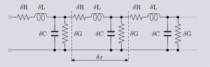
s are a common example of the use of the distributed model. Its use is dictated because the length of the line will usually be many wavelengths of the circuit's operating frequency. Even for the low frequencies used on power transmission lines, one tenth of a wavelength is still only about 500 kilometres at 60 Hz. Transmission lines are usually represented in terms of the primary line constants
Primary line constants
The primary line constants are parameters that describe the characteristics of copper transmission lines in terms of the physical electrical properties of the line. The primary line constants are only relevant to copper lines and are to be contrasted with the secondary line constants, which can...
as shown in figure 1. From this model the behaviour of the circuit is described by the secondary line constants which can be calculated from the primary ones.
The primary line constants are normally taken to be constant with position along the line leading to a particularly simple analysis and model. However, this is not always the case, variations in physical dimensions along the line will cause variations in the primary constants, that is, they have now to be described as functions of distance. Most often, such a situation represents an unwanted deviation from the ideal, such as a manufacturing error, however, there are a number of components where such longitudinal variations are deliberately introduced as part of the function of the component. A well known example of this is the horn antenna
Horn (telecommunications)
A horn antenna or microwave horn is an antenna that consists of a flaring metal waveguide shaped like a horn to direct the radio waves. Horns are widely used as antennas at UHF and microwave frequencies, above 300 MHz...
.
Where reflection
Signal reflection
Signal reflection occurs when a signal is transmitted along a transmission medium, such as a copper cable or an optical fiber, some of the signal power may be reflected back to its origin rather than being carried all the way along the cable to the far end. This happens because imperfections in the...
s are present on the line, quite short lengths of line can exhibit effects
Reflections of signals on conducting lines
A signal travelling along an electrical transmission line will be partly, or wholly, reflected back in the opposite direction when the travelling signal encounters a discontinuity in the transmission parameters of the line, or at the far end of the line if the line is not correctly terminated in...
that are simply not predicted by the lumped element model. A quarter wavelength line, for instance, will transform
Quarter wave impedance transformer
A quarter-wave impedance transformer, often written as λ/4 impedance transformer, is a component used in electrical engineering consisting of a length of transmission line or waveguide exactly one-quarter of a wavelength long and terminated in some known impedance. The device presents at its...
the terminating impedance
Electrical impedance
Electrical impedance, or simply impedance, is the measure of the opposition that an electrical circuit presents to the passage of a current when a voltage is applied. In quantitative terms, it is the complex ratio of the voltage to the current in an alternating current circuit...
into its dual. This can be a wildly different impedance.
High frequency transistors
Bipolar junction transistor
|- align = "center"| || PNP|- align = "center"| || NPNA bipolar transistor is a three-terminal electronic device constructed of doped semiconductor material and may be used in amplifying or switching applications. Bipolar transistors are so named because their operation involves both electrons...
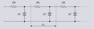
at high frequencies. The analysis of charge carrier
Charge carrier
In physics, a charge carrier is a free particle carrying an electric charge, especially the particles that carry electric currents in electrical conductors. Examples are electrons and ions...
s crossing the base region is not accurate when the base region is simply treated as a lumped element. A more successful model is a simplified transmission line model which includes distributed bulk resistance of the base material and distributed capacitance to the substrate. This model is represented in figure 2.
Resistivity measurements
In many situations it is desired to measure resistivityResistivity
Electrical resistivity is a measure of how strongly a material opposes the flow of electric current. A low resistivity indicates a material that readily allows the movement of electric charge. The SI unit of electrical resistivity is the ohm metre...
of a bulk material by applying an electrode array
Electrode array
An electrode array is a configuration of electrodes used for measuring either an electric current or voltage. Some electrode arrays can operate in a bidirectional fashion, in that they can also be used to provide a stimulating pattern of electric current or voltage.Common arrays...
at the surface. Amongst the fields that use this technique are geophysics
Geophysics
Geophysics is the physics of the Earth and its environment in space; also the study of the Earth using quantitative physical methods. The term geophysics sometimes refers only to the geological applications: Earth's shape; its gravitational and magnetic fields; its internal structure and...
(because it avoids having to dig into the substrate) and the semiconductor industry also use it (for the similar reason that it is non-intrusive) for testing bulk silicon wafers. The basic arrangement is shown in figure 3, although normally more electrodes would be used. To form a relationship between the voltage and current measured on the one hand, and the resistivity of the material on the other, it is necessary to apply the distributed element model by considering the material to be an array of infinitesimal resistor elements. Unlike the transmission line example, the need to apply the distributed element model arises from the geometry of the setup, and not from any wave propagation considerations.
The model used here needs to be truly 3-dimensional (transmission line models are usually described by elements of a one-dimensional line). It is also possible that the resistances of the elements will be functions of the co-ordinates, indeed, in the geophysical application it may well be that regions of changed resistivity are the very things that it is desired to detect.
Inductor windings
Another example where a simple one-dimensional model will not suffice is the windings of an inductor. Coils of wire have capacitance between adjacent turns (and also more remote turns as well, but the effect progressively diminishes). For a single layer solenoid, the distributed capacitance will mostly lie between adjacent turns as shown in figure 4 between turns T1 and T2, but for multiple layer windings and more accurate models distributed capacitance to other turns must also be considered. This model is fairly difficult to deal with in simple calculations and for the most part is avoided. The most common approach is to roll up all the distributed capacitance into one lumped element in parallel with the inductance and resistance of the coil. This lumped model works successfully at low frequencies but falls apart at high frequencies where the usual practice is to simply measure (or specify) an overall QQ factor
In physics and engineering the quality factor or Q factor is a dimensionless parameter that describes how under-damped an oscillator or resonator is, or equivalently, characterizes a resonator's bandwidth relative to its center frequency....
for the inductor without associating a specific equivalent circuit.