
Transmission line
Encyclopedia
In communications and electronic engineering
, a transmission line is a specialized cable designed to carry alternating current
of radio frequency
, that is, currents with a frequency
high enough that its wave
nature must be taken into account. Transmission lines are used for purposes such as connecting radio transmitters
and receivers with their antennas
, distributing cable television
signals, and computer network connections.
range or higher, which reverse direction millions to billions of times per second, because the energy tends to radiate off the cable as radio wave
s, causing power losses. Radio frequency currents also tend to reflect from discontinuities in the cable such as connectors
, and travel back down the cable toward the source. These reflections act as bottlenecks, preventing the power from reaching the destination. Transmission lines use specialized construction such as precise conductor dimensions and spacing, and impedance matching
, to carry electromagnetic signals with minimal reflections and power losses. Types of transmission line include ladder line, coaxial cable
, dielectric slabs, stripline
, optical fiber
, and waveguide
s. The higher the frequency, the shorter are the waves in a transmission medium. Transmission lines must be used when the frequency is high enough that the wavelength
of the waves begins to approach the length of the cable used. To conduct energy at frequencies above the radio range, such as millimeter waves, infrared
, and light
, the waves become much smaller than the dimensions of the structures used to guide them, so transmission line techniques become inadequate and the methods of optics
are used.
The theory of sound wave propagation is very similar mathematically to that of electromagnetic waves, so techniques from transmission line theory are also used to build structures to conduct acoustic waves; and these are also called transmission lines.
, Lord Kelvin and Oliver Heaviside
. In 1855 Lord Kelvin formulated a diffusion model of the current in a submarine cable. The model correctly predicted the poor performance of the 1858 trans-Atlantic submarine telegraph cable
. In 1885 Heaviside published the first papers that described his analysis of propagation in cables and the modern form of the telegrapher's equations.
with corresponding wavelength
s comparable to or less than the length of the wire.
A common rule of thumb is that the cable or wire should be treated as a transmission line if the length is greater than 1/10 of the wavelength. At this length the phase delay and the interference of any reflections on the line become important and can lead to unpredictable behavior in systems which have not been carefully designed using transmission line theory.
 For the purposes of analysis, an electrical transmission line can be modelled as a two-port network
(also called a quadrupole network), as follows:
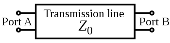
In the simplest case, the network is assumed to be linear (i.e. the complex
voltage across either port is proportional to the complex current flowing into it when there are no reflections), and the two ports are assumed to be interchangeable. If the transmission line is uniform along its length, then its behaviour is largely described by a single parameter called the characteristic impedance
, symbol Z0. This is the ratio of the complex voltage of a given wave to the complex current of the same wave at any point on the line. Typical values of Z0 are 50 or 75 ohms for a coaxial cable
, about 100 ohms for a twisted pair of wires, and about 300 ohms for a common type of untwisted pair used in radio transmission.
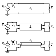
When sending power down a transmission line, it is usually desirable that as much power as possible will be absorbed by the load and as little as possible will be reflected back to the source. This can be ensured by making the load impedance equal to Z0, in which case the transmission line is said to be matched
.
Some of the power that is fed into a transmission line is lost because of its resistance. This effect is called ohmic or resistive loss (see ohmic heating). At high frequencies, another effect called dielectric loss becomes significant, adding to the losses caused by resistance. Dielectric loss is caused when the insulating material inside the transmission line absorbs energy from the alternating electric field and converts it to heat
(see dielectric heating
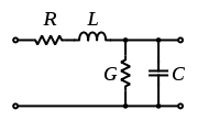
). The Transmission Line is modeled with a Resistance(R) and Inductance(L) in Series with a Capacitance(C) and Conductance(G) in Parallel. The Resistance and Conductance contributes to the loss of the Transmission Line.
The total loss of power in a transmission line is often specified in decibels per metre
(dB/m), and usually depends on the frequency of the signal. The manufacturer often supplies a chart showing the loss in dB/m at a range of frequencies. A loss of 3 dB corresponds approximately to a halving of the power.
High-frequency transmission lines can be defined as those designed to carry electromagnetic waves whose wavelength
s are shorter than or comparable to the length of the line. Under these conditions, the approximations useful for calculations at lower frequencies are no longer accurate. This often occurs with radio
, microwave
and optical
signals, metal mesh optical filters
, and with the signals found in high-speed digital circuit
s.
and current
on an electrical transmission line with distance and time. They were developed by Oliver Heaviside
who created the transmission line model, and are based on Maxwell's Equations
.
 The transmission line model represents the transmission line as an infinite series of two-port elementary components, each representing an infinitesimally short segment of the transmission line:
The model consists of an infinite series of the elements shown in the figure, and that the values of the components are specified per unit length so the picture of the component can be misleading. ,
,  ,
,  , and
, and  may also be functions of frequency. An alternative notation is to use
  ,
,  ,
,  and
and  to emphasize that the values are derivatives with respect to length. These quantities can also be known as the primary line constants
to distinguish from the secondary line constants derived from them, these being the propagation constant
, attenuation constant and phase constant.
The line voltage and the current
  can be expressed in the frequency domain as
When the elements and
and  are negligibly small the transmission line is considered as a lossless structure. In this hypothetical case, the model depends only on the
  and
and  elements which greatly simplifies the analysis. For a lossless transmission line, the second order steady-state Telegrapher's equations are:

These are wave equation
s which have plane wave
s with equal propagation speed in the forward and reverse directions as solutions. The physical significance of this is that electromagnetic waves propagate down transmission lines and in general, there is a reflected component that interferes with the original signal. These equations are fundamental to transmission line theory.
If and
and  are not neglected, the Telegrapher's equations become:

where

and the characteristic impedance is:
The solutions for and
and  are:
are:


The constants and
and  must be determined from boundary conditions. For a voltage pulse
  , starting at
  and moving in the positive
  -direction, then the transmitted pulse
  at position
  can be obtained by computing the Fourier Transform,
  , of
, of  , attenuating each frequency component by
  , advancing its phase by
  , and taking the inverse Fourier Transform. The real and imaginary parts of
  can be computed as


where atan2
is the two-parameter arctangent, and

For small losses and high frequencies, to first order in and
and  one obtains

Noting that an advance in phase by is equivalent to a time delay by
  ,
,  can be simply computed as
 of a transmission line is the ratio of the amplitude of a single voltage wave to its current wave. Since most transmission lines also have a reflected wave, the characteristic impedance is generally not the impedance that is measured on the line.
For a lossless transmission line, it can be shown that the impedance measured at a given position from the load impedance
  is
is
where is the wavenumber
.
In calculating , the wavelength is generally different inside the transmission line to what it would be in free-space and the velocity constant of the material the transmission line is made of needs to be taken into account when doing such a calculation.
 where n is an integer (meaning that the length of the line is a multiple of half a wavelength), the expression reduces to the load impedance so that

for all . This includes the case when
  , meaning that the length of the transmission line is negligibly small compared to the wavelength. The physical significance of this is that the transmission line can be ignored (i.e. treated as a wire) in either case.


for all and all
  .
.
 ), the input impedance is purely imaginary and a periodic function of position and wavelength (frequency)

 ), the input impedance is once again imaginary and periodic

. It can be considered as multiple transmission line segments connected in serial, with the characteristic impedance of each individual element to be, Z0,i. And the input impedance can be obtained from the successive application of the chain relation
where is the wave number of the ith transmission line segment and li is the length of this segment, and Zi is the front-end impedance that loads the ith segment. Because the characteristic impedance of each transmission line segment Z0,i is often different from that of the input cable Z0, the impedance transformation circle is off centered along the x axis of the Smith Chart
whose impedance representation is usually normalized against Z0.
In radio-frequency applications up to a few gigahertz, the wave propagates in the transverse electric and magnetic mode (TEM) only, which means that the electric and magnetic fields are both perpendicular to the direction of propagation (the electric field is radial, and the magnetic field is circumferential). However, at frequencies for which the wavelength (in the dielectric) is significantly shorter than the circumference of the cable, transverse electric (TE) and transverse magnetic (TM) waveguide
modes can also propagate. When more than one mode can exist, bends and other irregularities in the cable geometry can cause power to be transferred from one mode to another.
The most common use for coaxial cables is for television and other signals with bandwidth of multiple megahertz. In the middle 20th century they carried long distance telephone connections.
to a ground plane
. Microstrip can be made by having a strip of copper on one side of a printed circuit board
(PCB) or ceramic substrate while the other side is a continuous ground plane. The width of the strip, the thickness of the insulating layer (PCB or ceramic) and the dielectric constant
of the insulating layer determine the characteristic impedance.
Microstrip is an open structure whereas coaxial cable is a closed structure.
A stripline circuit uses a flat strip of metal which is sandwiched between two parallel ground planes. The insulating material of the substrate forms a dielectric. The width of the strip, the thickness of the substrate and the relative permittivity of the substrate determine the characteristic impedance of the strip which is a transmission line.
communications. In such cables, many pairs are grouped together in a single cable, from two to several thousand. The format is also used for data network distribution inside buildings, but the cable is more expensive because the transmission line parameters are tightly controlled.
Interference picked up by the cable arrives as a virtually perfect common mode signal, which is easily removed by coupling transformers. Because the conductors are always the same distance from each other, cross talk is reduced relative to cables with two separate twisted pairs.
for creating resonant circuits. They are a convenient practical format that fills the gap between lumped
components (used at HF
/VHF) and resonant cavities (used at UHF
/SHF
).
s were formerly much used for telegraph transmission, but this form of communication has now fallen into disuse. Cables are similar to twisted pair in that many cores are bundled into the same cable but only one conductor is provided per circuit and there is no twisting. All the circuits on the same route use a common path for the return current (earth return). There is a power transmission version of single-wire earth return in use in many locations.
that carries an optical signal. Optical fiber is a variety of waveguide. Optical fiber transmission lines form the backbone of modern terrestrial communications networks due to their low cost, low loss, and high signal bandwidth (high data rate).
to the receiver.
of the line can be obtained, although with half the voltage. A Blumlein transmission line is a related pulse forming device that overcomes this limitation. These are sometimes used as the pulsed energy sources for radar
transmitters and other devices.
's radiocommunication handbook is to take an open-circuited length of transmission line wired in parallel with the feeder delivering signals from an aerial. By cutting the free end of the transmission line, a minimum in the strength of the signal observed at a receiver can be found. At this stage the stub filter will reject this frequency and the odd harmonics, but if the free end of the stub is shorted then the stub will become a filter rejecting the even harmonics.
analog
of the electrical transmission line, typically thought of as a rigid-walled tube that is long and thin relative to the wavelength of sound present in it.
The right hand circuit is derived from the left hand circuit by source transformations. It also implements the solutions of the telegrapher's equations.
The solution of the telegrapher's equations can be expressed as an ABCD type Two-port network
with the following defining equations


The ABCD type two-port gives and
and  as functions of
  and
and  . Both of the circuits above, when solved for
  and
and  as functions of
  and
and  yield exactly the same equations.
In the right hand circuit, all voltages except the port voltages are with respect to ground and the differential amplifiers have unshown connections to ground. An example of a transmission line modeled by this circuit would be a balanced transmission line such as a telephone line. The impedances Z(s), the voltage dependent current sources (VDCSs) and the difference amplifiers (the triangle with the number "1") account for the interaction of the transmission line with the external circuit. The T(s) blocks account for delay, attenuation, dispersion and whatever happens to the signal in transit. One of the T(s) blocks carries the forward wave and the other carries the backward wave. The circuit, as depicted, is fully symmetric, although it is not drawn that way. The circuit depicted is equivalent to a transmission line connected from to
to  in the sense that
  ,
,  ,
,  and
and  would be same whether this circuit or an actual transmission line was connected between
  and
and  . There is no implication that there are actually amplifiers inside the transmission line.
Every two-wire or balanced transmission line has an implicit (or in some cases explicit) third wire which may be called shield, sheath, common, Earth or ground. So every two-wire balanced transmission line has two modes which are nominally called the differential and common modes. The circuit shown on the right only models the differential mode.
In the left hand circuit, the voltage doublers, the difference amplifiers and impedances Z(s) account for the interaction of the transmission line with the external circuit. This circuit, as depicted, is also fully symmetric, and also not drawn that way. This circuit is a useful equivalent for an unbalanced transmission line like a coaxial cable or a micro strip line.
These are not the only possible equivalent circuits.
Electronic engineering
Electronics engineering, also referred to as electronic engineering, is an engineering discipline where non-linear and active electrical components such as electron tubes, and semiconductor devices, especially transistors, diodes and integrated circuits, are utilized to design electronic...
, a transmission line is a specialized cable designed to carry alternating current
Alternating current
In alternating current the movement of electric charge periodically reverses direction. In direct current , the flow of electric charge is only in one direction....
of radio frequency
Radio frequency
Radio frequency is a rate of oscillation in the range of about 3 kHz to 300 GHz, which corresponds to the frequency of radio waves, and the alternating currents which carry radio signals...
, that is, currents with a frequency
Frequency
Frequency is the number of occurrences of a repeating event per unit time. It is also referred to as temporal frequency.The period is the duration of one cycle in a repeating event, so the period is the reciprocal of the frequency...
high enough that its wave
Wave
In physics, a wave is a disturbance that travels through space and time, accompanied by the transfer of energy.Waves travel and the wave motion transfers energy from one point to another, often with no permanent displacement of the particles of the medium—that is, with little or no associated mass...
nature must be taken into account. Transmission lines are used for purposes such as connecting radio transmitters
Transmitter
In electronics and telecommunications a transmitter or radio transmitter is an electronic device which, with the aid of an antenna, produces radio waves. The transmitter itself generates a radio frequency alternating current, which is applied to the antenna. When excited by this alternating...
and receivers with their antennas
Antenna (radio)
An antenna is an electrical device which converts electric currents into radio waves, and vice versa. It is usually used with a radio transmitter or radio receiver...
, distributing cable television
Cable television
Cable television is a system of providing television programs to consumers via radio frequency signals transmitted to televisions through coaxial cables or digital light pulses through fixed optical fibers located on the subscriber's property, much like the over-the-air method used in traditional...
signals, and computer network connections.
Explanation
Ordinary electrical cables suffice to carry low frequency AC, such as mains power, which reverses direction 100 to 120 times per second (cycling 50 to 60 times per second). However, they cannot be used to carry currents in the radio frequencyRadio frequency
Radio frequency is a rate of oscillation in the range of about 3 kHz to 300 GHz, which corresponds to the frequency of radio waves, and the alternating currents which carry radio signals...
range or higher, which reverse direction millions to billions of times per second, because the energy tends to radiate off the cable as radio wave
Radio Wave
Radio Wave may refer to:*Radio frequency*Radio Wave 96.5, a radio station in Blackpool, UK...
s, causing power losses. Radio frequency currents also tend to reflect from discontinuities in the cable such as connectors
Electrical connector
An electrical connector is an electro-mechanical device for joining electrical circuits as an interface using a mechanical assembly. The connection may be temporary, as for portable equipment, require a tool for assembly and removal, or serve as a permanent electrical joint between two wires or...
, and travel back down the cable toward the source. These reflections act as bottlenecks, preventing the power from reaching the destination. Transmission lines use specialized construction such as precise conductor dimensions and spacing, and impedance matching
Impedance matching
In electronics, impedance matching is the practice of designing the input impedance of an electrical load to maximize the power transfer and/or minimize reflections from the load....
, to carry electromagnetic signals with minimal reflections and power losses. Types of transmission line include ladder line, coaxial cable
Coaxial cable
Coaxial cable, or coax, has an inner conductor surrounded by a flexible, tubular insulating layer, surrounded by a tubular conducting shield. The term coaxial comes from the inner conductor and the outer shield sharing the same geometric axis...
, dielectric slabs, stripline
Stripline
Stripline is a transverse electromagnetic transmission line medium, that was invented by Robert M. Barrett of the Air Force Cambridge Research Centre in the 1950s.- Description :...
, optical fiber
Optical fiber
An optical fiber is a flexible, transparent fiber made of a pure glass not much wider than a human hair. It functions as a waveguide, or "light pipe", to transmit light between the two ends of the fiber. The field of applied science and engineering concerned with the design and application of...
, and waveguide
Waveguide
A waveguide is a structure which guides waves, such as electromagnetic waves or sound waves. There are different types of waveguides for each type of wave...
s. The higher the frequency, the shorter are the waves in a transmission medium. Transmission lines must be used when the frequency is high enough that the wavelength
Wavelength
In physics, the wavelength of a sinusoidal wave is the spatial period of the wave—the distance over which the wave's shape repeats.It is usually determined by considering the distance between consecutive corresponding points of the same phase, such as crests, troughs, or zero crossings, and is a...
of the waves begins to approach the length of the cable used. To conduct energy at frequencies above the radio range, such as millimeter waves, infrared
Infrared
Infrared light is electromagnetic radiation with a wavelength longer than that of visible light, measured from the nominal edge of visible red light at 0.74 micrometres , and extending conventionally to 300 µm...
, and light
Light
Light or visible light is electromagnetic radiation that is visible to the human eye, and is responsible for the sense of sight. Visible light has wavelength in a range from about 380 nanometres to about 740 nm, with a frequency range of about 405 THz to 790 THz...
, the waves become much smaller than the dimensions of the structures used to guide them, so transmission line techniques become inadequate and the methods of optics
Optics
Optics is the branch of physics which involves the behavior and properties of light, including its interactions with matter and the construction of instruments that use or detect it. Optics usually describes the behavior of visible, ultraviolet, and infrared light...
are used.
The theory of sound wave propagation is very similar mathematically to that of electromagnetic waves, so techniques from transmission line theory are also used to build structures to conduct acoustic waves; and these are also called transmission lines.
History
Mathematical analysis of the behaviour of electrical transmission lines grew out of the work of James Clerk MaxwellJames Clerk Maxwell
James Clerk Maxwell of Glenlair was a Scottish physicist and mathematician. His most prominent achievement was formulating classical electromagnetic theory. This united all previously unrelated observations, experiments and equations of electricity, magnetism and optics into a consistent theory...
, Lord Kelvin and Oliver Heaviside
Oliver Heaviside
Oliver Heaviside was a self-taught English electrical engineer, mathematician, and physicist who adapted complex numbers to the study of electrical circuits, invented mathematical techniques to the solution of differential equations , reformulated Maxwell's field equations in terms of electric and...
. In 1855 Lord Kelvin formulated a diffusion model of the current in a submarine cable. The model correctly predicted the poor performance of the 1858 trans-Atlantic submarine telegraph cable
Submarine communications cable
A submarine communications cable is a cable laid on the sea bed between land-based stations to carry telecommunication signals across stretches of ocean....
. In 1885 Heaviside published the first papers that described his analysis of propagation in cables and the modern form of the telegrapher's equations.
Applicability
In many electric circuits, the length of the wires connecting the components can for the most part be ignored. That is, the voltage on the wire at a given time can be assumed to be the same at all points. However, when the voltage changes in a time interval comparable to the time it takes for the signal to travel down the wire, the length becomes important and the wire must be treated as a transmission line. Stated another way, the length of the wire is important when the signal includes frequency componentsHarmonic analysis
Harmonic analysis is the branch of mathematics that studies the representation of functions or signals as the superposition of basic waves. It investigates and generalizes the notions of Fourier series and Fourier transforms...
with corresponding wavelength
Wavelength
In physics, the wavelength of a sinusoidal wave is the spatial period of the wave—the distance over which the wave's shape repeats.It is usually determined by considering the distance between consecutive corresponding points of the same phase, such as crests, troughs, or zero crossings, and is a...
s comparable to or less than the length of the wire.
A common rule of thumb is that the cable or wire should be treated as a transmission line if the length is greater than 1/10 of the wavelength. At this length the phase delay and the interference of any reflections on the line become important and can lead to unpredictable behavior in systems which have not been carefully designed using transmission line theory.
The four terminal model
Two-port network
A two-port network is an electrical circuit or device with two pairs of terminals connected together internally by an electrical network...
(also called a quadrupole network), as follows:
In the simplest case, the network is assumed to be linear (i.e. the complex
Complex number
A complex number is a number consisting of a real part and an imaginary part. Complex numbers extend the idea of the one-dimensional number line to the two-dimensional complex plane by using the number line for the real part and adding a vertical axis to plot the imaginary part...
voltage across either port is proportional to the complex current flowing into it when there are no reflections), and the two ports are assumed to be interchangeable. If the transmission line is uniform along its length, then its behaviour is largely described by a single parameter called the characteristic impedance
Characteristic impedance
The characteristic impedance or surge impedance of a uniform transmission line, usually written Z_0, is the ratio of the amplitudes of a single pair of voltage and current waves propagating along the line in the absence of reflections. The SI unit of characteristic impedance is the ohm...
, symbol Z0. This is the ratio of the complex voltage of a given wave to the complex current of the same wave at any point on the line. Typical values of Z0 are 50 or 75 ohms for a coaxial cable
Coaxial cable
Coaxial cable, or coax, has an inner conductor surrounded by a flexible, tubular insulating layer, surrounded by a tubular conducting shield. The term coaxial comes from the inner conductor and the outer shield sharing the same geometric axis...
, about 100 ohms for a twisted pair of wires, and about 300 ohms for a common type of untwisted pair used in radio transmission.
When sending power down a transmission line, it is usually desirable that as much power as possible will be absorbed by the load and as little as possible will be reflected back to the source. This can be ensured by making the load impedance equal to Z0, in which case the transmission line is said to be matched
Impedance matching
In electronics, impedance matching is the practice of designing the input impedance of an electrical load to maximize the power transfer and/or minimize reflections from the load....
.
Some of the power that is fed into a transmission line is lost because of its resistance. This effect is called ohmic or resistive loss (see ohmic heating). At high frequencies, another effect called dielectric loss becomes significant, adding to the losses caused by resistance. Dielectric loss is caused when the insulating material inside the transmission line absorbs energy from the alternating electric field and converts it to heat
Heat
In physics and thermodynamics, heat is energy transferred from one body, region, or thermodynamic system to another due to thermal contact or thermal radiation when the systems are at different temperatures. It is often described as one of the fundamental processes of energy transfer between...
(see dielectric heating
Dielectric heating
Dielectric heating, also known as electronic heating, RF heating, high-frequency heating and diathermy, is the process in which a high-frequency alternating electric field, or radio wave or microwave electromagnetic radiation heats a dielectric material. At higher frequencies, this heating is...
). The Transmission Line is modeled with a Resistance(R) and Inductance(L) in Series with a Capacitance(C) and Conductance(G) in Parallel. The Resistance and Conductance contributes to the loss of the Transmission Line.
The total loss of power in a transmission line is often specified in decibels per metre
Metre
The metre , symbol m, is the base unit of length in the International System of Units . Originally intended to be one ten-millionth of the distance from the Earth's equator to the North Pole , its definition has been periodically refined to reflect growing knowledge of metrology...
(dB/m), and usually depends on the frequency of the signal. The manufacturer often supplies a chart showing the loss in dB/m at a range of frequencies. A loss of 3 dB corresponds approximately to a halving of the power.
High-frequency transmission lines can be defined as those designed to carry electromagnetic waves whose wavelength
Wavelength
In physics, the wavelength of a sinusoidal wave is the spatial period of the wave—the distance over which the wave's shape repeats.It is usually determined by considering the distance between consecutive corresponding points of the same phase, such as crests, troughs, or zero crossings, and is a...
s are shorter than or comparable to the length of the line. Under these conditions, the approximations useful for calculations at lower frequencies are no longer accurate. This often occurs with radio
Radio
Radio is the transmission of signals through free space by modulation of electromagnetic waves with frequencies below those of visible light. Electromagnetic radiation travels by means of oscillating electromagnetic fields that pass through the air and the vacuum of space...
, microwave
Microwave
Microwaves, a subset of radio waves, have wavelengths ranging from as long as one meter to as short as one millimeter, or equivalently, with frequencies between 300 MHz and 300 GHz. This broad definition includes both UHF and EHF , and various sources use different boundaries...
and optical
Light
Light or visible light is electromagnetic radiation that is visible to the human eye, and is responsible for the sense of sight. Visible light has wavelength in a range from about 380 nanometres to about 740 nm, with a frequency range of about 405 THz to 790 THz...
signals, metal mesh optical filters
Metal mesh optical filters
Metal-mesh optical filters are optical filters made from stacks of metal meshes and dielectric. They are used as part of an optical path to filter the incoming light to allow frequencies of interest to pass while reflecting other frequencies of light....
, and with the signals found in high-speed digital circuit
Digital circuit
Digital electronics represent signals by discrete bands of analog levels, rather than by a continuous range. All levels within a band represent the same signal state...
s.
Telegrapher's equations
The Telegrapher's Equations (or just Telegraph Equations) are a pair of linear differential equations which describe the voltageVoltage
Voltage, otherwise known as electrical potential difference or electric tension is the difference in electric potential between two points — or the difference in electric potential energy per unit charge between two points...
and current
Electric current
Electric current is a flow of electric charge through a medium.This charge is typically carried by moving electrons in a conductor such as wire...
on an electrical transmission line with distance and time. They were developed by Oliver Heaviside
Oliver Heaviside
Oliver Heaviside was a self-taught English electrical engineer, mathematician, and physicist who adapted complex numbers to the study of electrical circuits, invented mathematical techniques to the solution of differential equations , reformulated Maxwell's field equations in terms of electric and...
who created the transmission line model, and are based on Maxwell's Equations
Maxwell's equations
Maxwell's equations are a set of partial differential equations that, together with the Lorentz force law, form the foundation of classical electrodynamics, classical optics, and electric circuits. These fields in turn underlie modern electrical and communications technologies.Maxwell's equations...
.
- The distributed resistance
 of the conductors is represented by a series resistor (expressed in ohms per unit length).
 - The distributed inductance
 (due to the magnetic fieldMagnetic fieldA magnetic field is a mathematical description of the magnetic influence of electric currents and magnetic materials. The magnetic field at any given point is specified by both a direction and a magnitude ; as such it is a vector field.Technically, a magnetic field is a pseudo vector;...
around the wires, self-inductance, etc.) is represented by a series inductorInductorAn inductor is a passive two-terminal electrical component used to store energy in a magnetic field. An inductor's ability to store magnetic energy is measured by its inductance, in units of henries...
(henries per unit length). - The capacitance
 between the two conductors is represented by a shuntShunt (electrical)In electronics, a shunt is a device which allows electric current to pass around another point in the circuit. The term is also widely used in photovoltaics to describe an unwanted short circuit between the front and back surface contacts of a solar cell, usually caused by wafer damage.-Defective...
capacitorCapacitorA capacitor is a passive two-terminal electrical component used to store energy in an electric field. The forms of practical capacitors vary widely, but all contain at least two electrical conductors separated by a dielectric ; for example, one common construction consists of metal foils separated...
C (faradFaradThe farad is the SI unit of capacitance. The unit is named after the English physicist Michael Faraday.- Definition :A farad is the charge in coulombs which a capacitor will accept for the potential across it to change 1 volt. A coulomb is 1 ampere second...
s per unit length). - The conductance
 of the dielectric material separating the two conductors is represented by a shunt resistor between the signal wire and the return wire (siemensSiemens (unit)The siemens is the SI derived unit of electric conductance and electric admittance. Conductance and admittance are the reciprocals of resistance and impedance respectively, hence one siemens is equal to the reciprocal of one ohm, and is sometimes referred to as the mho. In English, the term...
per unit length).
The model consists of an infinite series of the elements shown in the figure, and that the values of the components are specified per unit length so the picture of the component can be misleading.
, , , and may also be functions of frequency. An alternative notation is to use , , and to emphasize that the values are derivatives with respect to length. These quantities can also be known as the primary line constantsPrimary line constants
The primary line constants are parameters that describe the characteristics of copper transmission lines in terms of the physical electrical properties of the line. The primary line constants are only relevant to copper lines and are to be contrasted with the secondary line constants, which can...
to distinguish from the secondary line constants derived from them, these being the propagation constant
Propagation constant
The propagation constant of an electromagnetic wave is a measure of the change undergone by the amplitude of the wave as it propagates in a given direction. The quantity being measured can be the voltage or current in a circuit or a field vector such as electric field strength or flux density...
, attenuation constant and phase constant.
The line voltage
and the current can be expressed in the frequency domain asWhen the elements
and are negligibly small the transmission line is considered as a lossless structure. In this hypothetical case, the model depends only on the and elements which greatly simplifies the analysis. For a lossless transmission line, the second order steady-state Telegrapher's equations are:These are wave equation
Wave equation
The wave equation is an important second-order linear partial differential equation for the description of waves – as they occur in physics – such as sound waves, light waves and water waves. It arises in fields like acoustics, electromagnetics, and fluid dynamics...
s which have plane wave
Plane wave
In the physics of wave propagation, a plane wave is a constant-frequency wave whose wavefronts are infinite parallel planes of constant peak-to-peak amplitude normal to the phase velocity vector....
s with equal propagation speed in the forward and reverse directions as solutions. The physical significance of this is that electromagnetic waves propagate down transmission lines and in general, there is a reflected component that interferes with the original signal. These equations are fundamental to transmission line theory.
If
and are not neglected, the Telegrapher's equations become:where
and the characteristic impedance is:
The solutions for
and are:The constants
and must be determined from boundary conditions. For a voltage pulse , starting at and moving in the positive -direction, then the transmitted pulse at position can be obtained by computing the Fourier Transform, , of , attenuating each frequency component by , advancing its phase by , and taking the inverse Fourier Transform. The real and imaginary parts of can be computed aswhere atan2
Atan2
In trigonometry, the two-argument function atan2 is a variation of the arctangent function. For any real arguments and not both equal to zero, is the angle in radians between the positive -axis of a plane and the point given by the coordinates on it...
is the two-parameter arctangent, and
For small losses and high frequencies, to first order in
and one obtainsNoting that an advance in phase by
is equivalent to a time delay by , can be simply computed asInput impedance of lossless transmission line
The characteristic impedanceCharacteristic impedance
The characteristic impedance or surge impedance of a uniform transmission line, usually written Z_0, is the ratio of the amplitudes of a single pair of voltage and current waves propagating along the line in the absence of reflections. The SI unit of characteristic impedance is the ohm...
of a transmission line is the ratio of the amplitude of a single voltage wave to its current wave. Since most transmission lines also have a reflected wave, the characteristic impedance is generally not the impedance that is measured on the line.For a lossless transmission line, it can be shown that the impedance measured at a given position
from the load impedance iswhere
is the wavenumberWavenumber
In the physical sciences, the wavenumber is a property of a wave, its spatial frequency, that is proportional to the reciprocal of the wavelength. It is also the magnitude of the wave vector...
.
In calculating
, the wavelength is generally different inside the transmission line to what it would be in free-space and the velocity constant of the material the transmission line is made of needs to be taken into account when doing such a calculation.Half wave length
For the special case where where n is an integer (meaning that the length of the line is a multiple of half a wavelength), the expression reduces to the load impedance so thatfor all
. This includes the case when , meaning that the length of the transmission line is negligibly small compared to the wavelength. The physical significance of this is that the transmission line can be ignored (i.e. treated as a wire) in either case.Quarter wave length
For the case where the length of the line is one quarter wavelength long, or an odd multiple of a quarter wavelength long, the input impedance becomesMatched load
Another special case is when the load impedance is equal to the characteristic impedance of the line (i.e. the line is matched), in which case the impedance reduces to the characteristic impedance of the line so thatfor all
and all .Short
For the case of a shorted load (i.e.), the input impedance is purely imaginary and a periodic function of position and wavelength (frequency)Open
For the case of an open load (i.e.), the input impedance is once again imaginary and periodicStepped transmission line
Stepped transmission line is used for broad range impedance matchingImpedance matching
In electronics, impedance matching is the practice of designing the input impedance of an electrical load to maximize the power transfer and/or minimize reflections from the load....
. It can be considered as multiple transmission line segments connected in serial, with the characteristic impedance of each individual element to be, Z0,i. And the input impedance can be obtained from the successive application of the chain relation
where
is the wave number of the ith transmission line segment and li is the length of this segment, and Zi is the front-end impedance that loads the ith segment. Because the characteristic impedance of each transmission line segment Z0,i is often different from that of the input cable Z0, the impedance transformation circle is off centered along the x axis of the Smith ChartSmith chart
The Smith chart, invented by Phillip H. Smith , is a graphical aid or nomogram designed for electrical and electronics engineers specializing in radio frequency engineering to assist in solving problems with transmission lines and matching circuits...
whose impedance representation is usually normalized against Z0.
Coaxial cable
Coaxial lines confine virtually all of the electromagnetic wave to the area inside the cable. Coaxial lines can therefore be bent and twisted (subject to limits) without negative effects, and they can be strapped to conductive supports without inducing unwanted currents in them.In radio-frequency applications up to a few gigahertz, the wave propagates in the transverse electric and magnetic mode (TEM) only, which means that the electric and magnetic fields are both perpendicular to the direction of propagation (the electric field is radial, and the magnetic field is circumferential). However, at frequencies for which the wavelength (in the dielectric) is significantly shorter than the circumference of the cable, transverse electric (TE) and transverse magnetic (TM) waveguide
Waveguide
A waveguide is a structure which guides waves, such as electromagnetic waves or sound waves. There are different types of waveguides for each type of wave...
modes can also propagate. When more than one mode can exist, bends and other irregularities in the cable geometry can cause power to be transferred from one mode to another.
The most common use for coaxial cables is for television and other signals with bandwidth of multiple megahertz. In the middle 20th century they carried long distance telephone connections.
Microstrip
A microstrip circuit uses a thin flat conductor which is parallelParallel (geometry)
Parallelism is a term in geometry and in everyday life that refers to a property in Euclidean space of two or more lines or planes, or a combination of these. The assumed existence and properties of parallel lines are the basis of Euclid's parallel postulate. Two lines in a plane that do not...
to a ground plane
Ground plane
In electrical engineering, a ground plane is an electrically conductive surface.-Radio antenna theory :In telecommunication, a ground plane structure or relationship exists between the antenna and another object, where the only structure of the object is a structure which permits the antenna to...
. Microstrip can be made by having a strip of copper on one side of a printed circuit board
Printed circuit board
A printed circuit board, or PCB, is used to mechanically support and electrically connect electronic components using conductive pathways, tracks or signal traces etched from copper sheets laminated onto a non-conductive substrate. It is also referred to as printed wiring board or etched wiring...
(PCB) or ceramic substrate while the other side is a continuous ground plane. The width of the strip, the thickness of the insulating layer (PCB or ceramic) and the dielectric constant
Dielectric constant
The relative permittivity of a material under given conditions reflects the extent to which it concentrates electrostatic lines of flux. In technical terms, it is the ratio of the amount of electrical energy stored in a material by an applied voltage, relative to that stored in a vacuum...
of the insulating layer determine the characteristic impedance.
Microstrip is an open structure whereas coaxial cable is a closed structure.
Stripline
- Main article : StriplineStriplineStripline is a transverse electromagnetic transmission line medium, that was invented by Robert M. Barrett of the Air Force Cambridge Research Centre in the 1950s.- Description :...
A stripline circuit uses a flat strip of metal which is sandwiched between two parallel ground planes. The insulating material of the substrate forms a dielectric. The width of the strip, the thickness of the substrate and the relative permittivity of the substrate determine the characteristic impedance of the strip which is a transmission line.
Balanced lines
A balanced line is a transmission line consisting of two conductors of the same type, and equal impedance to ground and other circuits. There are many formats of balanced lines, amongst the most common are twisted pair, star quad and twin-lead.Twisted pair
Twisted pairs are commonly used for terrestrial telephoneTelephone
The telephone , colloquially referred to as a phone, is a telecommunications device that transmits and receives sounds, usually the human voice. Telephones are a point-to-point communication system whose most basic function is to allow two people separated by large distances to talk to each other...
communications. In such cables, many pairs are grouped together in a single cable, from two to several thousand. The format is also used for data network distribution inside buildings, but the cable is more expensive because the transmission line parameters are tightly controlled.
Star quad
Star quad is another balanced format used at low frequencies. Applications include 4-wire telephony and microphone circuits. Two pairs are provided by four conductors, which are all twisted together around the cable axis. Each pair uses non-adjacent conductors.Interference picked up by the cable arrives as a virtually perfect common mode signal, which is easily removed by coupling transformers. Because the conductors are always the same distance from each other, cross talk is reduced relative to cables with two separate twisted pairs.
Twin-lead
Twin-lead consists of a pair of conductors held apart by a continuous insulator.Lecher lines
Lecher lines are a form of parallel conductor that can be used at UHFUltra high frequency
Ultra-High Frequency designates the ITU Radio frequency range of electromagnetic waves between 300 MHz and 3 GHz , also known as the decimetre band or decimetre wave as the wavelengths range from one to ten decimetres...
for creating resonant circuits. They are a convenient practical format that fills the gap between lumped
Lumped element model
The lumped element model simplifies the description of the behaviour of spatially distributed physical systems into a topology consisting of discrete entities that approximate the behaviour of the distributed system under certain assumptions...
components (used at HF
High frequency
High frequency radio frequencies are between 3 and 30 MHz. Also known as the decameter band or decameter wave as the wavelengths range from one to ten decameters . Frequencies immediately below HF are denoted Medium-frequency , and the next higher frequencies are known as Very high frequency...
/VHF) and resonant cavities (used at UHF
Ultra high frequency
Ultra-High Frequency designates the ITU Radio frequency range of electromagnetic waves between 300 MHz and 3 GHz , also known as the decimetre band or decimetre wave as the wavelengths range from one to ten decimetres...
/SHF
SHF
SHF may refer to:* Super high frequency, radio frequencies in the range of 3 GHz and 30 GHz* Société de l'histoire de France, a society formed in 1833 to study French history* Souther-Hillman-Furay Band, a mid-1970s country-rock band....
).
Single-wire line
Unbalanced lineUnbalanced line
In Electrical engineering, an unbalanced line is a transmission line, usually coaxial cable, whose conductors have unequal impedances with respect to ground; as opposed to a balanced line.Microstrip and single-wire lines are also unbalanced lines....
s were formerly much used for telegraph transmission, but this form of communication has now fallen into disuse. Cables are similar to twisted pair in that many cores are bundled into the same cable but only one conductor is provided per circuit and there is no twisting. All the circuits on the same route use a common path for the return current (earth return). There is a power transmission version of single-wire earth return in use in many locations.
Waveguide
Waveguides are rectangular or circular metallic tubes inside which an electromagnetic wave is propagated and is confined by the tube. Waveguides are not capable of transmitting the transverse electromagnetic mode found in copper lines and must use some other mode. Consequently, they cannot be directly connected to cable and a mechanism for launching the waveguide mode must be provided at the interface.Optical fiber
Optical fiber is a solid transparent fiber of glass or polymerPolymer
A polymer is a large molecule composed of repeating structural units. These subunits are typically connected by covalent chemical bonds...
that carries an optical signal. Optical fiber is a variety of waveguide. Optical fiber transmission lines form the backbone of modern terrestrial communications networks due to their low cost, low loss, and high signal bandwidth (high data rate).
Signal transfer
Electrical transmission lines are very widely used to transmit high frequency signals over long or short distances with minimum power loss. One familiar example is the down lead from a TV or radio aerialAntenna (radio)
An antenna is an electrical device which converts electric currents into radio waves, and vice versa. It is usually used with a radio transmitter or radio receiver...
to the receiver.
Pulse generation
Transmission lines are also used as pulse generators. By charging the transmission line and then discharging it into a resistive load, a rectangular pulse equal in length to twice the electrical lengthElectrical length
In telecommunications, electrical length is the length of a transmission medium or antenna element expressed as the number of wavelengths of the signal propagating in the medium....
of the line can be obtained, although with half the voltage. A Blumlein transmission line is a related pulse forming device that overcomes this limitation. These are sometimes used as the pulsed energy sources for radar
Radar
Radar is an object-detection system which uses radio waves to determine the range, altitude, direction, or speed of objects. It can be used to detect aircraft, ships, spacecraft, guided missiles, motor vehicles, weather formations, and terrain. The radar dish or antenna transmits pulses of radio...
transmitters and other devices.
Stub filters
If a short-circuited or open-circuited transmission line is wired in parallel with a line used to transfer signals from point A to point B, then it will function as a filter. The method for making stubs is similar to the method for using Lecher lines for crude frequency measurement, but it is 'working backwards'. One method recommended in the RSGBRSGB
-Organizations:* Radio Society of Great Britain, a radio operators organization established in 1913* Russian Soviet Government Bureau, informal diplomatic organization in the USA from 1919 to 1921-Videogames:...
's radiocommunication handbook is to take an open-circuited length of transmission line wired in parallel with the feeder delivering signals from an aerial. By cutting the free end of the transmission line, a minimum in the strength of the signal observed at a receiver can be found. At this stage the stub filter will reject this frequency and the odd harmonics, but if the free end of the stub is shorted then the stub will become a filter rejecting the even harmonics.
Acoustic transmission lines
An acoustic transmission line is the acousticAcoustics
Acoustics is the interdisciplinary science that deals with the study of all mechanical waves in gases, liquids, and solids including vibration, sound, ultrasound and infrasound. A scientist who works in the field of acoustics is an acoustician while someone working in the field of acoustics...
analog
Analogy
Analogy is a cognitive process of transferring information or meaning from a particular subject to another particular subject , and a linguistic expression corresponding to such a process...
of the electrical transmission line, typically thought of as a rigid-walled tube that is long and thin relative to the wavelength of sound present in it.
Solutions of the Telegrapher's Equations as Circuit Components
The solutions of the telegrapher's equations can be inserted directly into a circuit as components. The circuit in the left figure implements the solutions of the telegrapher's equations.The right hand circuit is derived from the left hand circuit by source transformations. It also implements the solutions of the telegrapher's equations.
The solution of the telegrapher's equations can be expressed as an ABCD type Two-port network
Two-port network
A two-port network is an electrical circuit or device with two pairs of terminals connected together internally by an electrical network...
with the following defining equations
- The symbols:
 in the source book have been replaced by the symbols :
 in the preceding two equations.
The ABCD type two-port gives
and as functions of and . Both of the circuits above, when solved for and as functions of and yield exactly the same equations.In the right hand circuit, all voltages except the port voltages are with respect to ground and the differential amplifiers have unshown connections to ground. An example of a transmission line modeled by this circuit would be a balanced transmission line such as a telephone line. The impedances Z(s), the voltage dependent current sources (VDCSs) and the difference amplifiers (the triangle with the number "1") account for the interaction of the transmission line with the external circuit. The T(s) blocks account for delay, attenuation, dispersion and whatever happens to the signal in transit. One of the T(s) blocks carries the forward wave and the other carries the backward wave. The circuit, as depicted, is fully symmetric, although it is not drawn that way. The circuit depicted is equivalent to a transmission line connected from
to in the sense that , , and would be same whether this circuit or an actual transmission line was connected between and . There is no implication that there are actually amplifiers inside the transmission line.Every two-wire or balanced transmission line has an implicit (or in some cases explicit) third wire which may be called shield, sheath, common, Earth or ground. So every two-wire balanced transmission line has two modes which are nominally called the differential and common modes. The circuit shown on the right only models the differential mode.
In the left hand circuit, the voltage doublers, the difference amplifiers and impedances Z(s) account for the interaction of the transmission line with the external circuit. This circuit, as depicted, is also fully symmetric, and also not drawn that way. This circuit is a useful equivalent for an unbalanced transmission line like a coaxial cable or a micro strip line.
These are not the only possible equivalent circuits.
See also
- Distributed element modelDistributed element modelIn electrical engineering, the distributed element model or transmission line model of electrical circuits assumes that the attributes of the circuit are distributed continuously throughout the material of the circuit...
- Electric power transmissionElectric power transmissionElectric-power transmission is the bulk transfer of electrical energy, from generating power plants to Electrical substations located near demand centers...
- Heaviside conditionHeaviside conditionThe Heaviside condition, due to Oliver Heaviside , is the condition an electrical transmission line must meet in order for there to be no distortion of a transmitted signal...
- Longitudinal electromagnetic waveLongitudinal waveLongitudinal waves, as known as "l-waves", are waves that have the same direction of vibration as their direction of travel, which means that the movement of the medium is in the same direction as or the opposite direction to the motion of the wave. Mechanical longitudinal waves have been also...
- Lumped components
- Propagation velocity
- Radio frequency power transmissionRadio frequency power transmissionRadio frequency power transmission is the transmission of the output power of a transmitter to an antenna. When the antenna is not situated close to the transmitter, special transmission lines are required....
- Smith chartSmith chartThe Smith chart, invented by Phillip H. Smith , is a graphical aid or nomogram designed for electrical and electronics engineers specializing in radio frequency engineering to assist in solving problems with transmission lines and matching circuits...
,
a graphical method to solve transmission line equations - Standing waveStanding waveIn physics, a standing wave – also known as a stationary wave – is a wave that remains in a constant position.This phenomenon can occur because the medium is moving in the opposite direction to the wave, or it can arise in a stationary medium as a result of interference between two waves traveling...
- Time domain reflectometer
- Transverse electromagnetic waveTransverse waveA transverse wave is a moving wave that consists of oscillations occurring perpendicular to the direction of energy transfer...
External articles and further reading
- Annual Dinner of the Institute at the Waldorf-Astoria. Transactions of the American Institute of Electrical Engineers, New York, January 13, 1902. (Honoring of Guglielmo MarconiGuglielmo MarconiGuglielmo Marconi was an Italian inventor, known as the father of long distance radio transmission and for his development of Marconi's law and a radio telegraph system. Marconi is often credited as the inventor of radio, and indeed he shared the 1909 Nobel Prize in Physics with Karl Ferdinand...
, January 13, 1902) - Avant! software, Using Transmission Line Equations and Parameters. Star-Hspice Manual, June 2001.
- Cornille, P, On the propagation of inhomogeneous waves. J. Phys. D: Appl. Phys. 23, February 14, 1990. (Concept of inhomogeneous waves propagation — Show the importance of the telegrapher's equation with Heaviside's condition.)
- Farlow, S.J., Partial differential equations for scientists and engineers. J. Wiley and Sons, 1982, p. 126. ISBN 0-471-08639-8.
- Kupershmidt, Boris A., Remarks on random evolutions in Hamiltonian representation. Math-ph/9810020. J. Nonlinear Math. Phys. 5 (1998), no. 4, 383-395.
- Pupin, M.Mihajlo PupinMihajlo Idvorski Pupin, Ph.D, LL.D. , also known as Michael I. Pupin, was a Serbian physicist and physical chemist...
, , Electrical wave transmission. - Transmission line matching. EIE403: High Frequency Circuit Design. Department of Electronic and Information Engineering, Hong Kong Polytechnic University. (PDFPortable Document FormatPortable Document Format is an open standard for document exchange. This file format, created by Adobe Systems in 1993, is used for representing documents in a manner independent of application software, hardware, and operating systems....
format) - Wilson, B. (2005, October 19). Telegrapher's Equations. Connexions.
- John Greaton Wöhlbier, ""Fundamental Equation" and "Transforming the Telegrapher's Equations". Modeling and Analysis of a Traveling Wave Under Multitone Excitation.
- Agilent Technologies. Educational Resources. Wave Propagation along a Transmission Line. Edutactional Java Applet.
- Qian, C., Impedance matching with adjustable segmented transmission line. J. Mag. Reson. 199 (2009), 104-110.