

Circuit diagram
Encyclopedia

A circuit diagram is a simplified conventional graphical representation of an electrical circuit
Electrical network
An electrical network is an interconnection of electrical elements such as resistors, inductors, capacitors, transmission lines, voltage sources, current sources and switches. An electrical circuit is a special type of network, one that has a closed loop giving a return path for the current...
. A pictorial circuit diagram uses simple images of components, while a schematic
Schematic
A schematic diagram represents the elements of a system using abstract, graphic symbols rather than realistic pictures. A schematic usually omits all details that are not relevant to the information the schematic is intended to convey, and may add unrealistic elements that aid comprehension...
diagram shows the components of the circuit as simplified standard symbols; both types show the connections between the devices, including power
Electric power
Electric power is the rate at which electric energy is transferred by an electric circuit. The SI unit of power is the watt.-Circuits:Electric power, like mechanical power, is represented by the letter P in electrical equations...
and signal connections. Arrangement of the components interconnections on the diagram does not correspond to their physical locations in the finished device.
Unlike a block diagram
Block diagram
Block diagram is a diagram of a system, in which the principal parts or functions are represented by blocks connected by lines, that show the relationships of the blocks....
or layout diagram
Integrated circuit layout
Integrated circuit layout, also known IC layout, IC mask layout, or mask design, is the representation of an integrated circuit in terms of planar geometric shapes which correspond to the patterns of metal, oxide, or semiconductor layers that make up the components of the integrated circuit.When...
, a circuit diagram shows the actual wire connections
Electrical connection
An electrical connection between discrete points allows the flow of electrons . A pair of connections is needed for a circuit.Between points with a low voltage difference, direct current can be controlled by a switch...
being used. The diagram does not show the physical arrangement of components. A drawing meant to depict what the physical arrangement of the wires and the components they connect is called "artwork" or "layout
Integrated circuit layout
Integrated circuit layout, also known IC layout, IC mask layout, or mask design, is the representation of an integrated circuit in terms of planar geometric shapes which correspond to the patterns of metal, oxide, or semiconductor layers that make up the components of the integrated circuit.When...
" or the "physical design."
Circuit diagrams are used for the design (circuit design
Circuit design
The process of circuit design can cover systems ranging from complex electronic systems all the way down to the individual transistors within an integrated circuit...
), construction (such as PCB
Printed circuit board
A printed circuit board, or PCB, is used to mechanically support and electrically connect electronic components using conductive pathways, tracks or signal traces etched from copper sheets laminated onto a non-conductive substrate. It is also referred to as printed wiring board or etched wiring...
layout), and maintenance of electrical and electronic equipment.
Symbols
Circuit diagram symbols have differed from country to country and have changed over time, but are now to a large extent internationally standardized. Simple components often had symbols intended to represent some feature of the physical construction of the device. For example, the symbol for a resistor shown here dates back to the days when that component was made from a long piece of wire wrapped in such a manner as to not produce inductance, which would have made it a coilCoil
A coil is a series of loops. A coiled coil is a structure in which the coil itself is in turn also looping.-Electromagnetic coils:An electromagnetic coil is formed when a conductor is wound around a core or form to create an inductor or electromagnet...
. These wirewound resistors are now used only in high-power applications, smaller resistors being cast from carbon composition (a mixture of carbon
Carbon
Carbon is the chemical element with symbol C and atomic number 6. As a member of group 14 on the periodic table, it is nonmetallic and tetravalent—making four electrons available to form covalent chemical bonds...
and filler
Filler
In general, a filler is something that is used to fill gaps. Specialized meanings of the word "filler" include:* Filler , dietary fiber and other ingredients added to pet foods to provide bulk...
) or fabricated as an insulating tube or chip coated with a metal film. The internationally standardized symbol for a resistor is therefore now simplified to an oblong, sometimes with the value in ohm
Ohm
The ohm is the SI unit of electrical resistance, named after German physicist Georg Simon Ohm.- Definition :The ohm is defined as a resistance between two points of a conductor when a constant potential difference of 1 volt, applied to these points, produces in the conductor a current of 1 ampere,...
s written inside, instead of the zig-zag symbol. A less common symbol is simply a series of peaks on one side of the line representing the conductor, rather than back-and-forth as shown here.

It is also common to use a hybrid style, showing connections as a cross with a dot while insulated crossings use the semicircle.
On a circuit diagram, the symbols for components are labelled with a descriptor or reference designator matching that on the list of parts. For example, C1 is the first capacitor
Capacitor
A capacitor is a passive two-terminal electrical component used to store energy in an electric field. The forms of practical capacitors vary widely, but all contain at least two electrical conductors separated by a dielectric ; for example, one common construction consists of metal foils separated...
, L1 is the first inductor
Inductor
An inductor is a passive two-terminal electrical component used to store energy in a magnetic field. An inductor's ability to store magnetic energy is measured by its inductance, in units of henries...
, Q1 is the first transistor
Transistor
A transistor is a semiconductor device used to amplify and switch electronic signals and power. It is composed of a semiconductor material with at least three terminals for connection to an external circuit. A voltage or current applied to one pair of the transistor's terminals changes the current...
, and R1 is the first resistor
Resistor
A linear resistor is a linear, passive two-terminal electrical component that implements electrical resistance as a circuit element.The current through a resistor is in direct proportion to the voltage across the resistor's terminals. Thus, the ratio of the voltage applied across a resistor's...
(note that this is not written as a subscript, as in R1, L1,…). Often the value or type designation of the component is given on the diagram beside the part, but detailed specifications would go on the parts list.
Detailed rules for reference designations are provided in the International standard IEC 61346
IEC 61346
IEC 61346 is an electrotechnical standard entitled "Industrial systems, Installations and Equipment and Industrial Products — Structuring Principles and Reference Designations"...
.
Organization of drawings
It is a usual although not universal convention that schematic drawings are organized on the page from left to right and top to bottom in the same sequence as the flow of the main signal or power path. For example, a schematic for a radio receiver might start with the antenna input at the left of the page and end with the loudspeaker at the right. Positive power supply connections for each stage would be shown towards the top of the page, with grounds, negative supplies, or other return paths towards the bottom. Schematic drawings intended for maintenance may have the principle signal paths highlighted to assist in understanding the signal flow through the circuit. More complex devices have multi-page schematics and must rely on cross-reference symbols to show the flow of signals between the different sheets of the drawing.Detailed rules for the preparation of circuit diagrams (and other document kinds used in electrotechnology) are provided in the International standard IEC
International Electrotechnical Commission
The International Electrotechnical Commission is a non-profit, non-governmental international standards organization that prepares and publishes International Standards for all electrical, electronic and related technologies – collectively known as "electrotechnology"...
61082-1.
Relay logic
Relay logic
Relay logic is a method of controlling industrial electronic circuits by using relays and contacts.-Ladder logic:The schematic diagrams for relay logic circuits are often called line diagrams, because the inputs and outputs are essentially drawn in a series of lines...
line diagrams (also called ladder logic
Ladder logic
Ladder logic is a programming language that represents a program by a graphical diagram based on the circuit diagrams of relay logic hardware. It is primarily used to develop software for programmable logic controllers used in industrial control applications...
diagrams) use another common standardized convention for organizing schematic drawings, with a vertical power supply "rail" on the left and another on the right, and components strung between them like the rungs of a ladder.
Artwork
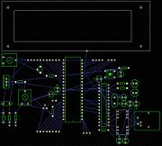
Integrated circuit layout
Integrated circuit layout, also known IC layout, IC mask layout, or mask design, is the representation of an integrated circuit in terms of planar geometric shapes which correspond to the patterns of metal, oxide, or semiconductor layers that make up the components of the integrated circuit.When...
artwork for the integrated circuit
Integrated circuit
An integrated circuit or monolithic integrated circuit is an electronic circuit manufactured by the patterned diffusion of trace elements into the surface of a thin substrate of semiconductor material...
or printed circuit board
Printed circuit board
A printed circuit board, or PCB, is used to mechanically support and electrically connect electronic components using conductive pathways, tracks or signal traces etched from copper sheets laminated onto a non-conductive substrate. It is also referred to as printed wiring board or etched wiring...
.
A generalized design flow would be as:
- Schematic → Schematic capture → Rat's nest → Routing → Artwork → PCB development & etching → Component mounting → Testing
See also
- DipTraceDipTraceDipTrace is EDA software for creating schematic diagrams and printed circuit boards. The first version of DipTrace was released in August, 2004. The latest version as of September 2011 is DipTrace version 2.2. Interface has been translated to many languages and new language can be added by user....
– Schematic Capture and PCB design software - EdwinxpEdwinxpEDWinXP or Electronic Design for Windows is a commercially available PCB design integrated CAD/CAE package. An electronic design engineer can use the computerized tools provided in EDWinXP to create an electronic circuit, design the PCB and fabricate PCBs...
– Totally Integrated Schematic Capture, Simulation Software and PCB design - Electronic symbol
- gEDAGEDAThe term gEDA refers to two things:# A set of software applications used for electronic design released under the GPL. As such, gEDA is an ECAD or EDA application suite. gEDA is mostly oriented towards printed circuit board design...
– GNU EDA-Tool used for schematic circuit design - KicadKicadKiCad is an open source software suite for electronic design automation . It facilitates the design of schematics for electronic circuits and their conversion to PCBs design. KiCad was developed by Jean-Pierre Charras, and features an integrated environment for schematic capture and PCB layout...
– GPL-ed EDA-Tool used for schematic circuit and PCBPrinted circuit boardA printed circuit board, or PCB, is used to mechanically support and electrically connect electronic components using conductive pathways, tracks or signal traces etched from copper sheets laminated onto a non-conductive substrate. It is also referred to as printed wiring board or etched wiring...
design - MultisimMultiSIMNI Multisim is an electronic schematic capture and simulation program which is part of a suite of circuit design programs, along with NI Ultiboard. Multisim is one of the few circuit design programs to employ the original Berkeley SPICE based software simulation...
Electronic schematic capture and simulation software - OrCADOrCADOrCAD is a proprietary software tool suite used primarily for electronic design automation. The software is used mainly to create electronic prints for manufacturing of printed circuit boards, by electronic design engineers and electronic technicians to manufacture electronic schematics.The name...
or Eagle (program)Eagle (program)EAGLE by Cadsoft is a flexible and expandable EDA schematic capture, PCB layout, autorouter and CAM program widely used since 1988.- Schematic capture :...
– Software for electronic schematics and for the design of printed circuit boards. - Schematic captureSchematic captureSchematic capture or schematic entry is a step in the design cycle of electronic design automation at which the electronic diagram, or electronic schematic of the designed electronic circuit is created by a designer...
- Schematic editorSchematic editorA Schematic editor is a tool for schematic capture of electrical circuits or electronic circuits.Schematic editors replaced manual drawing of schematic diagrams, but they still retain the capability of outputting schematics on specially formatted sheets...
- Wiring diagramWiring diagramA wiring diagram is a simplified conventional pictorial representation of an electrical circuit. It shows the components of the circuit as simplified shapes, and the power and signal connections between the devices. A wiring diagram usually gives more information about the relative position and...
- The schematic typically shows the pinoutPinoutIn electronics, a pinout is a cross-reference between the contacts, or pins, of an electrical connector or electronic component, and their functions.- Purpose :...
of each part.