
Pinout
Encyclopedia
In electronics
, a pinout (sometimes written "pin-out") is a cross-reference between the contacts, or pins, of an electrical connector
or electronic component
, and their functions.
While repairing electronic devices, an electronics technician uses electronic test equipment
to "pin out" each component on a PCB
. The technician probes each pin of the component in turn, comparing the expected signal on each pin to the actual signal on that pin.
USB
Viewed from the front (outside):
PS/2
Electronics
Electronics is the branch of science, engineering and technology that deals with electrical circuits involving active electrical components such as vacuum tubes, transistors, diodes and integrated circuits, and associated passive interconnection technologies...
, a pinout (sometimes written "pin-out") is a cross-reference between the contacts, or pins, of an electrical connector
Electrical connector
An electrical connector is an electro-mechanical device for joining electrical circuits as an interface using a mechanical assembly. The connection may be temporary, as for portable equipment, require a tool for assembly and removal, or serve as a permanent electrical joint between two wires or...
or electronic component
Electronic component
An electronic component is a basic electronic element and may be available in a discrete form having two or more electrical terminals . These are intended to be connected together, usually by soldering to a printed circuit board, in order to create an electronic circuit with a particular function...
, and their functions.
Purpose
The functions of contacts in electrical connectors, be they power- or signaling-related, must be specified in order for connectors to be interchangeable. When connected, each contact of a connector must mate with the contact on the other connector that has the same function. If contacts of disparate functions are allowed to make contact, the connection may fail and damage may result. Therefore, pinouts are a vital reference when building and testing connectors, cables, and adapters .Terminology
While one usage of the word pin is to refer to electrical contacts of, specifically, the male gender, its usage in pinout does not imply gender: the contact-to-function cross-reference for a connector that has only female socket contacts is still called a pinout.Representation
The pinout can typically be shown as a table or diagram, though it is necessary to clarify how to view the diagram, stating if it shows the backside of the connector (where wires are attached) or the "mating face" of the connector. Published pinouts, which are particularly important when different manufacturers want to interconnect their products using open standards, are typically provided by the connector or equipment manufacturer. Some pinouts are provided by 3rd parties since some connectors are not well documented by the manufacturer.While repairing electronic devices, an electronics technician uses electronic test equipment
Electronic test equipment
Electronic test equipment is used to create signals and capture responses from electronic Devices Under Test . In this way, the proper operation of the DUT can be proven or faults in the device can be traced and repaired...
to "pin out" each component on a PCB
Printed circuit board
A printed circuit board, or PCB, is used to mechanically support and electrically connect electronic components using conductive pathways, tracks or signal traces etched from copper sheets laminated onto a non-conductive substrate. It is also referred to as printed wiring board or etched wiring...
. The technician probes each pin of the component in turn, comparing the expected signal on each pin to the actual signal on that pin.
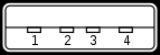
USBUniversal Serial BusUSB is an industry standard developed in the mid-1990s that defines the cables, connectors and protocols used in a bus for connection, communication and power supply between computers and electronic devices....
pinout
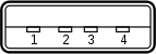
Viewed from the front (outside):
- +5V (Red)
- −Data (White)
- +Data (Green)
- GND (Black)
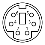
PS/2PS/2 connectorThe PS/2 connector is a 6-pin Mini-DIN connector used for connecting some keyboards and mice to a PC compatible computer system. Its name comes from the IBM Personal System/2 series of personal computers, with which it was introduced in 1987...
pinout
| Pin number | Name | Purpose |
|---|---|---|
| 1 | DATA | Data |
| 2 | Not used | |
| 3 | GND | Ground Ground (electricity) In electrical engineering, ground or earth may be the reference point in an electrical circuit from which other voltages are measured, or a common return path for electric current, or a direct physical connection to the Earth.... |
| 4 | Vcc | +5V Common-collector voltage VCC VCC may refer to:as a three-letter acronym:* Common-collector voltage , plus collector supply line voltage in a common NPN circuit.* Vale of Catmose College, an arts college in England.* Valencia Community College, in Orlando, Florida... |
| 5 | CLK | Clock signal Clock signal In electronics and especially synchronous digital circuits, a clock signal is a particular type of signal that oscillates between a high and a low state and is utilized like a metronome to coordinate actions of circuits... |
| 6 | Not used |
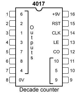
4017 decade counter
| Pin number | Name | Purpose |
|---|---|---|
| 1 | 6 | The 6th sequential output |
| 2 | 2 | The 2nd sequential output |
| 3 | 1 | The 1st sequential output |
| 4 | 3 | The 3rd sequential output |
| 5 | 7 | The 7th sequential output |
| 6 | 8 | The 8th sequential output |
| 7 | 4 | The 4th sequential output |
| 8 | 0 V, VDD | The connection to the 0 V rail |
| 9 | 9 | The 9th sequential output |
| 10 | 5 | The 5th sequential output |
| 11 | 10 | The 10th sequential output |
| 12 | CO | Carry out output - outputs high on counts 0 to 4, outputs low on counts 5 to 9 (thus a transition from low to high occurs when counting from 9 back to 0) |
| 13 | LE | Latch enable - latches on the current output when high (i.e. the chip counts when LE is low) |
| 14 | CLK | Clock in |
| 15 | RST | Reset - sets output 1 high and outputs 2 through 10 low, when taken high |
| 16 | +9 V, VCC | The connection to the +VCC rail (voltage between +3 V and +15 V) |
See also
- DatasheetDatasheetthumb|A floppy disk controller datasheet.A datasheet, data sheet, or spec sheet is a document summarizing the performance and other technical characteristics of a product, machine, component , material, a subsystem or software in sufficient detail to be used by a design engineer to integrate the...
- Piping and instrumentation diagramPiping and instrumentation diagramA piping and instrumentation diagram/drawing is a diagram in the process industry which shows the piping of the process flow together with the installed equipment and instrumentation.-Contents and Function:...
- Circuit diagramCircuit diagramA circuit diagram is a simplified conventional graphical representation of an electrical circuit...
- SchematicSchematicA schematic diagram represents the elements of a system using abstract, graphic symbols rather than realistic pictures. A schematic usually omits all details that are not relevant to the information the schematic is intended to convey, and may add unrealistic elements that aid comprehension...
External links
- The Hardware Book - Pinout collection
- Crossover search of pinouts at pinout.net
- Pinouts of hardware connectors with description of common interfaces at pinouts.ru
- Pinouts (pin-out) - Historical Pinouts collection
- 74xxx and 40xx (pin-outs) - Pinouts collection