
Current-to-voltage converter
Encyclopedia
In electronics
, a transimpedance amplifier is an amplifier that converts current to voltage. Its input ideally has zero impedance
, and the input signal is a current. Its output may have low impedance, or in high-frequency applications, may be matched to a driven transmission line
; the output signal is measured as a voltage
.
Because the output is a voltage and the input is a current, the gain, or ratio of output to input, is expressed in units of ohms.
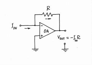
When constructed as a simple operational amplifier
circuit (right), the gain is equal to the negative of feedback resistance.
Transimpedance amplifiers are commonly used in receivers for optical communications to convert the current generated by a photodetector
into a voltage signal for further amplification.
generates photo voltage, but in a nonlinear fashion. Therefore the amplifier has to prevent any large voltage by its low input impedance and generate either a 50 Ohm signal (considered low impedance by many) to drive a coaxial cable
or a voltage signal for further amplification. But note that the most linear amplification is current amplification by a bipolar transistor, so you may want to amplify before the impedance conversion.
In this arrangement, the flow-, pressure-, and impediment-like attributes are interrelated. Usually, the output pressure-like variable is proportional to the input flow-like one; in this way, the flow-like quantity creates (is converted to) a pressure-like one.
To induce pressure, an impediment must be put in the way of a flowing quantity.
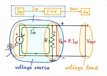
VR = R.IIN appears across the resistor according to current-causes-voltage formulation of Ohm's law
(V = R.I). In this current-supplied circuit, the voltage drop VR acts as an output voltage VOUT (the voltage drop VR is created not by the resistor; it is created by the excitation voltage source inside the input current source
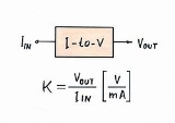
). In this way, the current IIN is converted to a proportional voltage VOUT; the resistor R serves as a current-to-voltage converter - a linear circuit with transfer ratio k = VOUT/IIN [V/mA] having dimensions of resistance.
Circuit operation. Fig. 2 represents graphically the circuit operation by using a current loop and voltage bars. The thickness of the current loop is proportional to the magnitude of the current and the height of the voltage bars is proportional to the corresponding voltages (see also an interactive animation).
A graphoanalytical interpretation of the circuit (and of the Ohm's law) is shown on Fig. 3. As the current through and the voltage across the two components (the current source and the resistor) are the same, their IV curves are superimposed on a common coordinate system. The intersection of the two lines is the operating point A; it represents the present magnitudes of the current IA and the voltage VA. When the current IIN of the input current source varies, its IV curve moves vertically (see also an interactive animation). As a result, the working point A slides over the IV curve of the resistor R; its slope represents the converter's ratio.
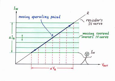
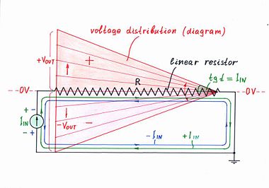 Fig. 4 shows another attractive graphical interpretation of Ohm's law - the voltage diagram (the voltage distribution along the resistive film inside a linear resistor). When the input current varies, the local voltages along the resistive film vary decreasing gradually from left to right (see also another interactive animation). In this arrangement, the angle α represents the input current IIN.
 Current-controlled voltage source. Although there are enough constant voltage source
s in nature (primary and secondary batteries), if a current source is available but there is a need of a voltage source, it may be built. For this purpose, a current-to-voltage converter has to be connected after the current source, according to the building formula below:
Voltage source = Current source + Current-to-voltage converter
The simplest implementation of this idea is shown in Fig. 5 where a resistor R is connected in parallel to the input current source IIN (the Norton's idea in electricity).
If the load is ideal (that is, it has an infinite resistance), a constant voltage VOUT = R.IIN will be generated. This voltage will affect the current, if the input current source is imperfect (see the section below about passive version imperfections).
Compound passive converters: Similarly, in the popular passive circuits of capacitive differentiator
, inductive integrator
, antilogarithmic converter, etc., the resistor acts as a current-to-voltage converter:
V-to-V CR differentiator = V-to-I C differentiator + I-to-V converter
V-to-V LR integrator = V-to-I L integrator + I-to-V converter
V-to-V DR antilog converter = V-to-I D antilog converter + I-to-V
For example, a classic capacitive-resistive differentiator is built on Fig. 6 by using the simpler voltage-to-current capacitive differentiator (a bare capacitor) and a current-to-voltage converter.
In these circuits, the resistor R acting as a current-to-voltage converter introduces some voltage drop VR, which affects the excitation voltage VIN. As a result, the current decreases and an error appears (see the section about passive version imperfections).
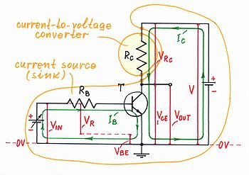 Transistor collector resistor. A transistor is a current-controlling device. Therefore, to obtain a voltage as an output, a collector resistor is connected in the output circuit of the transistor stage (Fig. 7). Examples of this technique are the common-emitter, common-base and differential amplifier, a transistor switch, etc.
Voltage-output transistor = Current-output transistor + I-to-V converter
The transistor's collector resistor acts as a current-to-voltage converter.
Since the voltage drop VRc is floating, usually the complementary (to the power supply) voltage drop VCE is used as an output. As a result, these transistor circuits are inverting (when the input voltage rises, the output voltage drops and v.v.)
A similar technique is used to obtain a voltage in the transistor emitter (see the section below about negative feedback current source). Examples of this technique are all the transistor circuits using series negative feedback.
The transistor's emitter resistor acts as a current-to-voltage converter.
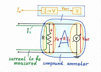 Compound ammeter. Today's measuring instruments (DVM's, analog-to-digital converters, etc.) are mainly voltmeters. If there is a need to measure a current, a simple current-to-voltage converter (a shunt resistor) is connected before the voltmeter (Fig. 8). This ammeter is a composed device consisting of two components:
Compound ammeter = Current-to-voltage converter + voltmeter
The shunt resistor of a composed ammeter acts as a current-to-voltage converter.
Although the active version is the perfect current measurement solution, the popular multimeter
s use the passive version to measure big currents (see the section about power considerations below).
systems have the unique property to reverse the causality in the electronic converters connected in the feedback loop. Examples: an op-amp non-inverting amplifier is actually a reversed voltage divider, an op-amp integrator
is a reversed differentiator
and v.v., an op-amp logarithmic converter is a reversed antilogarithmic converter and v.v., etc.
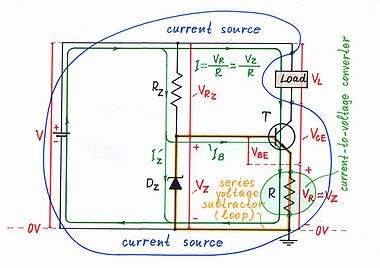
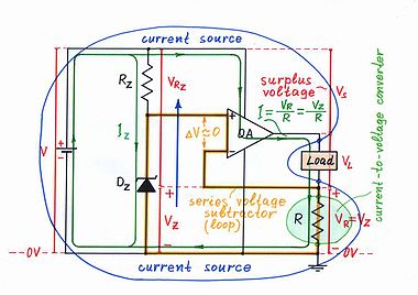
Similarly, an op-amp voltage-to-current converter (a voltage-controlled constant current source) built by using a negative feedback is actually a reversed current-to-voltage converter. This powerful idea is implemented on Fig. 9 (a transistor version of a current source) and on Fig. 10 (an op-amp version of a current source) where a current-to-voltage converter (the bare resistor R) is connected in the negative feedback loop. The voltage drop VR proportional to the load current I is compared with the input voltage VZ. For this purpose, the two voltages are connected in series and their difference dV = VZ - VR is applied to the input part of the regulating element (the base-emitter junction of the transistor T or the differential input of the op-amp OA). As a result, the regulating element establishes the current I = VR/R ≈ VZ/R by changing its output resistance so that to zero the voltage difference dV. In this way, the output current is proportional to the input voltage; the whole circuit acts as a voltage-to-current converter.
 The passive current-to-voltage converter (as all the passive circuits) is imperfect because of two reasons:
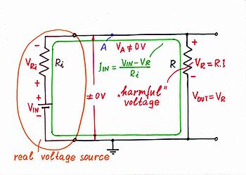
Resistor R. The voltage drop VR affects the input current IIN as the resistor R consumes energy from the input source (Fig. 11). A contradiction exists in this circuit: from one side, the voltage drop VR is useful as it serves as an output voltage; from the other side, this voltage drop is harmful as it effectively modifies the actual current-creating voltage VRi. In this arrangement, the voltage difference VIN - VR determines the current instead the voltage VIN (the resistor Ri actually acts as the opposite voltage-to-current converter). As a result, the current decreases.
Load resistance. In addition, if the load has some finite resistance (instead of infinite resistance), a part of the current IIN will diverts through it. As a result, both the current IIN and the voltage VOUT decrease. The problem is again that the load consumes energy from the passive circuit (click Imperfections in http://www.circuit-fantasia.com/collections/circuit-collection/circuits/old-circuits/i-to-v-old.html).
source, which "helps" the main source by compensating the local losses caused by the internal undesired quantity (conversely, in the opposite active voltage-to-current converter, the additional power source compensates the losses caused by the external quantity). Example: if we have broken our window in winter, we turn on a heater that compensates the thermal losses; and v.v., in summer, we turn on an air-conditioner. More examples: if our car has come into collision with other car, the insurance company compensates the damages we caused to the other car. If we cause trouble to others, we apologize. If we spend money from an account, we deposit funds. (See virtual ground page for more examples.) In all these cases, we prepared "standby" resources to use if there is a need to compensate internal losses.
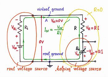 Electrical implementation. To show how this powerful basic idea is applied to improve the passive current-to-voltage converter, first, an equivalent electrical circuit is used (Fig. 12). In this active current-to-voltage converter, the voltage drop VR across the internal resistor R is compensated by adding the same voltage VH = VR to the input voltage VIN http://circuit-fantasia.com/circuit_stories/inventing_circuits/transimpedance_amplifier/transimpedance_amplifier.htm#step3. For this purpose, an additional following voltage source BH is connected in series with the resistor. It "helps" the input voltage source; as a result, the undesired voltage VR and the resistance R disappear (the point A becomes a virtual ground
).
Active I-to-V converter = passive I-to-V converter + "helping" voltage source
Where to take an output from? The magnitude of the compensating quantity is frequently used to measure indirectly the initial quantity (an example - weighing by using scales). This idea is applied in the circuit of active current-to-voltage converter by connecting the load to the compensating voltage source BH instead to the resistor. There are two advantages of this arrangement: first, the load is connected to the common ground; second, it consumes energy
from the additional source instead from the input source. Therefore, it might possess small resistance.
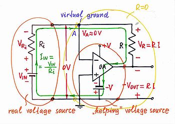
The basic idea above is implemented in the op-amp current-to-voltage converter (Fig. 13, 14) http://circuit-fantasia.com/circuit_stories/inventing_circuits/transimpedance_amplifier/transimpedance_amplifier.htm#step7. In this circuit, the output of the operational amplifier
is connected in series with the input voltage source; the op-amp's inverting input is connected to point A. As a result, the op-amp's output voltage and the input voltage are summed.
From other viewpoint, the output of the operational amplifier
is connected in series with the resistor R in the place of the compensating voltage source BH from Fig. 12. As a result, the op-amp's output voltage and the voltage drop VR are subtracted; the potential of the point A represents the result of this subtraction
(it behaves as a virtual ground
).
Op-amp I-to-V converter = passive I-to-V converter + "helping" op-amp
 Zero input voltage results in no voltage drops or currents in the circuit (click Exploring in http://www.circuit-fantasia.com/collections/circuit-collection/circuits/old-circuits/v-to-v-active-sum-old.html).
Positive input voltage. If the input voltage VIN increases above the ground, an input current IIN begins flowing through the resistor R. As a result, a voltage drop VR appears across the resistor and the point A begins raising its potential (the input source "pulls" the point A up toward the positive voltage VIN). Only, the op-amp "observes" that and immediately reacts: it decreases its output voltage under the ground sucking the current. Figuratively speaking, the op-amp "pulls" the point A down toward the negative voltage -V until it manages to zero its potential (to establish a virtual ground
). It does this work by connecting a portion of the voltage produced by the negative power supply -V in series with the input voltage VIN. The two voltage sources are connected in series, in the same direction (traversing the loop clockwise, the signs are - VIN +, - VOA +) so that their voltages are added. However, regarding to the ground, they have opposite polarities.
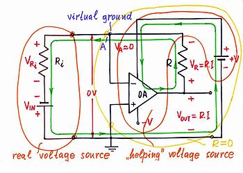 Negative input voltage. If the input voltage VIN decreases under the ground, the input current flows through the resistor R in opposite direction (Fig. 15). As a result, a voltage drop VR appears across the resistor again and the point A begins dropping its potential (now, the input source "pulls" the point A down toward the negative voltage -VIN). The op-amp "observes"' that and immediately reacts: it increases its output voltage above the ground "pushing out" the current. Now, the op-amp "pulls" the point A up toward the positive voltage +V until it manages to zero again the potential VA (the virtual ground). For this purpose, the op-amp puts a portion of the voltage produced by the positive power supply +V in series with the input voltage VIN. The two voltage sources are connected again, in the same direction (traversing the loop clockwise, + VIN -, + VOA -) so that their voltages are added. However, regarding to the ground, they have opposite polarities as above.
Conclusion. In the circuit of an op-amp current-to-voltage converter, the op-amp adds as much voltage to the voltage of the input source as it loses across the resistor. The op-amp compensates the local losses caused by this internal resistor (conversely, in the opposite op-amp voltage-to-current converter, the op-amp compensates the losses caused by the external load).
Electronics
Electronics is the branch of science, engineering and technology that deals with electrical circuits involving active electrical components such as vacuum tubes, transistors, diodes and integrated circuits, and associated passive interconnection technologies...
, a transimpedance amplifier is an amplifier that converts current to voltage. Its input ideally has zero impedance
Electrical impedance
Electrical impedance, or simply impedance, is the measure of the opposition that an electrical circuit presents to the passage of a current when a voltage is applied. In quantitative terms, it is the complex ratio of the voltage to the current in an alternating current circuit...
, and the input signal is a current. Its output may have low impedance, or in high-frequency applications, may be matched to a driven transmission line
Transmission line
In communications and electronic engineering, a transmission line is a specialized cable designed to carry alternating current of radio frequency, that is, currents with a frequency high enough that its wave nature must be taken into account...
; the output signal is measured as a voltage
Voltage
Voltage, otherwise known as electrical potential difference or electric tension is the difference in electric potential between two points — or the difference in electric potential energy per unit charge between two points...
.
Because the output is a voltage and the input is a current, the gain, or ratio of output to input, is expressed in units of ohms.
When constructed as a simple operational amplifier
Operational amplifier
An operational amplifier is a DC-coupled high-gain electronic voltage amplifier with a differential input and, usually, a single-ended output...
circuit (right), the gain is equal to the negative of feedback resistance.
Transimpedance amplifiers are commonly used in receivers for optical communications to convert the current generated by a photodetector
Photodetector
Photosensors or photodetectors are sensors of light or other electromagnetic energy. There are several varieties:*Active pixel sensors are image sensors consisting of an integrated circuit that contains an array of pixel sensors, each pixel containing a both a light sensor and an active amplifier...
into a voltage signal for further amplification.
Application
Transimpedance amplifiers are commonly used in receivers for optical communications. The current generated by a photodetectorPhotodetector
Photosensors or photodetectors are sensors of light or other electromagnetic energy. There are several varieties:*Active pixel sensors are image sensors consisting of an integrated circuit that contains an array of pixel sensors, each pixel containing a both a light sensor and an active amplifier...
generates photo voltage, but in a nonlinear fashion. Therefore the amplifier has to prevent any large voltage by its low input impedance and generate either a 50 Ohm signal (considered low impedance by many) to drive a coaxial cable
Coaxial cable
Coaxial cable, or coax, has an inner conductor surrounded by a flexible, tubular insulating layer, surrounded by a tubular conducting shield. The term coaxial comes from the inner conductor and the outer shield sharing the same geometric axis...
or a voltage signal for further amplification. But note that the most linear amplification is current amplification by a bipolar transistor, so you may want to amplify before the impedance conversion.
Non-electrical domain: Flow causes pressure
In physical terms, there are many situations where a pressure-like quantity induces flow of a substance through an impediment. However, there are also corresponding situations where a flow-like quantity induces pressure at an impediment: mechanical (if one tries to stop a moving car with his body, the "flowing" car exerts pressure on him, the impediment), pneumatic (pinch a hose in the middle and you will see that a pressure appears at the pinch point).In this arrangement, the flow-, pressure-, and impediment-like attributes are interrelated. Usually, the output pressure-like variable is proportional to the input flow-like one; in this way, the flow-like quantity creates (is converted to) a pressure-like one.
To induce pressure, an impediment must be put in the way of a flowing quantity.
Electrical domain: Current causes voltage
Building the circuit. Similarly, in electricity, if a current IIN flows through a resistor R (Fig. 2), the latter impedes (resists) the current; as a result, a proportional voltage dropVoltage drop
Voltage drop is the reduction in voltage in the passive elements of an electrical circuit. Voltage drops across conductors, contacts, connectors and source internal resistances are undesired as they reduce the supplied voltage while voltage drops across loads and other electrical and electronic...
VR = R.IIN appears across the resistor according to current-causes-voltage formulation of Ohm's law
Ohm's law
Ohm's law states that the current through a conductor between two points is directly proportional to the potential difference across the two points...
(V = R.I). In this current-supplied circuit, the voltage drop VR acts as an output voltage VOUT (the voltage drop VR is created not by the resistor; it is created by the excitation voltage source inside the input current source
Current source
A current source is an electrical or electronic device that delivers or absorbs electric current. A current source is the dual of a voltage source. The term constant-current sink is sometimes used for sources fed from a negative voltage supply...
). In this way, the current IIN is converted to a proportional voltage VOUT; the resistor R serves as a current-to-voltage converter - a linear circuit with transfer ratio k = VOUT/IIN [V/mA] having dimensions of resistance.
Circuit operation. Fig. 2 represents graphically the circuit operation by using a current loop and voltage bars. The thickness of the current loop is proportional to the magnitude of the current and the height of the voltage bars is proportional to the corresponding voltages (see also an interactive animation).
A graphoanalytical interpretation of the circuit (and of the Ohm's law) is shown on Fig. 3. As the current through and the voltage across the two components (the current source and the resistor) are the same, their IV curves are superimposed on a common coordinate system. The intersection of the two lines is the operating point A; it represents the present magnitudes of the current IA and the voltage VA. When the current IIN of the input current source varies, its IV curve moves vertically (see also an interactive animation). As a result, the working point A slides over the IV curve of the resistor R; its slope represents the converter's ratio.
I-to-V converter acting as an output device
Voltage source
In electric circuit theory, an ideal voltage source is a circuit element where the voltage across it is independent of the current through it. A voltage source is the dual of a current source. In analysis, a voltage source supplies a constant DC or AC potential between its terminals for any current...
s in nature (primary and secondary batteries), if a current source is available but there is a need of a voltage source, it may be built. For this purpose, a current-to-voltage converter has to be connected after the current source, according to the building formula below:
Voltage source = Current source + Current-to-voltage converter
The simplest implementation of this idea is shown in Fig. 5 where a resistor R is connected in parallel to the input current source IIN (the Norton's idea in electricity).
If the load is ideal (that is, it has an infinite resistance), a constant voltage VOUT = R.IIN will be generated. This voltage will affect the current, if the input current source is imperfect (see the section below about passive version imperfections).
Compound passive converters: Similarly, in the popular passive circuits of capacitive differentiator
Differentiator
A Differentiator is a circuit that is designed such that the output of the circuit is proportional to the time derivative of the input. There are two types of differentiator circuits, active and passive.-Theory:...
, inductive integrator
Integrator
An integrator is a device to perform the mathematical operation known as integration, a fundamental operation in calculus.The integration function is often part of engineering, physics, mechanical, chemical and scientific calculations....
, antilogarithmic converter, etc., the resistor acts as a current-to-voltage converter:
V-to-V CR differentiator = V-to-I C differentiator + I-to-V converter
V-to-V LR integrator = V-to-I L integrator + I-to-V converter
V-to-V DR antilog converter = V-to-I D antilog converter + I-to-V
For example, a classic capacitive-resistive differentiator is built on Fig. 6 by using the simpler voltage-to-current capacitive differentiator (a bare capacitor) and a current-to-voltage converter.
In these circuits, the resistor R acting as a current-to-voltage converter introduces some voltage drop VR, which affects the excitation voltage VIN. As a result, the current decreases and an error appears (see the section about passive version imperfections).
Voltage-output transistor = Current-output transistor + I-to-V converter
The transistor's collector resistor acts as a current-to-voltage converter.
Since the voltage drop VRc is floating, usually the complementary (to the power supply) voltage drop VCE is used as an output. As a result, these transistor circuits are inverting (when the input voltage rises, the output voltage drops and v.v.)
A similar technique is used to obtain a voltage in the transistor emitter (see the section below about negative feedback current source). Examples of this technique are all the transistor circuits using series negative feedback.
The transistor's emitter resistor acts as a current-to-voltage converter.
I-to-V converter acting as an input device
Compound ammeter = Current-to-voltage converter + voltmeter
The shunt resistor of a composed ammeter acts as a current-to-voltage converter.
Although the active version is the perfect current measurement solution, the popular multimeter
Multimeter
A multimeter or a multitester, also known as a VOM , is an electronic measuring instrument that combines several measurement functions in one unit. A typical multimeter may include features such as the ability to measure voltage, current and resistance...
s use the passive version to measure big currents (see the section about power considerations below).
I-to-V converter as a part of negative feedback V-to-I converters
Negative feedbackNegative feedback
Negative feedback occurs when the output of a system acts to oppose changes to the input of the system, with the result that the changes are attenuated. If the overall feedback of the system is negative, then the system will tend to be stable.- Overview :...
systems have the unique property to reverse the causality in the electronic converters connected in the feedback loop. Examples: an op-amp non-inverting amplifier is actually a reversed voltage divider, an op-amp integrator
Integrator
An integrator is a device to perform the mathematical operation known as integration, a fundamental operation in calculus.The integration function is often part of engineering, physics, mechanical, chemical and scientific calculations....
is a reversed differentiator
Differentiator
A Differentiator is a circuit that is designed such that the output of the circuit is proportional to the time derivative of the input. There are two types of differentiator circuits, active and passive.-Theory:...
and v.v., an op-amp logarithmic converter is a reversed antilogarithmic converter and v.v., etc.
Similarly, an op-amp voltage-to-current converter (a voltage-controlled constant current source) built by using a negative feedback is actually a reversed current-to-voltage converter. This powerful idea is implemented on Fig. 9 (a transistor version of a current source) and on Fig. 10 (an op-amp version of a current source) where a current-to-voltage converter (the bare resistor R) is connected in the negative feedback loop. The voltage drop VR proportional to the load current I is compared with the input voltage VZ. For this purpose, the two voltages are connected in series and their difference dV = VZ - VR is applied to the input part of the regulating element (the base-emitter junction of the transistor T or the differential input of the op-amp OA). As a result, the regulating element establishes the current I = VR/R ≈ VZ/R by changing its output resistance so that to zero the voltage difference dV. In this way, the output current is proportional to the input voltage; the whole circuit acts as a voltage-to-current converter.
Passive version imperfections
Resistor R. The voltage drop VR affects the input current IIN as the resistor R consumes energy from the input source (Fig. 11). A contradiction exists in this circuit: from one side, the voltage drop VR is useful as it serves as an output voltage; from the other side, this voltage drop is harmful as it effectively modifies the actual current-creating voltage VRi. In this arrangement, the voltage difference VIN - VR determines the current instead the voltage VIN (the resistor Ri actually acts as the opposite voltage-to-current converter). As a result, the current decreases.
Load resistance. In addition, if the load has some finite resistance (instead of infinite resistance), a part of the current IIN will diverts through it. As a result, both the current IIN and the voltage VOUT decrease. The problem is again that the load consumes energy from the passive circuit (click Imperfections in http://www.circuit-fantasia.com/collections/circuit-collection/circuits/old-circuits/i-to-v-old.html).
Non-electrical domain: Removing disturbance by equivalent "antidisturbance"
The active version of the current-to-voltage converter is based on a well-known technique from human routine, where we compensate the undesirable effects caused by ourselves using equivalent "anti-quantities". This idea is implemented by using an additional powerPower (physics)
In physics, power is the rate at which energy is transferred, used, or transformed. For example, the rate at which a light bulb transforms electrical energy into heat and light is measured in watts—the more wattage, the more power, or equivalently the more electrical energy is used per unit...
source, which "helps" the main source by compensating the local losses caused by the internal undesired quantity (conversely, in the opposite active voltage-to-current converter, the additional power source compensates the losses caused by the external quantity). Example: if we have broken our window in winter, we turn on a heater that compensates the thermal losses; and v.v., in summer, we turn on an air-conditioner. More examples: if our car has come into collision with other car, the insurance company compensates the damages we caused to the other car. If we cause trouble to others, we apologize. If we spend money from an account, we deposit funds. (See virtual ground page for more examples.) In all these cases, we prepared "standby" resources to use if there is a need to compensate internal losses.
Electrical domain: Removing voltage by equivalent "antivoltage"
Virtual ground
Virtual ground is a node of the circuit that is maintained at a steady reference potential, without being connected directly to the reference potential...
).
Active I-to-V converter = passive I-to-V converter + "helping" voltage source
Where to take an output from? The magnitude of the compensating quantity is frequently used to measure indirectly the initial quantity (an example - weighing by using scales). This idea is applied in the circuit of active current-to-voltage converter by connecting the load to the compensating voltage source BH instead to the resistor. There are two advantages of this arrangement: first, the load is connected to the common ground; second, it consumes energy
Energy
In physics, energy is an indirectly observed quantity. It is often understood as the ability a physical system has to do work on other physical systems...
from the additional source instead from the input source. Therefore, it might possess small resistance.
Op-amp implementation
The basic idea above is implemented in the op-amp current-to-voltage converter (Fig. 13, 14) http://circuit-fantasia.com/circuit_stories/inventing_circuits/transimpedance_amplifier/transimpedance_amplifier.htm#step7. In this circuit, the output of the operational amplifier
Operational amplifier
An operational amplifier is a DC-coupled high-gain electronic voltage amplifier with a differential input and, usually, a single-ended output...
is connected in series with the input voltage source; the op-amp's inverting input is connected to point A. As a result, the op-amp's output voltage and the input voltage are summed.
From other viewpoint, the output of the operational amplifier
Operational amplifier
An operational amplifier is a DC-coupled high-gain electronic voltage amplifier with a differential input and, usually, a single-ended output...
is connected in series with the resistor R in the place of the compensating voltage source BH from Fig. 12. As a result, the op-amp's output voltage and the voltage drop VR are subtracted; the potential of the point A represents the result of this subtraction
Subtraction
In arithmetic, subtraction is one of the four basic binary operations; it is the inverse of addition, meaning that if we start with any number and add any number and then subtract the same number we added, we return to the number we started with...
(it behaves as a virtual ground
Virtual ground
Virtual ground is a node of the circuit that is maintained at a steady reference potential, without being connected directly to the reference potential...
).
Op-amp I-to-V converter = passive I-to-V converter + "helping" op-amp
Op-amp circuit operation
Positive input voltage. If the input voltage VIN increases above the ground, an input current IIN begins flowing through the resistor R. As a result, a voltage drop VR appears across the resistor and the point A begins raising its potential (the input source "pulls" the point A up toward the positive voltage VIN). Only, the op-amp "observes" that and immediately reacts: it decreases its output voltage under the ground sucking the current. Figuratively speaking, the op-amp "pulls" the point A down toward the negative voltage -V until it manages to zero its potential (to establish a virtual ground
Virtual ground
Virtual ground is a node of the circuit that is maintained at a steady reference potential, without being connected directly to the reference potential...
). It does this work by connecting a portion of the voltage produced by the negative power supply -V in series with the input voltage VIN. The two voltage sources are connected in series, in the same direction (traversing the loop clockwise, the signs are - VIN +, - VOA +) so that their voltages are added. However, regarding to the ground, they have opposite polarities.
Conclusion. In the circuit of an op-amp current-to-voltage converter, the op-amp adds as much voltage to the voltage of the input source as it loses across the resistor. The op-amp compensates the local losses caused by this internal resistor (conversely, in the opposite op-amp voltage-to-current converter, the op-amp compensates the losses caused by the external load).
I-to-V converters versus transimpedance amplifiers
The active current-to-voltage converter is an amplifier with current input and voltage output. The gain of this amplifier is represented by the resistance R (K = VOUT/IIN = R); it is expressed in units of ohms. That is why this circuit is named transresistance amplifier or more generally, transimpedance amplifier http://www.elecdesign.com/Articles/Index.cfm?AD=1&ArticleID=4346. Both terms are used to designate the circuit considered.See also
- Virtual groundVirtual groundVirtual ground is a node of the circuit that is maintained at a steady reference potential, without being connected directly to the reference potential...
, Voltage-to-current converter - Miller theorem applications