
Conical scanning
Encyclopedia
Conical scanning is a system used in early radar
units to improve their accuracy, as well as making it easier to steer the antenna
properly to point at a target. Conical scanning is similar in concept to the earlier lobe switching
concept used on some of the earliest radars, and many examples of lobe switching sets were modified in the field to conical scanning during World War II
, notably the German Würzburg radar
. With simple electronics, antenna guidance can be made entirely automatic, although potential failure modes and susceptibility to deception jamming led to the replacement of conical scan systems with monopulse radar
sets.
, which demands accuracies on the order of 0.1 degrees. It is possible to improve the beam width through the use of larger antennas, but this is often impractical.
In order to monitor the direction of a designated target, it is only necessary to keep the aerial pointing directly at the target. Knowledge of the pointing direction of the aerial then naturally gives knowledge of the target direction. In order to have the radar system follow a moving target automatically, it is necessary to have a control system that keeps the aerial beam pointing at it as it moves. The radar receiver will get maximum returned signal strength when the target is in the beam centre, So if the beam is pointed directly at the target, when the target moves it will move out of the beam center and the received signal strength will fall. Circuitry designed to monitor any fall off in received signal strength could be used to control a servo motor that steers the aerial to follow the target motion. There are three difficulties with this method:
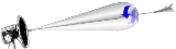
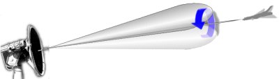 Conical scanning addresses this problem by "moving" the radar beam slightly off center from the antenna's midline, and then rotating it. Given an example antenna that generates a beam of 2 degrees width – fairly typical – a conical scanning radar might move the beam 1.5 degrees to one side of the centerline by offsetting the feed slightly. The resulting pattern, at any one instant in time, covers the midline of the antenna for about 0.5 degrees, and 1.5 degrees to the side. By spinning the feed horn with a motor, the pattern becomes a cone centered on the midline, extending 3 degrees to the sides in our example.
The key concept is that a target located at the midline point will generate a constant return no matter where the lobe is currently pointed, whereas if it is to one side it will generate a strong return when the lobe is pointed in that general direction and a weak one when pointing away. Additionally the portion covering the centerline is near the edge of the radar lobe, where sensitivity is falling off rapidly. An aircraft centered in the beam is in the area where even small motions will result in a noticeable change in return, growing much stronger along the direction the radar needs to move. The antenna control system is arranged to move the antenna in azimuth and elevation such that a constant return is obtained from the aircraft being tracked. Whilst use of the lobe alone might allow an operator to "hunt" for the strongest return and thus aim the antenna within a degree or so in that "maximum return" area at the center of the lobe, with conical scanning much smaller movements can be detected, and accuracies under 0.1 degree were possible.
The primary difference between the two basic schemes is in polarization. As the feed horn in the rotated process spins, the polarization changes with the rotation and will thus be 90 degrees off in polarization when the feed is 90 degrees off its initial axis. As the feed horn is fixed in nutated feeds, no polarization changes occur. Most early systems used a rotated feed, due to its mechanical simplicity, but later systems often used nutated feeds in order to use the polarization information.
In the U.S. Navy Mk. 25 gun fire control radar, spiral scan mode aided target acquisition. Basically conical scan (of the non-revolving nutating feed type), the size of the scan cone cyclically increased and decreased roughly twice a second. The scanned area was several degrees, in all. (Once the target was acquired, the operator switched to conical scan for tracking.)
Since the lobe is being rotated around the midline of the antenna, conical scanning is only really appropriate for antennas with a circular cross section. This was the case for the Würzburg, which operated in the microwave
region. Most other forces used much longer-wavelength radars that would require paraboloid
antennas of truly enormous size, and instead used a "bedspring" arrangement of many small dipole antenna
s arranged in front of a passive reflector. To arrange conical scanning on such a system would require all of the dipoles to be moved, an impractical solution. For this reason the US Army simply abandoned their early gun laying radar, the SCR-268
. This was not particularly annoying, given that they were in the process of introducing their own microwave radar in the aftermath of the Tizard Mission
, the SCR-584
.
Automatic guidance for the antenna, and thus any slaved guns or weapons, can be added to a conical scan radar without too much trouble. The control system has to steer the antenna such that a constant amplitude return is received from the target.
Unfortunately there are a number of factors that can dramatically change the reflected signal. For instance, changes in the target aircraft's direction can present different portions of the fuselage
to the antenna, and dramatically change the amount of signal being returned. In these cases, a conical scan radar might interpret this change in strength as a change in position. For instance, if the aircraft were to suddenly "brighten" when it was off-axis to the left, the circuitry might interpret this as being off to the right if the change occurs when the lobe is aligned in that direction. This problem can be solved by using two simultaneous overlapping receiver beams leading to the monopulse radar
, so-named because it always compares signal strength from a single pulse against itself, thereby eliminating problems with all but impossibly fast changes in signal strength.
Antenna waveguide in COSRO systems includes an RF received feedhorn structure that produces a left/right RF receive sample and an up/down RF receive sample. These two signals are multiplexed inside a waveguide device that has a rotating vane. The output of the multiplex device is a single RF signal and two position signals that indicate left/right and up/down.
The COSRO technique does not transmit any signals that indicate the position of the rotating vane.
This produces a pair of angle error signals used to drive antenna positioning drive motors.
. If the target knows the general operating parameters of the radar, it is possible to send out a false signal timed to grow and fade in the same pattern as the radar lobe, but inverted in strength. That is, the false signal is at its strongest when the radar signal is the weakest (the lobe is on the "far side" of the antenna compared to the aircraft), and weakest when the signal is the strongest (pointed at the aircraft). When added together with the "real" signal at the radar receiver, the resulting signal is "always strong", so the control system cannot make an accurate estimate as to where in the lobe pattern the target is located.
Actually accomplishing this in hardware is not as difficult as it may sound. If one knows that the signal is rotated at 25 RPM, as it was in the Würzburg radar, the jammer is built to fade from maximum to zero at the same speed, 25 times a second. Then all that is needed is to sync the signals up, which is accomplished by looking for the low point in the signal (which is generally easier to find) and triggering the pattern at that point. This system, known as inverse gain jamming, was used operationally by the Royal Air Force
against the Würzburg radar during WWII.
It is possible to arrange a radar so the lobes are not being moved in the broadcaster, only the receiver. To do this, one adds a second antenna with the rotating lobe for reception only, a system known as COSRO, for Conical Scan on Receive Only (compare to LORO, a similar system used against lobe switching
radars). Although this denied lobing frequency information to the jammer in the aircraft, it was still possible to simply send out random spikes and thereby confuse the tracking system (or operator). This technique, called SSW for Swept Square Wave, doesn't protect the aircraft with the same sort of effectiveness as inverse gain, but is better than nothing and often fairly effective.
Radar
Radar is an object-detection system which uses radio waves to determine the range, altitude, direction, or speed of objects. It can be used to detect aircraft, ships, spacecraft, guided missiles, motor vehicles, weather formations, and terrain. The radar dish or antenna transmits pulses of radio...
units to improve their accuracy, as well as making it easier to steer the antenna
Antenna (radio)
An antenna is an electrical device which converts electric currents into radio waves, and vice versa. It is usually used with a radio transmitter or radio receiver...
properly to point at a target. Conical scanning is similar in concept to the earlier lobe switching
Lobe switching
Lobe switching is a method used on early radar sets to improve tracking accuracy. It used two slightly separated antenna elements to send the beam slightly to either side of the midline of the antenna, switching between the two to find which one gave the stronger return, thereby indicating which...
concept used on some of the earliest radars, and many examples of lobe switching sets were modified in the field to conical scanning during World War II
World War II
World War II, or the Second World War , was a global conflict lasting from 1939 to 1945, involving most of the world's nations—including all of the great powers—eventually forming two opposing military alliances: the Allies and the Axis...
, notably the German Würzburg radar
Würzburg radar
The Würzburg radar was the primary ground-based gun laying radar for both the Luftwaffe and the German Army during World War II. Initial development took place before the war, entering service in 1940. Eventually over 4,000 Würzburgs of various models were produced...
. With simple electronics, antenna guidance can be made entirely automatic, although potential failure modes and susceptibility to deception jamming led to the replacement of conical scan systems with monopulse radar
Monopulse radar
Monopulse radar is an adaptation of conical scanning radar which sends additional information in the radar signal in order to avoid problems caused by rapid changes in signal strength. The system also makes jamming more difficult...
sets.
Concept
A typical radar antenna commonly has a beam width of a few degrees. While this is adequate for locating the target in an early warning role, it is not nearly accurate enough for gun layingGun laying
Gun laying is the process of aiming an artillery piece, such as a gun, howitzer or mortar on land or at sea against surface or air targets. It may be laying for direct fire, where the gun is aimed similarly to a rifle, or indirect fire, where firing data is calculated and applied to the sights...
, which demands accuracies on the order of 0.1 degrees. It is possible to improve the beam width through the use of larger antennas, but this is often impractical.
In order to monitor the direction of a designated target, it is only necessary to keep the aerial pointing directly at the target. Knowledge of the pointing direction of the aerial then naturally gives knowledge of the target direction. In order to have the radar system follow a moving target automatically, it is necessary to have a control system that keeps the aerial beam pointing at it as it moves. The radar receiver will get maximum returned signal strength when the target is in the beam centre, So if the beam is pointed directly at the target, when the target moves it will move out of the beam center and the received signal strength will fall. Circuitry designed to monitor any fall off in received signal strength could be used to control a servo motor that steers the aerial to follow the target motion. There are three difficulties with this method:
- The radar will have no information as to which direction the target has moved, and therefore no indication as to which direction to move the aerial to follow it.
- As the target moves away from the beam centre, the received power changes only very slowly at first. Thus the system is rather insensitive to aerial pointing errors.
- Real variations in target echo power caused by scintillation will be interpreted as target motion.
Conical Scanning
The key concept is that a target located at the midline point will generate a constant return no matter where the lobe is currently pointed, whereas if it is to one side it will generate a strong return when the lobe is pointed in that general direction and a weak one when pointing away. Additionally the portion covering the centerline is near the edge of the radar lobe, where sensitivity is falling off rapidly. An aircraft centered in the beam is in the area where even small motions will result in a noticeable change in return, growing much stronger along the direction the radar needs to move. The antenna control system is arranged to move the antenna in azimuth and elevation such that a constant return is obtained from the aircraft being tracked. Whilst use of the lobe alone might allow an operator to "hunt" for the strongest return and thus aim the antenna within a degree or so in that "maximum return" area at the center of the lobe, with conical scanning much smaller movements can be detected, and accuracies under 0.1 degree were possible.
Construction
There are two ways to cause the redirection of the beam from the antenna's midline. The first is referred to as a rotated feed. As its name suggests, a feed horn is set just off the parabolic focal point which causes the energy to focus slightly off the antenna midline. The feed is then rotated around the focal point of the paraboloid to produce the conical rotation. The other system is a nutated feed. A nutated feed offsets the antenna at an angle to a fixed feed horn, and then rotates the antenna. A variation of a nutated feed makes the feed move in a small circle, rapidly and continuously changing the pointing direction of the beam. In this latter type, neither the feed nor the antenna revolves around the pointing axis of the antenna; only the pointing direction changes, tracing out a narrow cone.The primary difference between the two basic schemes is in polarization. As the feed horn in the rotated process spins, the polarization changes with the rotation and will thus be 90 degrees off in polarization when the feed is 90 degrees off its initial axis. As the feed horn is fixed in nutated feeds, no polarization changes occur. Most early systems used a rotated feed, due to its mechanical simplicity, but later systems often used nutated feeds in order to use the polarization information.
In the U.S. Navy Mk. 25 gun fire control radar, spiral scan mode aided target acquisition. Basically conical scan (of the non-revolving nutating feed type), the size of the scan cone cyclically increased and decreased roughly twice a second. The scanned area was several degrees, in all. (Once the target was acquired, the operator switched to conical scan for tracking.)
Since the lobe is being rotated around the midline of the antenna, conical scanning is only really appropriate for antennas with a circular cross section. This was the case for the Würzburg, which operated in the microwave
Microwave
Microwaves, a subset of radio waves, have wavelengths ranging from as long as one meter to as short as one millimeter, or equivalently, with frequencies between 300 MHz and 300 GHz. This broad definition includes both UHF and EHF , and various sources use different boundaries...
region. Most other forces used much longer-wavelength radars that would require paraboloid
Paraboloid
In mathematics, a paraboloid is a quadric surface of special kind. There are two kinds of paraboloids: elliptic and hyperbolic. The elliptic paraboloid is shaped like an oval cup and can have a maximum or minimum point....
antennas of truly enormous size, and instead used a "bedspring" arrangement of many small dipole antenna
Dipole antenna
A dipole antenna is a radio antenna that can be made of a simple wire, with a center-fed driven element. It consists of two metal conductors of rod or wire, oriented parallel and collinear with each other , with a small space between them. The radio frequency voltage is applied to the antenna at...
s arranged in front of a passive reflector. To arrange conical scanning on such a system would require all of the dipoles to be moved, an impractical solution. For this reason the US Army simply abandoned their early gun laying radar, the SCR-268
SCR-268 radar
The SCR-268 was the US Army's first radar system. It was developed to provide accurate aiming information and used in gun laying systems and directing searchlights against aircraft....
. This was not particularly annoying, given that they were in the process of introducing their own microwave radar in the aftermath of the Tizard Mission
Tizard Mission
The Tizard Mission officially the British Technical and Scientific Mission was a British delegation that visited the United States during the Second World War in order to obtain the industrial resources to exploit the military potential of the research and development work completed by the UK up...
, the SCR-584
SCR-584 radar
The SCR-584 was a microwave radar developed by the MIT Radiation Laboratory during World War II. It replaced the earlier and much more complex SCR-268 as the US Army's primary anti-aircraft gun laying system as quickly as they could be produced...
.
Automatic guidance for the antenna, and thus any slaved guns or weapons, can be added to a conical scan radar without too much trouble. The control system has to steer the antenna such that a constant amplitude return is received from the target.
Unfortunately there are a number of factors that can dramatically change the reflected signal. For instance, changes in the target aircraft's direction can present different portions of the fuselage
Fuselage
The fuselage is an aircraft's main body section that holds crew and passengers or cargo. In single-engine aircraft it will usually contain an engine, although in some amphibious aircraft the single engine is mounted on a pylon attached to the fuselage which in turn is used as a floating hull...
to the antenna, and dramatically change the amount of signal being returned. In these cases, a conical scan radar might interpret this change in strength as a change in position. For instance, if the aircraft were to suddenly "brighten" when it was off-axis to the left, the circuitry might interpret this as being off to the right if the change occurs when the lobe is aligned in that direction. This problem can be solved by using two simultaneous overlapping receiver beams leading to the monopulse radar
Monopulse radar
Monopulse radar is an adaptation of conical scanning radar which sends additional information in the radar signal in order to avoid problems caused by rapid changes in signal strength. The system also makes jamming more difficult...
, so-named because it always compares signal strength from a single pulse against itself, thereby eliminating problems with all but impossibly fast changes in signal strength.
Conical Scan Receive Only (COSRO)
COSRO systems do not modify the transmit signal sent from the antenna.Antenna waveguide in COSRO systems includes an RF received feedhorn structure that produces a left/right RF receive sample and an up/down RF receive sample. These two signals are multiplexed inside a waveguide device that has a rotating vane. The output of the multiplex device is a single RF signal and two position signals that indicate left/right and up/down.
The COSRO technique does not transmit any signals that indicate the position of the rotating vane.
Antenna Sampling
RF receive signals from multiple transmit pulses are combined mathematically to create a vertical and horizontal signal. The vertical signal is created by adding RF samples when the vane/feedhorn is in the up direction and subtracting RF samples when the vane/feedhorn is in the down direction. The horizontal signal is created by adding RF samples when the vane/feedhorn is in the left direction and subtracting RF samples when the vane/feedhorn is in the right direction.This produces a pair of angle error signals used to drive antenna positioning drive motors.
Jamming
Conical scan radars can be easily jammedElectronic warfare
Electronic warfare refers to any action involving the use of the electromagnetic spectrum or directed energy to control the spectrum, attack an enemy, or impede enemy assaults via the spectrum. The purpose of electronic warfare is to deny the opponent the advantage of, and ensure friendly...
. If the target knows the general operating parameters of the radar, it is possible to send out a false signal timed to grow and fade in the same pattern as the radar lobe, but inverted in strength. That is, the false signal is at its strongest when the radar signal is the weakest (the lobe is on the "far side" of the antenna compared to the aircraft), and weakest when the signal is the strongest (pointed at the aircraft). When added together with the "real" signal at the radar receiver, the resulting signal is "always strong", so the control system cannot make an accurate estimate as to where in the lobe pattern the target is located.
Actually accomplishing this in hardware is not as difficult as it may sound. If one knows that the signal is rotated at 25 RPM, as it was in the Würzburg radar, the jammer is built to fade from maximum to zero at the same speed, 25 times a second. Then all that is needed is to sync the signals up, which is accomplished by looking for the low point in the signal (which is generally easier to find) and triggering the pattern at that point. This system, known as inverse gain jamming, was used operationally by the Royal Air Force
Royal Air Force
The Royal Air Force is the aerial warfare service branch of the British Armed Forces. Formed on 1 April 1918, it is the oldest independent air force in the world...
against the Würzburg radar during WWII.
It is possible to arrange a radar so the lobes are not being moved in the broadcaster, only the receiver. To do this, one adds a second antenna with the rotating lobe for reception only, a system known as COSRO, for Conical Scan on Receive Only (compare to LORO, a similar system used against lobe switching
Lobe switching
Lobe switching is a method used on early radar sets to improve tracking accuracy. It used two slightly separated antenna elements to send the beam slightly to either side of the midline of the antenna, switching between the two to find which one gave the stronger return, thereby indicating which...
radars). Although this denied lobing frequency information to the jammer in the aircraft, it was still possible to simply send out random spikes and thereby confuse the tracking system (or operator). This technique, called SSW for Swept Square Wave, doesn't protect the aircraft with the same sort of effectiveness as inverse gain, but is better than nothing and often fairly effective.