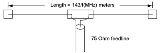
A
dipole antenna is a
radioRadio is the transmission of signals through free space by modulation of electromagnetic waves with frequencies below those of visible light. Electromagnetic radiation travels by means of oscillating electromagnetic fields that pass through the air and the vacuum of space...
antenna that can be made of a simple
wireA wire is a single, usually cylindrical, flexible strand or rod of metal. Wires are used to bear mechanical loads and to carry electricity and telecommunications signals. Wire is commonly formed by drawing the metal through a hole in a die or draw plate. Standard sizes are determined by various...
, with a center-fed
driven elementIn a multielement antenna array , the driven element or active element is the element in the antenna which is electrically connected to the receiver or transmitter. In a transmitting antenna it is driven or excited by the RF current from the transmitter, and is the source of the radio waves...
. It consists of two metal conductors of rod or wire, oriented parallel and
collinearA set of points is collinear if they lie on a single line. Related concepts include:In mathematics:...
with each other (in line with each other), with a small space between them. The
radio frequencyRadio frequency is a rate of oscillation in the range of about 3 kHz to 300 GHz, which corresponds to the frequency of radio waves, and the alternating currents which carry radio signals...
voltage is applied to the antenna at the center, between the two conductors. These antennas are the simplest practical antennas from a theoretical point of view. They are used alone as antennas, notably in traditional "rabbit ears"
television antennaA television antenna, or TV aerial, is an antenna specifically designed for the reception of over the air broadcast television signals, which are transmitted at frequencies from about 41 to 250 MHz in the VHF band, and 470 to 960 MHz in the UHF band in different countries...
s, and as the
driven elementIn a multielement antenna array , the driven element or active element is the element in the antenna which is electrically connected to the receiver or transmitter. In a transmitting antenna it is driven or excited by the RF current from the transmitter, and is the source of the radio waves...
in many other types of antennas, such as the Yagi. Dipole antennas were invented by German physicist Heinrich Hertz around 1886 in his pioneering experiments with
radio waveRadio Wave may refer to:*Radio frequency*Radio Wave 96.5, a radio station in Blackpool, UK...
s.
Elementary doublet
An elementary doublet is a small length of
conductorIn physics and electrical engineering, a conductor is a material which contains movable electric charges. In metallic conductors such as copper or aluminum, the movable charged particles are electrons...

(small compared to the
wavelengthIn physics, the wavelength of a sinusoidal wave is the spatial period of the wave—the distance over which the wave's shape repeats.It is usually determined by considering the distance between consecutive corresponding points of the same phase, such as crests, troughs, or zero crossings, and is a...

) carrying an
alternating currentIn alternating current the movement of electric charge periodically reverses direction. In direct current , the flow of electric charge is only in one direction....
:
Here

is the
angular frequencyIn physics, angular frequency ω is a scalar measure of rotation rate. Angular frequency is the magnitude of the vector quantity angular velocity...
(and

the
frequencyFrequency is the number of occurrences of a repeating event per unit time. It is also referred to as temporal frequency.The period is the duration of one cycle in a repeating event, so the period is the reciprocal of the frequency...
), and

is

, so that

is a
phasorPhasor is a phase vector representing a sine wave.Phasor may also be:* Phasor , a stereo music, sound and speech synthesizer for the Apple II computer* Phasor measurement unit, a device that measures phasors on an electricity grid...
.
Note that this dipole cannot be physically constructed because the current needs somewhere to come from and somewhere to go to. In reality, this small length of conductor will be just one of the multiple segments into which we must divide a real antenna, in order to calculate its properties. The interest of this imaginary elementary antenna is that we can easily calculate the electrical far field of the electromagnetic wave
radiatedIn physics, radiation is a process in which energetic particles or energetic waves travel through a medium or space. There are two distinct types of radiation; ionizing and non-ionizing...
by each elementary doublet. We give just the result:
Where,
The exponent of

accounts for the
phasePhase in waves is the fraction of a wave cycle which has elapsed relative to an arbitrary point.-Formula:The phase of an oscillation or wave refers to a sinusoidal function such as the following:...
dependence of the electrical field on time and the distance from the dipole.
The far electric field

of the electromagnetic wave is coplanar with the conductor and
perpendicularIn geometry, two lines or planes are considered perpendicular to each other if they form congruent adjacent angles . The term may be used as a noun or adjective...
with the line joining the dipole to the point where the field is evaluated. If the dipole is placed in the center of a
sphereA sphere is a perfectly round geometrical object in three-dimensional space, such as the shape of a round ball. Like a circle in two dimensions, a perfect sphere is completely symmetrical around its center, with all points on the surface lying the same distance r from the center point...
in the axis south-north, the electric field would be
parallelParallelism is a term in geometry and in everyday life that refers to a property in Euclidean space of two or more lines or planes, or a combination of these. The assumed existence and properties of parallel lines are the basis of Euclid's parallel postulate. Two lines in a plane that do not...
to geographic
meridiansA meridian is an imaginary line on the Earth's surface from the North Pole to the South Pole that connects all locations along it with a given longitude. The position of a point along the meridian is given by its latitude. Each meridian is perpendicular to all circles of latitude...
and the
magnetic fieldA magnetic field is a mathematical description of the magnetic influence of electric currents and magnetic materials. The magnetic field at any given point is specified by both a direction and a magnitude ; as such it is a vector field.Technically, a magnetic field is a pseudo vector;...
of the electromagnetic wave would be parallel to geographic
parallelsParallels may refer to:* Circle of latitude , imaginary east-west circles connecting all locations that share a given latitude* "Parallels", the third track from the 1977 Yes album Going for the One...
.
Near Field
The above formulas are valid for the far field of the antenna (

), and are the only contribution to the radiated field. The formulas in the near field have additional terms that reduce with

and

. These are,
where

. The energy associated with the term of the near field flows back and forward out and into the antenna.
Short dipole
A short dipole is a physically feasible dipole formed by two conductors with a total length

very small compared with the wavelength

. The two conducting wires are fed at the centre of the dipole. We assume the hypothesis that the current is maximal at the centre (where the dipole is fed) and that it decreases linearly to be zero at the ends of the wires. Note that the direction of the current is the same in both the dipole branches - to the right in both or to the left in both. The far field

of the electromagnetic wave radiated by this dipole is:
Emission is maximal in the plane perpendicular to the dipole and zero in the direction of wires which is the direction of the current. The emission diagram is circular section
torusIn geometry, a torus is a surface of revolution generated by revolving a circle in three dimensional space about an axis coplanar with the circle...
shaped (right image) with zero inner diameter. In the left image the doublet is vertical in the
torusIn geometry, a torus is a surface of revolution generated by revolving a circle in three dimensional space about an axis coplanar with the circle...
centre.
Knowing this electric field, we can compute the total emitted power and then compute the resistive part of the series impedance of this dipole due to the radiated field, known as the
radiation resistanceRadiation resistance is that part of an antenna's feedpoint resistance that is caused by the radiation of electromagnetic waves from the antenna. The radiation resistance is determined by the geometry of the antenna, not by the materials of which it is made...
:
(for
). where

is the impedance of free space. Using a common approximation of

ohms, we get:
ohms
Antenna gain
Antenna gainIn electromagnetics, an antenna's power gain or simply gain is a key performance figure which combines the antenna's directivity and electrical efficiency. As a transmitting antenna, the figure describes how well the antenna converts input power into radio waves headed in a specified direction...
is the ratio of surface power radiated by the antenna to the surface power radiated by a hypothetical isotropic antenna:

The surface power carried by an electromagnetic wave is:

The surface power radiated by an isotropic antenna feed with the same power is:
Substituting values for the case of a short dipole, final result is:
= 1.5 = 1.76 dBi
dBi simply means decibels gain, relative to an
isotropic antenna.
Half-wave antenna

Typically a dipole antenna is formed by two quarter wavelength conductors or elements placed back to back for a total length of

. A standing wave on an element of a length ~

yields the greatest voltage differential, as one end of the element is at a node while the other is at an antinode of the wave. The larger the differential voltage, the greater the current between the elements.
Assuming a sinusoidal distribution, the current impressed by this voltage differential is given by:
For the far-field case, the formula for the electric field of a radiating electromagnetic wave is somewhat more complex:

But the fraction

is not very different from

.
The resulting emission diagram is a slightly flattened
torusIn geometry, a torus is a surface of revolution generated by revolving a circle in three dimensional space about an axis coplanar with the circle...
.
The image on the left shows the section of the emission pattern. We have drawn, in dotted lines, the emission pattern of a short dipole. We can see that the two patterns are very similar. The image at right shows the perspective view of the same emission pattern.
This time it is not possible to compute analytically the total power emitted by the antenna (the last formula does not allow), though a simple numerical integration or series expansion leads to the more precise, actual value of the half-wave resistance:
This leads to the gain of a dipole antenna,

:
-
-

The resistance, however, is not enough to characterize the dipole impedance, as there is also an imaginary part——it is better to measure the impedance.
In the image below, the real and imaginary parts of a dipole's impedance are drawn for lengths going from
to
, accompanied by a chart comparing the gains of dipole antennas of other lengths, both as a number and in dBi:
| Gain of dipole antennas |
length L in  |
Gain |
Gain(dBi) |
0.1 |
1.50 |
1.76 |
| 0.5 |
1.64 |
2.15 |
Quarter-wave antenna
The quarter wave monopoleA monopole antenna is a class of radio antenna consisting of a straight rod-shaped conductor, often mounted perpendicularly over some type of conductive surface, called a ground plane. The driving signal from the transmitter is applied, or for receiving antennas the output voltage is taken,...
antenna is a single element antenna fed at one end, that behaves as a dipole antenna. It is formed by a conductor 
in length. It is fed in the lower end, which is near a conductive surface which works as a reflector (see Effect of ground). The current in the reflected image has the same direction and phase as the current in the real antenna. The quarter-wave conductor and its image together form a half-wave dipole that radiates only in the upper half of space.
In this upper side of space the emitted field has the same amplitude of the field radiated by a half-wave dipole fed with the same current. Therefore, the total emitted power is one-half the emitted power of a half-wave dipole fed with the same current. As the current is the same, the radiation resistance (real part of series impedance) will be one-half of the series impedance of a half-wave dipole. As the reactive part is also divided by 2, the impedance of a quarter wave antenna is
ohms. Since the fields above ground are the same as for the dipole, but only half the power is applied, the gain is twice (3dB over) that for a half-wave dipole (
), that is 5.14 dBi.
The earth can be used as ground plane, but it is a poor conductor: the reflected antenna image is only clear at glancing angles (far from the antenna). At these glancing angles, electromagnetic fields and radiation patterns are thus the same as for a half-wave dipole.
Naturally, the impedance of the earth is far inferior to that of a good conductor ground plane -- this can be improved (at cost) by laying a copper mesh.
When ground is not available (such as in a vehicle) other metallic surfaces can serve as a ground plane (typically the vehicle's roof). Alternatively, radial wires placed at the base of the antenna can simulate a ground plane. For VHF bands, the radiating and ground-plane elements can be constructed from rigid rods or tubes.
Frequency versus length
Dipoles that are much smaller than the wavelength of the signal are called Hertzian, short, or infinitesimal dipoles. These have a very low radiation resistanceRadiation resistance is that part of an antenna's feedpoint resistance that is caused by the radiation of electromagnetic waves from the antenna. The radiation resistance is determined by the geometry of the antenna, not by the materials of which it is made...
and a high reactance, making them inefficient, but they are often the only available antennas at very long wavelengths. Dipoles whose length is half the wavelength of the signal are called half-wave dipoles, and are more efficient. In general radio engineering, the term dipole usually means a half-wave dipole (center-fed).
A half-wave dipole is cut to length
for frequency
MHz according to the formula
where
is in metres or
where
is in feetThe foot is an anatomical structure found in many vertebrates. It is the terminal portion of a limb which bears weight and allows locomotion. In many animals with feet, the foot is a separate organ at the terminal part of the leg made up of one or more segments or bones, generally including claws...
. This is because the impedance of the dipole is purely resistive at about this length. The length of the dipole antenna is approximately 95% of half a wavelength at the speed of light in free space. The exact value depends on the ratio of the wire radius to wavelength, as the reactance of a dipole depends on the ratio of wire radius to wavelength. For thin wires (radius = 0.000001 wavelengths, this is approximately 98.1%, dropping to 91.5% for thick wires (radius = 0.01 wavelengths).
The magic numbers above are derived from a one Hz wavelength which is the distance that light radio travels in one second. Speed of lightThe speed of light in vacuum, usually denoted by c, is a physical constant important in many areas of physics. Its value is 299,792,458 metres per second, a figure that is exact since the length of the metre is defined from this constant and the international standard for time...
in vacuum is 299,792,458 m/s, which is divided by 1 million to account for MHz rather than Hz, which is then divided by 2 for a half-wave dipole antenna. A fudge factorA fudge factor is a quantity introduced into a calculation in order to "fudge" the results: that is, either to make them match better what happens in the real world, or to add an error margin...
of approximately 0.95 is multiplied to account for the fact the input reactance of a dipole is inductive when exactly 0.5 wavelengths long, but the reactance reduces to 0 (i.e. the dipole becomes resonanate) at a length of approximately 0.475 wavelengths, which results in the magic number of 143 m·MHz or 468 ft·MHz. But as noted above, a more accurate calculation would need to take into account the wire radius. Such a calculation is quite complex.
Radiation pattern and gain
Dipoles have an radiation patternIn the field of antenna design the term radiation pattern most commonly refers to the directional dependence of the strength of the radio waves from the antenna or other source ....
, shaped like a toroidToroid may refer to*Toroid , a doughnut-like solid whose surface is a torus.*Toroidal inductors and transformers which have wire windings on circular ring shaped magnetic cores.*Vortex ring, a toroidal flow in fluid mechanics....
(doughnut) symmetrical about the axis of the dipole. The radiation is maximum at right angles to the dipole, dropping off to zero on the antenna's axis. The theoretical maximum gain of a Hertzian dipole is 10 log 1.5 or 1.76 dBi. The maximum theoretical gain of a λ/2-dipole is 10 log 1.64 or 2.15 dBi.
Feeder line
Ideally, a half-wave (λ/2) dipole should be fed with a balanced line matching the theoretical 73 ohm impedance of the antenna. A folded dipole uses a 300 ohm balanced feeder line.
Many people have had success in feeding a dipole directly with a coaxial cable feed rather than a ladder-line. However, coax is not symmetrical and thus not a balanced feeder. It is unbalanced, because the outer shield is connected to earth potential at the other end. When a balanced antenna such as a dipole is fed with an unbalanced feeder, common mode currents can cause the coax line to radiate in addition to the antenna itself, and the radiation pattern may be asymmetrically distorted. This can be remedied with the use of a balunA balun is a type of electrical transformer that can convert electrical signals that are balanced about ground to signals that are unbalanced , and the reverse. They are also often used to connect lines of differing impedance...
.
Set-top TV antenna
The most common dipole antenna is the type used with televisionTelevision is a telecommunication medium for transmitting and receiving moving images that can be monochrome or colored, with accompanying sound...
s, often colloquially referred to as "rabbit ears" or "bunny ears". While in most applications the dipole elements are arranged along the same line, rabbit ears are adjustable in length and angle. Larger dipoles are sometimes hung in a V shape with the center near the radio equipment on the ground or the ends on the ground with the center supported. Shorter dipoles can be hung vertically.
Some have extra elements to get better reception such as loops (especially for UHF transmissions), which can be turnable around a vertical axis, or a dial, which modifies the electrical properties of the antenna at each dial position.
Folded dipole
Another common place one can see dipoles is as antennas for the FM band - these are folded dipoles. The tips of the antenna are folded back until they almost meet at the feedpoint, such that the antenna comprises one entire wavelength. This arrangement has a greater bandwidth than a standard half-wave dipole. If the conductor has a constant radius and cross-section, at resonance the input impedance is four times that of a half-wave dipole.
Shortwave antenna
Dipoles for longer wavelengths are made from solid or stranded wire. Portable dipole antennas are made from wire that can be rolled up when not in use. Ropes with weights on the ends can be thrown over supports such as tree branches and then used to hoist up the antenna. The center and the connecting cable can be hoisted up with the ends on the ground or the ends hoisted up between two supports in a V shape. While permanent antennas can be trimmed to the proper length, it is helpful if portable antennas are adjustable to allow for local conditions when moved. One easy way is to fold the ends of the elements to form loops and use adjustable clamps. The loops can then be used as attachment points.
It is important to fit a good insulator at the ends of the dipole, as failure to do so can lead to a flashoverA flashover is the near simultaneous ignition of most of the directly exposed combustible material in an enclosed area. When certain organic materials are heated they undergo thermal decomposition and release flammable gases...
if the dipole is used with a transmitter. Various purchased or improvised insulators can be used.
Whip antenna
The whip antennaA whip antenna is an antenna consisting of a single straight flexible wire or rod, often mounted above some type of conducting surface called a ground plane. The bottom end of the whip is connected to the radio receiver or transmitter. They are designed to be flexible so that they won't break...
is probably the most common and simplest-looking antenna. These are monopoles, and the most common and practical is the quarter-wave monopole which could be considered as half of a dipole using a ground plane as the image of the other half. The commonly referred-to end-fed dipole is actually just a half-wave monopole whip antenna.
Dipoles versus whip antennas
Dipoles are generally more efficient than whip antennas (quarter-wave monopoles). The total radiated power and the radiation resistance are twice that of a quarter-wave monopole. Thus, if a whip antenna were used with an infinite perfectly conducting ground planeIn electrical engineering, a ground plane is an electrically conductive surface.-Radio antenna theory :In telecommunication, a ground plane structure or relationship exists between the antenna and another object, where the only structure of the object is a structure which permits the antenna to...
, then it would be as efficient in half-space as a dipole in free space an infinite distance from any conductive surfaces such as the earthIn electrical engineering, ground or earth may be the reference point in an electrical circuit from which other voltages are measured, or a common return path for electric current, or a direct physical connection to the Earth....
's surface.
Dipole towers
Large constructed half-wavelength dipole towers include the Warsaw radio mastThe Warsaw radio mast was the world's tallest structure until its collapse on 8 August 1991. It is the second tallest land-based structure ever built, being surpassed as tallest by the Burj Khalifa, completed in 2010....
— the only half-wave dipole for longwaveIn radio, longwave refers to parts of radio spectrum with relatively long wavelengths. The term is a historic one dating from the early 20th century, when the radio spectrum was considered to consist of long, medium and short wavelengths...
ever built — and Blaw-Knox TowerThe Blaw-Knox company was a manufacturer of steel structures and construction equipment based in Pittsburgh, Pennsylvania. The company is today best known for its radio towers, most of which were constructed during the 1930s in the United States...
s.
Military
US Military personnel occasionally use a 'doublet' antenna, especially during dismounted unconventional warfareUnconventional warfare is the opposite of conventional warfare. Where conventional warfare is used to reduce an opponent's military capability, unconventional warfare is an attempt to achieve military victory through acquiescence, capitulation, or clandestine support for one side of an existing...
. A radio operator may choose to bring several doublet antennas for different frequencies, such as an antenna cut to length for the set MEDEVAC (medical evacuation) frequency, NCS (net control station) frequency, and tactical frequency (the frequency used by troops in the field). This approach may not be acceptable depending on the mission. Note that a doublet antenna will not work with the standard SINCGARSSINCGARS is a Combat Net Radio currently used by U.S. and allied military forces. The radios, which handle voice and data communications, are designed to be reliable, secure and easily maintained...
radio when using frequency hopping(FH) but is effective for single channel (SC). A doublet antenna is more practical for radios not intended for FH.
Collinear antenna systems based on dipoles
Dipoles can be stacked end to end in phased arrays to make collinear antenna arrayIn telecommunications, a collinear antenna array is an array of dipole antennas mounted in such a manner that the corresponding elements of each antenna are parallel and collinear, that is they are located along a common line or axis....
s, which exhibit more gain in certain directions—the toroidal radiation pattern is flattened out, giving maximum gain at right angles to the axis of the colinear array.
Slim Jim or J-Pole
A Slim Jim or J-pole is a form of end-fed dipole connected to a quarter-wave stub matching section.
Ideal half-wavelength dipole
This type of antenna is a special case where each wire is exactly one-quarter of the wavelength, for a total of a half wavelength. The radiation resistanceRadiation resistance is that part of an antenna's feedpoint resistance that is caused by the radiation of electromagnetic waves from the antenna. The radiation resistance is determined by the geometry of the antenna, not by the materials of which it is made...
is about 73 ohms if wire diameter is ignored, making it easily matched to a coaxial transmission line. The directivityIn electromagnetics, directivity is a figure of merit for an antenna. It measures the power density the antenna radiates in the direction of its strongest emission, versus the power density radiated by an ideal isotropic radiator radiating the same total power.An antenna's directivity is a...
is a constant 1.64, or 2.15 dB. Actual gain will be a little less due to ohmic losses.
If the dipole is not driven at the centre then the feed point resistance will be higher. If the feed point is distance x from one end of a half wave (λ/2) dipole, the resistance will be described by the following equation.

If taken to the extreme then the feed point resistance of a λ/2 long rod is infinite, but it is possible to use a λ/2 pole as an aerial; the right way to drive it is to connect it to one terminal of a parallel LC resonant circuit. The other side of the circuit must be connected to the braid of a coaxial cableCoaxial cable, or coax, has an inner conductor surrounded by a flexible, tubular insulating layer, surrounded by a tubular conducting shield. The term coaxial comes from the inner conductor and the outer shield sharing the same geometric axis...
lead and the core of the coaxialIn geometry, coaxial means that two or more forms share a common axis; it is the three-dimensional linear analogue of concentric.Coaxial cable, as a common example, has a wire conductor in the centre a circumferential outer conductor and an insulating medium called the dielectric separating...
cable can be connected part way up the coil from the RF ground side. An alternative means of feeding this system is to use a second coil which is magnetically coupled to the coilA coil is a series of loops. A coiled coil is a structure in which the coil itself is in turn also looping.-Electromagnetic coils:An electromagnetic coil is formed when a conductor is wound around a core or form to create an inductor or electromagnet...
attached to the aerial.
Folded dipole
A folded dipole is a half-wave dipole with an additional wire connecting its two ends. If the additional wire has the same diameter and cross-section as the dipole, two nearly identical radiating currents are generated. The resulting far-field emission pattern is nearly identical to the one for the single-wire dipole described above; however, at resonance its input (feedpoint) impedance
is four times the radiation resistance of a single-wire dipole. This is because for a fixed amount of power, the total radiating current
is equal to twice the current in each wire and thus equal to twice the current at the feed point. Equating the average radiated power to the average power delivered at the feedpoint, we may write

It follows that

The folded dipole is therefore well matched to 300-Ohm balanced transmission lines.
Hertzian dipole (current element)
The Hertzian dipole is a theoretical short dipole (significantly smaller than the wavelength) with a uniform current along its length. A true Hertzian dipole cannot physically exist, since the assumed current distribution implies an infinite charge density at its ends, and significant radiation requires a very high current over its very short length.
The radiation resistance is given by:

where
is the impedance of free space. This is precisely four times the radiation resistance of the real short dipole with the linearly tapered current distribution.
The radiation resistance is typically a fraction of an ohm, making a real infinitesimal dipole an inefficient radiator. The directivity D, which is the theoretical gain of the antenna assuming no ohmic losses (not real-world), is a constant of 1.5, which corresponds to 1.76 dB. Actual gain will be much less due to the ohmic losses (because of the very high currents) and the loss inherent in connecting a transmission line to the antenna, which is very hard to do efficiently considering the incredibly low radiation resistance. The maximum effective apertureIn electromagnetics and antenna theory, antenna aperture or effective area is a measure of how effective an antenna is at receiving the power of radio waves. The aperture is defined as the area, oriented perpendicular to the direction of an incoming radio wave, which would intercept the same...
is:

or

A surprising result is that even though the Hertzian dipole is minute, its effective aperture is comparable to antennas many times its size. A real small antenna will have a smaller effective aperture, because of its lower gain.
Dipole as a reference standard
Antenna gainIn electronics, gain is a measure of the ability of a circuit to increase the power or amplitude of a signal from the input to the output. It is usually defined as the mean ratio of the signal output of a system to the signal input of the same system. It may also be defined on a logarithmic scale,...
is sometimes measured as "x dB above a dipole", which means that the antenna in question is being compared to a dipole, and has x dB more gain (has more directivity) than the dipole tuned to the same operating frequencyFrequency is the number of occurrences of a repeating event per unit time. It is also referred to as temporal frequency.The period is the duration of one cycle in a repeating event, so the period is the reciprocal of the frequency...
. In this case one says the antenna has a gainIn electronics, gain is a measure of the ability of a circuit to increase the power or amplitude of a signal from the input to the output. It is usually defined as the mean ratio of the signal output of a system to the signal input of the same system. It may also be defined on a logarithmic scale,...
of "x dBd" (see decibelThe decibel is a logarithmic unit that indicates the ratio of a physical quantity relative to a specified or implied reference level. A ratio in decibels is ten times the logarithm to base 10 of the ratio of two power quantities...
). More often, gains are expressed relative to an isotropic radiatorAn isotropic radiator is a theoretical point source of electromagnetic or sound waves which radiates the same intensity of radiation in all directions. It has no preferred direction of radiation. It radiates uniformly in all directions over a sphere centred on the source...
, which is an imaginary aerial that radiates equally in all directions. In this case one uses dBi instead of dBd (see decibelThe decibel is a logarithmic unit that indicates the ratio of a physical quantity relative to a specified or implied reference level. A ratio in decibels is ten times the logarithm to base 10 of the ratio of two power quantities...
). As it is impossible to build an isotropic radiator, gain measurements expressed relative to a dipole are more practical when a reference dipole aerial is used for experimental measurements. 0 dBd is often considered equal to 2.15 dBi.
From Babinet's principleIn physics, Babinet's principle is a theorem concerning diffraction that states that the diffraction pattern from an opaque body is identical to that from a hole of the same size and shape except for the overall forward beam intensity.-Explanation:...
, a dipole antenna is complementary to a slot antennaA slot antenna consists of a metal surface, usually a flat plate, with a hole or slot cut out. When the plate is driven as an antenna by a driving frequency, the slot radiates electromagnetic waves in similar way to a dipole antenna. The shape and size of the slot, as well as the driving frequency,...
consisting of a slot the same size and shape as a dipole cut from an infinite sheet of metal; both give the same radiation pattern.
Dipole with baluns
A dipole, being composed of two symmetrical ungrounded elements, works best when fed by a balanced transmission lineIn communications and electronic engineering, a transmission line is a specialized cable designed to carry alternating current of radio frequency, that is, currents with a frequency high enough that its wave nature must be taken into account...
, such as ladder line. When a dipole with an unbalanced feedline such as coaxial cableCoaxial cable, or coax, has an inner conductor surrounded by a flexible, tubular insulating layer, surrounded by a tubular conducting shield. The term coaxial comes from the inner conductor and the outer shield sharing the same geometric axis...
is used for transmittingTransmission, in telecommunications, is the process of sending, propagating and receiving an analogue or digital information signal over a physical point-to-point or point-to-multipoint transmission medium, either wired, optical fiber or wireless...
, the shield side of the cable, in addition to the antenna, radiates. This can induce RFRadio frequency is a rate of oscillation in the range of about 3 kHz to 300 GHz, which corresponds to the frequency of radio waves, and the alternating currents which carry radio signals...
currents into other electronic equipment near the radiating feedline, causing RF interference. Furthermore, the antenna is not as efficient as it could be because it is radiating closer to the ground and its radiation (and reception) pattern may be distorted asymmetrically. At higher frequencies, where the length of the dipole becomes significantly shorter than the diameter of the feeder coax, this becomes a more significant problem. To prevent this, dipoles fed by coaxial cables have a balunA balun is a type of electrical transformer that can convert electrical signals that are balanced about ground to signals that are unbalanced , and the reverse. They are also often used to connect lines of differing impedance...
between the cable and the antenna, to convert the unbalanced signal provided by the coax to a balanced symmetrical signal for the antenna.
Several types of baluns are commonly used to transmit on a dipole: current baluns and coax baluns.
Current balun
A current balun is a bit more expensive but has the characteristic of being more broadband.http://www.arising.com.au/people/Holland/Ralph/CMBalun.htm
It can also be as simple as winding the coax cable over a ferrite core.http://www.northcountryradio.com/Articles/fmdip.htm Or nothing but coax cable:http://www.ham-radio.com/k6sti/balun.htm
Coax balun
A coax balun is a cost effective method to eliminate feeder radiation, but is limited to a narrow set of operating frequencies.
- One easy way to make a balun is a (λ/2) length of coaxial cable. The inner core of the cable is linked at each end to one of the balanced connections for a feeder or dipole. One of these terminals should be connected to the inner core of the coaxial feeder. All three braids should be connected together. This then forms a 4:1 balun which works correctly at only a narrow band of frequencies.
Sleeve balun
At VHF frequencies, a sleeve balun can also be built to remove feeder radiation.
- Another narrow band design is to use a λ/4 length of metal pipe. The coaxial cable is placed inside the pipe; at one end the braid is wired to the pipe while at the other end no connection is made to the pipe. The balanced end of this balun is at the end where the pipe is wired to the braid. The λ/4 conductor acts as a transformer converting the infinite impedance at the unconnected end into a zero impedance at the end connected to the braid. Hence any current entering the balun through the connection, which goes to the braid at the end with the connection to the pipe, will flow into the pipe. This balun design is impractical for low frequencies because of the long length of pipe that will be needed.
See also
- Electronic symbol
- isotropic antenna
- omnidirectional antenna
In radio communication, an omnidirectional antenna is an antenna which radiates radio wave power uniformly in all directions in one plane, with the radiated power decreasing with elevation angle above or below the plane, dropping to zero on the antenna's axis. This radiation pattern is often...
- whip antenna
A whip antenna is an antenna consisting of a single straight flexible wire or rod, often mounted above some type of conducting surface called a ground plane. The bottom end of the whip is connected to the radio receiver or transmitter. They are designed to be flexible so that they won't break...
- driven element
In a multielement antenna array , the driven element or active element is the element in the antenna which is electrically connected to the receiver or transmitter. In a transmitting antenna it is driven or excited by the RF current from the transmitter, and is the source of the radio waves...
- balun
A balun is a type of electrical transformer that can convert electrical signals that are balanced about ground to signals that are unbalanced , and the reverse. They are also often used to connect lines of differing impedance...
- Coaxial antenna
A coaxial antenna is a particular form of a half-wave dipole antenna, most often employed as a vertically polarized omnidirectional antenna.-History:Arnold B...
- amateur radio
Amateur radio is the use of designated radio frequency spectrum for purposes of private recreation, non-commercial exchange of messages, wireless experimentation, self-training, and emergency communication...
- shortwave listening
Shortwave listening is the hobby of listening to shortwave radio broadcasts located on frequencies between 1700 kHz and 30 MHz. Listeners range from casual users seeking international news and entertainment programming to hobbyists immersed in the technical aspects of radio reception and DXing...
- T-aerial
A T-aerial is an antenna used for VLF, LF, MF and shortwave transmission or reception.It consists of a horizontal wire suspended between two radio masts or towers. A vertical wire is connected to the middle of the horizontal wire and hangs down close to the ground, where it is connected to the...
- AM broadcasting
AM broadcasting is the process of radio broadcasting using amplitude modulation. AM was the first method of impressing sound on a radio signal and is still widely used today. Commercial and public AM broadcasting is carried out in the medium wave band world wide, and on long wave and short wave...
- FM broadcasting
FM broadcasting is a broadcasting technology pioneered by Edwin Howard Armstrong which uses frequency modulation to provide high-fidelity sound over broadcast radio. The term "FM band" describes the "frequency band in which FM is used for broadcasting"...
External links