
Cascode
Encyclopedia
The cascode is a two-stage amplifier
composed of a transconductance
amplifier followed by a current buffer
. Compared to a single amplifier stage, this combination may have one or more of the following characteristics: higher input-output isolation, higher input impedance
, high output impedance
, higher gain
or higher bandwidth.
In modern circuits, the cascode is often constructed from two transistor
s (BJT
s or FET
s), with one operating as a common emitter
or common source
and the other as a common base
or common gate
.
The cascode improves input-output isolation (or reverse transmission) as there is no direct coupling from the output to input. This eliminates the Miller effect
and thus contributes to a much higher bandwidth.
s and transistor
s. The word "cascode" is a contraction of the phrase "cascade to cathode". It was first used in an article by F.V. Hunt and R.W. Hickman in 1939, in a discussion for application in low-voltage stabilizers. They proposed a cascode of two triode
s (first one with common cathode
, the second one with common grid
) as a replacement for a pentode
.
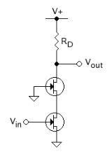
 Figure 1 shows an example of cascode amplifier with a common source
amplifier as input stage driven by signal source Vin. This input stage drives a common gate
amplifier as output stage, with output signal Vout.
The major advantage of this circuit arrangement stems from the placement of the upper field-effect transistor
(FET) as the load of the input (lower) FET's output terminal (drain). Because at operating frequencies the upper FET's gate is effectively grounded, the upper FET's source voltage (and therefore the input transistor's drain) is held at nearly constant voltage during operation. In other words, the upper FET exhibits a low input resistance to the lower FET, making the voltage gain of the lower FET very small, which dramatically reduces the Miller
feedback capacitance from the lower FET's drain to gate. This loss of voltage gain is recovered by the upper FET. Thus, the upper transistor permits the lower FET to operate with minimum negative (Miller) feedback, improving its bandwidth.
The upper FET gate is electrically grounded, so charge and discharge of stray capacitance Cdg between drain and gate is simply through RD and the output load (say Rout), and the frequency response is affected only for frequencies above the associated RC time constant
: τ = Cdg RD//Rout, namely f = 1/(2πτ), a rather high frequency because Cdg is small. That is, the upper FET gate does not suffer from Miller amplification of Cdg.
If the upper FET stage were operated alone using its source as input node (i.e. common-gate (CG) configuration), it would have good voltage gain and wide bandwidth. However, its low input impedance would limit its usefulness to very low impedance voltage drivers. Adding the lower FET results in a high input impedance, allowing the cascode stage to be driven by a high impedance source.
If one were to replace the upper FET with a typical inductive/resistive load, and take the output from the input transistor's drain (i.e. a common-source(CS) configuration), the CS configuration would offer the same input impedance as the cascode, but the cascode configuration would offer a potentially greater gain and much greater bandwidth.
The cascode circuit can also be built using bipolar transistors, or MOSFETs, or even one FET (or MOSFET) and one BJT. In the latter case, the BJT must be the upper transistor; otherwise, the (lower) BJT will always saturate (unless extraordinary steps are taken to bias it).
often functions as a "one-transistor" cascode. Common in the front ends of sensitive VHF
receivers, a dual-gate MOSFET is operated as a common-source amplifier with the primary gate (usually designated "gate 1" by MOSFET manufacturers) connected to the input and the 2nd gate grounded (bypassed). Internally, there is one channel covered by the two adjacent gates; therefore, the resulting circuit is electrically a cascode composed of two FETs, the common lower-drain-to-upper-source connection merely being that portion of the single channel that lies physically adjacent to the border between the two gates.
circuit in superheterodyne receivers. At the lower gate the RF signal is fed to the mixer and at the upper gate the local oscillator
signal is fed to the mixer. Both signals are multiplied by the mixer and the difference frequency, the Intermediate frequency
is taken from the upper drain of the cascode mixer.
s, transistors have become cheap in terms of silicon die area. In MOSFET
technology especially, cascoding can be used in current mirror
s to increase the output impedance of the output current source
.
A modified version of the cascode can also be used as a modulator
, particularly for amplitude modulation
. The upper device supplies the audio signal, and the lower is the RF
amplifier device.
) by using its input impedance
, output impedance
, and voltage gain
. These parameters are related to the corresponding g-parameters below. Other useful properties not considered here are circuit bandwidth and dynamic range.
BJT Cascode: low-frequency small-signal parameters
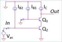 The idealized small-signal equivalent circuit can be constructed for the circuit in figure 2 by replacing the current sources with open-circuits and the capacitors with short circuits, assuming they are large enough to act as short-circuits at the frequencies of interest. The BJTs can be represented in the small-signal circuit by the hybrid-pi model
.
MOSFET Cascode: low-frequency small-signal parameters
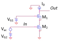 Similarly, the small-signal parameters can be derived for the MOSFET version, also replacing the MOSFET by its hybrid-pi model equivalent. This derivation can be simplified by noting that the MOSFET gate current is zero, so the small-signal model for the BJT becomes that of the MOSFET in the limit of zero base current:
where VT is the thermal voltage.
The combination of factors gmrO occurs often in the above formulas, inviting further examination. For the bipolar transistor this product is (see hybrid-pi model
):
In a typical discrete bipolar device the Early voltage VA ≈ 100 V and the thermal voltage near room temperature is VT ≈ 25 mV, making gmrO ≈ 4000, a rather large number. From the article on hybrid-pi model
, we find for the MOSFET in the active mode:
At the 65 nanometer
technology node, ID ≈ 1.2 mA/μ of width, supply voltage is VDD = 1.1 V; Vth ≈ 165 mV, and Vov = VGS-Vth ≈ 5%VDD ≈ 55 mV. Taking a typical length as twice the minimum, L = 2 Lmin = 0.130 μm and a typical value of λ ≈ 1/(4 V/μm L), we find 1/λ ≈ 2 V, and gmrO ≈ 110, still a large value.
The point is that because gmrO is large almost regardless of the technology, the tabulated gain and the output resistance for both the MOSFET and the bipolar cascode are very large. That fact has implications in the discussion that follows.
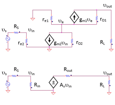 The g-parameters found in the above formulas can be used to construct a small-signal voltage amplifier with the same gain, input and output resistance as the original cascode (an equivalent circuit
). This circuit applies only at frequencies low enough that the transistor parasitic capacitances do not matter. The figure shows the original cascode (Fig. 1) and the equivalent voltage amplifier or g-equivalent two-port (Fig. 4). The equivalent circuit allows easier calculations of the behavior of the circuit for different drivers and loads. In the figure a Thévenin equivalent voltage source with Thévenin resistance RS drives the amplifier, and at the output a simple load resistor RL is attached. Using the equivalent circuit, the input voltage to the amplifier is (see article on voltage division):
which shows the importance of using a driver with resistance RS << Rin to avoid attenuation of the signal entering the amplifier. From the above amplifier characteristics, we see that Rin is infinite for the MOSFET cascode, so no attenuation of input signal occurs in that case. The BJT cascode is more restrictive because Rin = rπ2.
In a similar fashion, the output signal from the equivalent circuit is
In low frequency circuits, a high voltage gain is typically desired, hence the importance of using a load with resistance RL >> Rout to avoid attenuation of the signal reaching the load. The formulas for Rout can be used either to design an amplifier with a sufficiently small output resistance compared to the load or, if that cannot be done, to decide upon a modified circuit, for example, to add a voltage follower that matches the load better.
The earlier estimate showed that the cascode output resistance is very large. The implication is that many load resistances will not satisfy the condition RL >> Rout (an important exception is driving a MOSFET as load, which has infinite low frequency input impedance). However, the failure to satisfy the condition RL >> Rout is not catastrophic because the cascode gain also is very large. If the designer is willing, the large gain can be sacrificed to allow a low load resistance; for RL << Rout the gain simplifies as follows:
This gain is the same as that for the input transistor acting alone. Thus, even sacrificing gain, the cascode produces the same gain as the single-transistor transconductance amplifier, but with wider bandwidth.
Because the amplifiers are wide bandwidth, the same approach can determine the bandwidth of the circuit when a load capacitor is attached (with or without a load resistor). The assumption needed is that the load capacitance is large enough that it controls the frequency dependence, and bandwidth is not controlled by the neglected parasitic capacitances of the transistors themselves.
at the input and output of the amplifier is typically desired in order to eliminate signal reflections and maximize power gain
. In the cascode, the isolation between the input and output ports still is characterized by a small reverse transmission term g12, making it easier to design matching networks because the amplifier is approximately unilateral.
Amplifier
Generally, an amplifier or simply amp, is a device for increasing the power of a signal.In popular use, the term usually describes an electronic amplifier, in which the input "signal" is usually a voltage or a current. In audio applications, amplifiers drive the loudspeakers used in PA systems to...
composed of a transconductance
Transconductance
Transconductance, also known as mutual conductance, is a property of certain electronic components. Conductance is the reciprocal of resistance; transconductance, meanwhile, is the ratio of the current change at the output port to the voltage change at the input port. It is written as gm...
amplifier followed by a current buffer
Buffer amplifier
A buffer amplifier is one that provides electrical impedance transformation from one circuit to another...
. Compared to a single amplifier stage, this combination may have one or more of the following characteristics: higher input-output isolation, higher input impedance
Input impedance
The input impedance of an electrical network is the equivalent impedance "seen" by a power source connected to that network. If the source provides known voltage and current, such impedance can be calculated using Ohm's Law...
, high output impedance
Output impedance
The output impedance, source impedance, or internal impedance of an electronic device is the opposition exhibited by its output terminals to an alternating current of a particular frequency as a result of resistance, inductance and capacitance...
, higher gain
Gain
In electronics, gain is a measure of the ability of a circuit to increase the power or amplitude of a signal from the input to the output. It is usually defined as the mean ratio of the signal output of a system to the signal input of the same system. It may also be defined on a logarithmic scale,...
or higher bandwidth.
In modern circuits, the cascode is often constructed from two transistor
Transistor
A transistor is a semiconductor device used to amplify and switch electronic signals and power. It is composed of a semiconductor material with at least three terminals for connection to an external circuit. A voltage or current applied to one pair of the transistor's terminals changes the current...
s (BJT
Bipolar junction transistor
|- align = "center"| || PNP|- align = "center"| || NPNA bipolar transistor is a three-terminal electronic device constructed of doped semiconductor material and may be used in amplifying or switching applications. Bipolar transistors are so named because their operation involves both electrons...
s or FET
Field-effect transistor
The field-effect transistor is a transistor that relies on an electric field to control the shape and hence the conductivity of a channel of one type of charge carrier in a semiconductor material. FETs are sometimes called unipolar transistors to contrast their single-carrier-type operation with...
s), with one operating as a common emitter
Common emitter
In electronics, a common-emitter amplifier is one of three basic single-stage bipolar-junction-transistor amplifier topologies, typically used as a voltage amplifier...
or common source
Common source
In electronics, a common-source amplifier is one of three basic single-stage field-effect transistor amplifier topologies, typically used as a voltage or transconductance amplifier. The easiest way to tell if a FET is common source, common drain, or common gate is to examine where the signal...
and the other as a common base
Common base
In electronics, a common-base amplifier is one of three basic single-stage bipolar junction transistor amplifier topologies, typically used as a current buffer or voltage amplifier...
or common gate
Common gate
In electronics, a common-gate amplifier is one of three basic single-stage field-effect transistor amplifier topologies, typically used as a current buffer or voltage amplifier...
.
The cascode improves input-output isolation (or reverse transmission) as there is no direct coupling from the output to input. This eliminates the Miller effect
Miller effect
In electronics, the Miller effect accounts for the increase in the equivalent input capacitance of an inverting voltage amplifier due to amplification of the effect of capacitance between the input and output terminals...
and thus contributes to a much higher bandwidth.
History
The use of a cascode (sometimes verbified to cascoding) is a common technique for improving analog circuit performance, applicable to both vacuum tubeVacuum tube
In electronics, a vacuum tube, electron tube , or thermionic valve , reduced to simply "tube" or "valve" in everyday parlance, is a device that relies on the flow of electric current through a vacuum...
s and transistor
Transistor
A transistor is a semiconductor device used to amplify and switch electronic signals and power. It is composed of a semiconductor material with at least three terminals for connection to an external circuit. A voltage or current applied to one pair of the transistor's terminals changes the current...
s. The word "cascode" is a contraction of the phrase "cascade to cathode". It was first used in an article by F.V. Hunt and R.W. Hickman in 1939, in a discussion for application in low-voltage stabilizers. They proposed a cascode of two triode
Triode
A triode is an electronic amplification device having three active electrodes. The term most commonly applies to a vacuum tube with three elements: the filament or cathode, the grid, and the plate or anode. The triode vacuum tube was the first electronic amplification device...
s (first one with common cathode
Cathode
A cathode is an electrode through which electric current flows out of a polarized electrical device. Mnemonic: CCD .Cathode polarity is not always negative...
, the second one with common grid
Control grid
The control grid is an electrode used in thermionic valves used to modulate the flow of electrons in the cathode to anode or plate circuit.- Operation :...
) as a replacement for a pentode
Pentode
A pentode is an electronic device having five active electrodes. The term most commonly applies to a three-grid vacuum tube , which was invented by the Dutchman Bernhard D.H. Tellegen in 1926...
.
Operation
Common source
In electronics, a common-source amplifier is one of three basic single-stage field-effect transistor amplifier topologies, typically used as a voltage or transconductance amplifier. The easiest way to tell if a FET is common source, common drain, or common gate is to examine where the signal...
amplifier as input stage driven by signal source Vin. This input stage drives a common gate
Common gate
In electronics, a common-gate amplifier is one of three basic single-stage field-effect transistor amplifier topologies, typically used as a current buffer or voltage amplifier...
amplifier as output stage, with output signal Vout.
The major advantage of this circuit arrangement stems from the placement of the upper field-effect transistor
Field-effect transistor
The field-effect transistor is a transistor that relies on an electric field to control the shape and hence the conductivity of a channel of one type of charge carrier in a semiconductor material. FETs are sometimes called unipolar transistors to contrast their single-carrier-type operation with...
(FET) as the load of the input (lower) FET's output terminal (drain). Because at operating frequencies the upper FET's gate is effectively grounded, the upper FET's source voltage (and therefore the input transistor's drain) is held at nearly constant voltage during operation. In other words, the upper FET exhibits a low input resistance to the lower FET, making the voltage gain of the lower FET very small, which dramatically reduces the Miller
Miller effect
In electronics, the Miller effect accounts for the increase in the equivalent input capacitance of an inverting voltage amplifier due to amplification of the effect of capacitance between the input and output terminals...
feedback capacitance from the lower FET's drain to gate. This loss of voltage gain is recovered by the upper FET. Thus, the upper transistor permits the lower FET to operate with minimum negative (Miller) feedback, improving its bandwidth.
The upper FET gate is electrically grounded, so charge and discharge of stray capacitance Cdg between drain and gate is simply through RD and the output load (say Rout), and the frequency response is affected only for frequencies above the associated RC time constant
RC time constant
In an RC circuit, the value of the time constant is equal to the product of the circuit resistance and the circuit capacitance , i.e. \tau = R × C. It is the time required to charge the capacitor, through the resistor, to 63.2 percent of full charge; or to discharge it to 36.8 percent of its...
: τ = Cdg RD//Rout, namely f = 1/(2πτ), a rather high frequency because Cdg is small. That is, the upper FET gate does not suffer from Miller amplification of Cdg.
If the upper FET stage were operated alone using its source as input node (i.e. common-gate (CG) configuration), it would have good voltage gain and wide bandwidth. However, its low input impedance would limit its usefulness to very low impedance voltage drivers. Adding the lower FET results in a high input impedance, allowing the cascode stage to be driven by a high impedance source.
If one were to replace the upper FET with a typical inductive/resistive load, and take the output from the input transistor's drain (i.e. a common-source(CS) configuration), the CS configuration would offer the same input impedance as the cascode, but the cascode configuration would offer a potentially greater gain and much greater bandwidth.
Stability
The cascode arrangement is also very stable. Its output is effectively isolated from the input both electrically and physically. The lower transistor has nearly constant voltage at both drain and source and thus there is essentially "nothing" to feed back into its gate. The upper transistor has nearly constant voltage at its gate and source. Thus, the only nodes with significant voltage on them are the input and output, and these are separated by the central connection of nearly constant voltage and by the physical distance of two transistors. Thus in practice there is little feedback from the output to the input. Metal shielding is both effective and easy to provide between the two transistors for even greater isolation when required. This would be difficult in one-transistor amplifier circuits, which at high frequencies would require neutralization.Biasing
As shown, the cascode circuit using two "stacked" FET's imposes some restrictions on the two FET's—namely, the upper FET must be biased so its source voltage is high enough (the lower FET drain voltage may swing too low, causing it to make saturation). Insurance of this condition for FET's requires careful selection for the pair, or special biasing of the upper FET gate, increasing cost.The cascode circuit can also be built using bipolar transistors, or MOSFETs, or even one FET (or MOSFET) and one BJT. In the latter case, the BJT must be the upper transistor; otherwise, the (lower) BJT will always saturate (unless extraordinary steps are taken to bias it).
Advantages
The cascode arrangement offers high gain, high bandwidth, high slew rate, high stability, and high input impedance. The parts count is very low for a two-transistor circuit.Disadvantages
The cascode circuit requires two transistors and requires a relatively high supply voltage. For the two-FET cascode, both transistors must be biased with ample VDS in operation, imposing a lower limit on the supply voltage.Dual-gate version
A dual-gate MOSFETMultigate device
A multigate device or multiple gate field-effect transistor refers to a MOSFET which incorporates more than one gate into a single device. The multiple gates may be controlled by a single gate electrode, wherein the multiple gate surfaces act electrically as a single gate, or by independent gate...
often functions as a "one-transistor" cascode. Common in the front ends of sensitive VHF
Very high frequency
Very high frequency is the radio frequency range from 30 MHz to 300 MHz. Frequencies immediately below VHF are denoted High frequency , and the next higher frequencies are known as Ultra high frequency...
receivers, a dual-gate MOSFET is operated as a common-source amplifier with the primary gate (usually designated "gate 1" by MOSFET manufacturers) connected to the input and the 2nd gate grounded (bypassed). Internally, there is one channel covered by the two adjacent gates; therefore, the resulting circuit is electrically a cascode composed of two FETs, the common lower-drain-to-upper-source connection merely being that portion of the single channel that lies physically adjacent to the border between the two gates.
Mixer in Superheterodyne receivers
Cascode circuits are very useful as a multiplying mixerMixer
Mixer may refer to:An electronics device:* DJ mixer, a type of audio mixing console used by disc jockeys* Electronic mixer, a device for adding or multiplying signal voltages together...
circuit in superheterodyne receivers. At the lower gate the RF signal is fed to the mixer and at the upper gate the local oscillator
Local oscillator
A local oscillator is an electronic device used to generate a signal normally for the purpose of converting a signal of interest to a different frequency using a mixer. This process of frequency conversion, also referred to as heterodyning, produces the sum and difference frequencies of the...
signal is fed to the mixer. Both signals are multiplied by the mixer and the difference frequency, the Intermediate frequency
Intermediate frequency
In communications and electronic engineering, an intermediate frequency is a frequency to which a carrier frequency is shifted as an intermediate step in transmission or reception. The intermediate frequency is created by mixing the carrier signal with a local oscillator signal in a process called...
is taken from the upper drain of the cascode mixer.
Other applications
With the rise of integrated circuitIntegrated circuit
An integrated circuit or monolithic integrated circuit is an electronic circuit manufactured by the patterned diffusion of trace elements into the surface of a thin substrate of semiconductor material...
s, transistors have become cheap in terms of silicon die area. In MOSFET
MOSFET
The metal–oxide–semiconductor field-effect transistor is a transistor used for amplifying or switching electronic signals. The basic principle of this kind of transistor was first patented by Julius Edgar Lilienfeld in 1925...
technology especially, cascoding can be used in current mirror
Current mirror
A current mirror is a circuit designed to copy a current through one active device by controlling the current in another active device of a circuit, keeping the output current constant regardless of loading. The current being 'copied' can be, and sometimes is, a varying signal current...
s to increase the output impedance of the output current source
Current source
A current source is an electrical or electronic device that delivers or absorbs electric current. A current source is the dual of a voltage source. The term constant-current sink is sometimes used for sources fed from a negative voltage supply...
.
A modified version of the cascode can also be used as a modulator
Modulation
In electronics and telecommunications, modulation is the process of varying one or more properties of a high-frequency periodic waveform, called the carrier signal, with a modulating signal which typically contains information to be transmitted...
, particularly for amplitude modulation
Amplitude modulation
Amplitude modulation is a technique used in electronic communication, most commonly for transmitting information via a radio carrier wave. AM works by varying the strength of the transmitted signal in relation to the information being sent...
. The upper device supplies the audio signal, and the lower is the RF
RF modulator
An RF modulator is a device that takes a baseband input signal and outputs a radio frequency-modulated signal....
amplifier device.
Two-port parameters
The cascode configuration can be represented as a simple voltage amplifier (or more accurately as a g-parameter two-port networkTwo-port network
A two-port network is an electrical circuit or device with two pairs of terminals connected together internally by an electrical network...
) by using its input impedance
Input impedance
The input impedance of an electrical network is the equivalent impedance "seen" by a power source connected to that network. If the source provides known voltage and current, such impedance can be calculated using Ohm's Law...
, output impedance
Output impedance
The output impedance, source impedance, or internal impedance of an electronic device is the opposition exhibited by its output terminals to an alternating current of a particular frequency as a result of resistance, inductance and capacitance...
, and voltage gain
Gain
In electronics, gain is a measure of the ability of a circuit to increase the power or amplitude of a signal from the input to the output. It is usually defined as the mean ratio of the signal output of a system to the signal input of the same system. It may also be defined on a logarithmic scale,...
. These parameters are related to the corresponding g-parameters below. Other useful properties not considered here are circuit bandwidth and dynamic range.
BJT Cascode: low-frequency small-signal parameters
Hybrid-pi model
The hybrid-pi model is a popular circuit model used for analyzing the small signal behavior of bipolar junction and field effect transistors. The model can be quite accurate for low-frequency circuits and can easily be adapted for higher frequency circuits with the addition of appropriate...
.
| Definition | Expression | |
|---|---|---|
| Voltage gain Gain In electronics, gain is a measure of the ability of a circuit to increase the power or amplitude of a signal from the input to the output. It is usually defined as the mean ratio of the signal output of a system to the signal input of the same system. It may also be defined on a logarithmic scale,... |
 |
|
| Input resistance |  |
|
| Output resistance |  |
MOSFET Cascode: low-frequency small-signal parameters
-
-


 ,
,
-
where VT is the thermal voltage.
| Definition | Expression | |
|---|---|---|
| Voltage gain Gain In electronics, gain is a measure of the ability of a circuit to increase the power or amplitude of a signal from the input to the output. It is usually defined as the mean ratio of the signal output of a system to the signal input of the same system. It may also be defined on a logarithmic scale,... |
 |
|
| Input resistance |  |
|
| Output resistance |  |
The combination of factors gmrO occurs often in the above formulas, inviting further examination. For the bipolar transistor this product is (see hybrid-pi model
Hybrid-pi model
The hybrid-pi model is a popular circuit model used for analyzing the small signal behavior of bipolar junction and field effect transistors. The model can be quite accurate for low-frequency circuits and can easily be adapted for higher frequency circuits with the addition of appropriate...
):
-
 .
.
In a typical discrete bipolar device the Early voltage VA ≈ 100 V and the thermal voltage near room temperature is VT ≈ 25 mV, making gmrO ≈ 4000, a rather large number. From the article on hybrid-pi model
Hybrid-pi model
The hybrid-pi model is a popular circuit model used for analyzing the small signal behavior of bipolar junction and field effect transistors. The model can be quite accurate for low-frequency circuits and can easily be adapted for higher frequency circuits with the addition of appropriate...
, we find for the MOSFET in the active mode:

At the 65 nanometer
65 nanometer
The 65 nm process is an advanced lithographic node used in volume CMOS semiconductor fabrication. Printed linewidths can reach as low as 25 nm on a nominally 65 nm process, while the pitch between two lines may be greater than 130 nm.. For comparison, cellular ribosomes are...
technology node, ID ≈ 1.2 mA/μ of width, supply voltage is VDD = 1.1 V; Vth ≈ 165 mV, and Vov = VGS-Vth ≈ 5%VDD ≈ 55 mV. Taking a typical length as twice the minimum, L = 2 Lmin = 0.130 μm and a typical value of λ ≈ 1/(4 V/μm L), we find 1/λ ≈ 2 V, and gmrO ≈ 110, still a large value.
The point is that because gmrO is large almost regardless of the technology, the tabulated gain and the output resistance for both the MOSFET and the bipolar cascode are very large. That fact has implications in the discussion that follows.
Low frequency design
Equivalent circuit
In electrical engineering and science, an equivalent circuit refers to a theoretical circuit that retains all of the electrical characteristics of a given circuit. Often, an equivalent circuit is sought that is the simplest form of a more complex circuit in order to aid analysis. In its most common...
). This circuit applies only at frequencies low enough that the transistor parasitic capacitances do not matter. The figure shows the original cascode (Fig. 1) and the equivalent voltage amplifier or g-equivalent two-port (Fig. 4). The equivalent circuit allows easier calculations of the behavior of the circuit for different drivers and loads. In the figure a Thévenin equivalent voltage source with Thévenin resistance RS drives the amplifier, and at the output a simple load resistor RL is attached. Using the equivalent circuit, the input voltage to the amplifier is (see article on voltage division):
-
 ,
,
which shows the importance of using a driver with resistance RS << Rin to avoid attenuation of the signal entering the amplifier. From the above amplifier characteristics, we see that Rin is infinite for the MOSFET cascode, so no attenuation of input signal occurs in that case. The BJT cascode is more restrictive because Rin = rπ2.
In a similar fashion, the output signal from the equivalent circuit is
-
 ,
,
In low frequency circuits, a high voltage gain is typically desired, hence the importance of using a load with resistance RL >> Rout to avoid attenuation of the signal reaching the load. The formulas for Rout can be used either to design an amplifier with a sufficiently small output resistance compared to the load or, if that cannot be done, to decide upon a modified circuit, for example, to add a voltage follower that matches the load better.
The earlier estimate showed that the cascode output resistance is very large. The implication is that many load resistances will not satisfy the condition RL >> Rout (an important exception is driving a MOSFET as load, which has infinite low frequency input impedance). However, the failure to satisfy the condition RL >> Rout is not catastrophic because the cascode gain also is very large. If the designer is willing, the large gain can be sacrificed to allow a low load resistance; for RL << Rout the gain simplifies as follows:
-
 .
.
This gain is the same as that for the input transistor acting alone. Thus, even sacrificing gain, the cascode produces the same gain as the single-transistor transconductance amplifier, but with wider bandwidth.
Because the amplifiers are wide bandwidth, the same approach can determine the bandwidth of the circuit when a load capacitor is attached (with or without a load resistor). The assumption needed is that the load capacitance is large enough that it controls the frequency dependence, and bandwidth is not controlled by the neglected parasitic capacitances of the transistors themselves.
High frequency design
At high frequencies, the parasitic capacitances of the transistors (gate-to-drain, gate-to-source, drain-to body, and bipolar equivalents) must be included in the hybrid pi models to obtain an accurate frequency response. The design goals also differ from the emphasis on overall high gain as described above for low-frequency design. In high frequency circuits, impedance matchingImpedance matching
In electronics, impedance matching is the practice of designing the input impedance of an electrical load to maximize the power transfer and/or minimize reflections from the load....
at the input and output of the amplifier is typically desired in order to eliminate signal reflections and maximize power gain
Power gain
The power gain of an electrical network is the ratio of an output power to an input power. Unlike other signal gains, such as voltage and current gain, "power gain" may be ambiguous as the meaning of terms "input power" and "output power" is not always clear. Three important power gains are...
. In the cascode, the isolation between the input and output ports still is characterized by a small reverse transmission term g12, making it easier to design matching networks because the amplifier is approximately unilateral.