

Buffer amplifier
Encyclopedia
A buffer amplifier is one that provides electrical impedance
transformation from one circuit to another. Two main types of buffer exist: the voltage buffer and the current buffer.
level, to a second circuit with a low input impedance
level. The interposed buffer amplifier prevents the second circuit from loading the first circuit unacceptably and interfering with its desired operation. In the ideal voltage buffer in the diagram, the input resistance is infinite, the output resistance zero (impedance of an ideal voltage source is zero). Other properties of the ideal buffer are: perfect linearity, regardless of signal amplitudes; and instant output response, regardless of the speed of the input signal.
If the voltage is transferred unchanged (the voltage gain
Av is 1), the amplifier is a unity gain buffer; also known as a voltage follower because the output voltage follows or tracks the input voltage. Although the voltage gain of a voltage buffer amplifier may be (approximately) unity, it usually provides considerable current gain and thus power gain. However, it is commonplace to say that it has a gain of 1 (or the equivalent 0 dB
), referring to the voltage gain.
As an example, consider a Thévenin source
(voltage VA, series resistance RA) driving a resistor load RL. Because of voltage division (also referred to as "loading") the voltage across the load is only VA RL / ( RL + RA ). However, if the Thévenin source drives a unity gain buffer such as that in Figure 1 (top, with unity gain), the voltage input to the amplifier is VA, with no voltage division because the amplifier input resistance is infinite. At the output the dependent voltage source delivers voltage Av VA = VA to the load, again without voltage division because the output resistance of the buffer is zero. A Thévenin equivalent circuit of the combined original Thévenin source and the buffer is an ideal voltage source VA with zero Thévenin resistance.
level, to a second circuit with a high input impedance
level. The interposed buffer amplifier prevents the second circuit from loading the first circuit unacceptably and interfering with its desired operation. In the ideal current buffer in the diagram, the input impedance is infinite and the output impedance is zero (impedance of an ideal current source is infinite). Again, other properties of the ideal buffer are: perfect linearity, regardless of signal amplitudes; and instant output response, regardless of the speed of the input signal.
For a current buffer, if the current is transferred unchanged (the current gain
βi is 1), the amplifier is again a unity gain buffer; this time known as a current follower because the output current follows or tracks the input current.
As an example, consider a Norton source
(current IA, parallel resistance RA) driving a resistor load RL. Because of current division (also referred to as "loading") the current delivered to the load is only IA RA / ( RL + RA ). However, if the Norton source drives a unity gain buffer such as that in Figure 1 (bottom, with unity gain), the current input to the amplifier is IA, with no current division because the amplifier input resistance is zero. At the output the dependent current source delivers current βi IA = IA to the load, again without current division because the output resistance of the buffer is infinite. A Norton equivalent circuit of the combined original Norton source and the buffer is an ideal current source IA with infinite Norton resistance.
 A unity gain buffer amplifier may be constructed by applying a full series negative feedback (Fig. 2) to an op-amp simply by connecting its output to its inverting input, and connecting the signal source to the non-inverting input (Fig. 3). In this configuration, the entire output voltage (β = 1 in Fig. 2) is placed contrary and in series with the input voltage. Thus the two voltages are subtracted according to Kirchoff's voltage law (KVL) and their difference is applied to the op-amp differential input. This connection forces the op-amp to adjust its output voltage simply equal to the input voltage (Vout follows Vin so the circuit is named op-amp voltage follower).
The importance of this circuit does not come from any change in voltage, but from the input and output impedances of the op-amp. The input impedance of the op-amp is very high (1 MΩ
to 10 TΩ), meaning that the input of the op-amp does not load down the source and draws only minimal current from it. Because the output impedance of the op-amp is very low, it drives the load as if it were a perfect voltage source
. Both the connections to and from the buffer are therefore bridging
connections, which reduce power consumption in the source, distortion
from overloading, crosstalk and other electromagnetic interference
.
in common-collector
configuration (called an emitter follower because the emitter voltage follows the base voltage, or a voltage follower because the output voltage follows the input voltage); the field effect transistor in common-drain
configuration (called a source follower because the source voltage follows the gate voltage or, again, a voltage follower because the output voltage follows the input voltage); or similar configurations using vacuum tube
s (cathode follower), or other active devices. All such amplifiers actually have a gain of slightly less than unity, but the difference is usually small and unimportant.
(The analysis uses the relation gmrπ = (IC /VT) (VT /IB) = β, which follows from the evaluation of these parameters in terms of the bias currents.) Assuming the usual case where rO >> RL, the impedance is looking into the buffer is larger than the load RL without the buffer by a factor of (β +1), which is substantial because β is large. The impedance is increased even more by the added rπ, but often rπ << (β +1) RL, so the addition does not make much difference
As frequency is increased, the parasitic capacitances of the transistors come into play and the transformed input impedance drops with frequency.
to contain several discrete buffer amplifiers. For example, a hex buffer is a single package containing 6 discrete buffer amplifiers, and an octal buffer is a single package containing 8 discrete buffer amplifiers.
in common-base
configuration, or the MOSFET
in common-gate
configuration (called a current follower because the output current follows the input current). The current gain of a current buffer amplifier is (approximately) unity.
with Norton resistance RS. The AC output current iout is delivered by the buffer via a large coupling capacitor to load RL. This coupling capacitor is large enough to be a short-circuit at frequencies of interest.
Because the transistor output resistance connects input and output sides of the circuit, there is a (very small) backward voltage feedback from the output to the input so this circuit is not unilateral. In addition, for the same reason, the input resistance depends (slightly) upon the output load resistance, and the output resistance depends significantly on the input driver resistance. For more detail see the article on common base amplifier
.
Electrical impedance
Electrical impedance, or simply impedance, is the measure of the opposition that an electrical circuit presents to the passage of a current when a voltage is applied. In quantitative terms, it is the complex ratio of the voltage to the current in an alternating current circuit...
transformation from one circuit to another. Two main types of buffer exist: the voltage buffer and the current buffer.
Voltage buffer
A voltage buffer amplifier is used to transfer a voltage from a first circuit, having a high output impedanceOutput impedance
The output impedance, source impedance, or internal impedance of an electronic device is the opposition exhibited by its output terminals to an alternating current of a particular frequency as a result of resistance, inductance and capacitance...
level, to a second circuit with a low input impedance
Input impedance
The input impedance of an electrical network is the equivalent impedance "seen" by a power source connected to that network. If the source provides known voltage and current, such impedance can be calculated using Ohm's Law...
level. The interposed buffer amplifier prevents the second circuit from loading the first circuit unacceptably and interfering with its desired operation. In the ideal voltage buffer in the diagram, the input resistance is infinite, the output resistance zero (impedance of an ideal voltage source is zero). Other properties of the ideal buffer are: perfect linearity, regardless of signal amplitudes; and instant output response, regardless of the speed of the input signal.
If the voltage is transferred unchanged (the voltage gain
Gain
In electronics, gain is a measure of the ability of a circuit to increase the power or amplitude of a signal from the input to the output. It is usually defined as the mean ratio of the signal output of a system to the signal input of the same system. It may also be defined on a logarithmic scale,...
Av is 1), the amplifier is a unity gain buffer; also known as a voltage follower because the output voltage follows or tracks the input voltage. Although the voltage gain of a voltage buffer amplifier may be (approximately) unity, it usually provides considerable current gain and thus power gain. However, it is commonplace to say that it has a gain of 1 (or the equivalent 0 dB
Decibel
The decibel is a logarithmic unit that indicates the ratio of a physical quantity relative to a specified or implied reference level. A ratio in decibels is ten times the logarithm to base 10 of the ratio of two power quantities...
), referring to the voltage gain.
As an example, consider a Thévenin source
Thévenin's theorem
In circuit theory, Thévenin's theorem for linear electrical networks states that any combination of voltage sources, current sources, and resistors with two terminals is electrically equivalent to a single voltage source V and a single series resistor R. For single frequency AC systems the theorem...
(voltage VA, series resistance RA) driving a resistor load RL. Because of voltage division (also referred to as "loading") the voltage across the load is only VA RL / ( RL + RA ). However, if the Thévenin source drives a unity gain buffer such as that in Figure 1 (top, with unity gain), the voltage input to the amplifier is VA, with no voltage division because the amplifier input resistance is infinite. At the output the dependent voltage source delivers voltage Av VA = VA to the load, again without voltage division because the output resistance of the buffer is zero. A Thévenin equivalent circuit of the combined original Thévenin source and the buffer is an ideal voltage source VA with zero Thévenin resistance.
Current buffer
Typically a current buffer amplifier is used to transfer a current from a first circuit, having a low output impedanceOutput impedance
The output impedance, source impedance, or internal impedance of an electronic device is the opposition exhibited by its output terminals to an alternating current of a particular frequency as a result of resistance, inductance and capacitance...
level, to a second circuit with a high input impedance
Input impedance
The input impedance of an electrical network is the equivalent impedance "seen" by a power source connected to that network. If the source provides known voltage and current, such impedance can be calculated using Ohm's Law...
level. The interposed buffer amplifier prevents the second circuit from loading the first circuit unacceptably and interfering with its desired operation. In the ideal current buffer in the diagram, the input impedance is infinite and the output impedance is zero (impedance of an ideal current source is infinite). Again, other properties of the ideal buffer are: perfect linearity, regardless of signal amplitudes; and instant output response, regardless of the speed of the input signal.
For a current buffer, if the current is transferred unchanged (the current gain
Gain
In electronics, gain is a measure of the ability of a circuit to increase the power or amplitude of a signal from the input to the output. It is usually defined as the mean ratio of the signal output of a system to the signal input of the same system. It may also be defined on a logarithmic scale,...
βi is 1), the amplifier is again a unity gain buffer; this time known as a current follower because the output current follows or tracks the input current.
As an example, consider a Norton source
Norton's theorem
Norton's theorem for linear electrical networks, known in Europe as the Mayer–Norton theorem, states that any collection of voltage sources, current sources, and resistors with two terminals is electrically equivalent to an ideal current source, I, in parallel with a single resistor, R...
(current IA, parallel resistance RA) driving a resistor load RL. Because of current division (also referred to as "loading") the current delivered to the load is only IA RA / ( RL + RA ). However, if the Norton source drives a unity gain buffer such as that in Figure 1 (bottom, with unity gain), the current input to the amplifier is IA, with no current division because the amplifier input resistance is zero. At the output the dependent current source delivers current βi IA = IA to the load, again without current division because the output resistance of the buffer is infinite. A Norton equivalent circuit of the combined original Norton source and the buffer is an ideal current source IA with infinite Norton resistance.
Op-amp implementation
The importance of this circuit does not come from any change in voltage, but from the input and output impedances of the op-amp. The input impedance of the op-amp is very high (1 MΩ
Ohm
The ohm is the SI unit of electrical resistance, named after German physicist Georg Simon Ohm.- Definition :The ohm is defined as a resistance between two points of a conductor when a constant potential difference of 1 volt, applied to these points, produces in the conductor a current of 1 ampere,...
to 10 TΩ), meaning that the input of the op-amp does not load down the source and draws only minimal current from it. Because the output impedance of the op-amp is very low, it drives the load as if it were a perfect voltage source
Voltage source
In electric circuit theory, an ideal voltage source is a circuit element where the voltage across it is independent of the current through it. A voltage source is the dual of a current source. In analysis, a voltage source supplies a constant DC or AC potential between its terminals for any current...
. Both the connections to and from the buffer are therefore bridging
Impedance bridging
In electronics, especially audio and sound recording, a high impedance bridging, voltage bridging, or simply bridging connection is one which maximizes transfer of a voltage signal to the load...
connections, which reduce power consumption in the source, distortion
Distortion
A distortion is the alteration of the original shape of an object, image, sound, waveform or other form of information or representation. Distortion is usually unwanted, and often many methods are employed to minimize it in practice...
from overloading, crosstalk and other electromagnetic interference
Electromagnetic interference
Electromagnetic interference is disturbance that affects an electrical circuit due to either electromagnetic induction or electromagnetic radiation emitted from an external source. The disturbance may interrupt, obstruct, or otherwise degrade or limit the effective performance of the circuit...
.
Single-transistor circuits
Other unity gain buffer amplifiers include the bipolar junction transistorBipolar junction transistor
|- align = "center"| || PNP|- align = "center"| || NPNA bipolar transistor is a three-terminal electronic device constructed of doped semiconductor material and may be used in amplifying or switching applications. Bipolar transistors are so named because their operation involves both electrons...
in common-collector
Common collector
In electronics, a common-collector amplifier is one of three basic single-stage bipolar junction transistor amplifier topologies, typically used as a voltage buffer...
configuration (called an emitter follower because the emitter voltage follows the base voltage, or a voltage follower because the output voltage follows the input voltage); the field effect transistor in common-drain
Common drain
In electronics, a common-drain amplifier, also known as a source follower, is one of three basic single-stage field effect transistor amplifier topologies, typically used as a voltage buffer. In this circuit the gate terminal of the transistor serves as the input, the source is the output, and the...
configuration (called a source follower because the source voltage follows the gate voltage or, again, a voltage follower because the output voltage follows the input voltage); or similar configurations using vacuum tube
Vacuum tube
In electronics, a vacuum tube, electron tube , or thermionic valve , reduced to simply "tube" or "valve" in everyday parlance, is a device that relies on the flow of electric current through a vacuum...
s (cathode follower), or other active devices. All such amplifiers actually have a gain of slightly less than unity, but the difference is usually small and unimportant.
Impedance transformation using the bipolar voltage follower
Using the small-signal circuit in Figure 4, the impedance seen looking into the circuit is-
 .
.
(The analysis uses the relation gmrπ = (IC /VT) (VT /IB) = β, which follows from the evaluation of these parameters in terms of the bias currents.) Assuming the usual case where rO >> RL, the impedance is looking into the buffer is larger than the load RL without the buffer by a factor of (β +1), which is substantial because β is large. The impedance is increased even more by the added rπ, but often rπ << (β +1) RL, so the addition does not make much difference
Impedance transformation using the MOSFET voltage follower
Using the small-signal circuit in Figure 5, the impedance seen looking into the circuit is no longer RL but instead is infinite (at low frequencies) because the MOSFET draws no current.As frequency is increased, the parasitic capacitances of the transistors come into play and the transformed input impedance drops with frequency.
Chart of Single-Transistor Amplifiers
All configurations of a single-transistor amplifier can be used as a buffer to isolate the driver from the load. For most digital applications, an NMOS voltage follower (common drain) is the preferred configuration; or an inverter (common source), if necessary. These amplifiers have high input impedance, which means that the digital system will not need to supply a large current.| Amplifier Type | MOSFET (NMOS) | BJT (npn) | Notes |
|---|---|---|---|
| Common Source / Common Emitter |  |
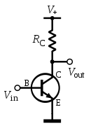 |
Inverts Inverter (logic gate) In digital logic, an inverter or NOT gate is a logic gate which implements logical negation. The truth table is shown on the right.This represents perfect switching behavior, which is the defining assumption in Digital electronics. In practice, actual devices have electrical characteristics that... the input signal |
| Common Gate / Common Base | 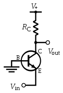 |
Typically used for current buffering (not voltage buffering); generally unsuitable for TTL voltage buffer | |
| Common Drain / Common Collector |  |
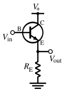 |
Unity-gain voltage buffer |
Integrated buffer amplifiers
It is common for a single packageDual in-line package
In microelectronics, a dual in-line package is an electronic device package with a rectangular housing and two parallel rows of electrical connecting pins. The package may be through-hole mounted to a printed circuit board or inserted in a socket.A DIP is usually referred to as a DIPn, where n is...
to contain several discrete buffer amplifiers. For example, a hex buffer is a single package containing 6 discrete buffer amplifiers, and an octal buffer is a single package containing 8 discrete buffer amplifiers.
Speaker array amplifiers
The majority of amplifiers used to drive large speaker arrays, such as those used for rock concerts, are unity-gain, high-current amplifiers. Some current amplifiers take the voltage output from Class A/B, B, or tube (valve) amplifiers, while others contain built-in voltage amplifiers as a pre-amp stage. The result is a signal nearly identical to the input signal in terms of voltage, but capable of sending high amounts of current into low impedance speaker arrays where the speakers are wired in parallel.Current buffer examples
Simple unity gain buffer amplifiers include the bipolar junction transistorBipolar junction transistor
|- align = "center"| || PNP|- align = "center"| || NPNA bipolar transistor is a three-terminal electronic device constructed of doped semiconductor material and may be used in amplifying or switching applications. Bipolar transistors are so named because their operation involves both electrons...
in common-base
Common base
In electronics, a common-base amplifier is one of three basic single-stage bipolar junction transistor amplifier topologies, typically used as a current buffer or voltage amplifier...
configuration, or the MOSFET
MOSFET
The metal–oxide–semiconductor field-effect transistor is a transistor used for amplifying or switching electronic signals. The basic principle of this kind of transistor was first patented by Julius Edgar Lilienfeld in 1925...
in common-gate
Common gate
In electronics, a common-gate amplifier is one of three basic single-stage field-effect transistor amplifier topologies, typically used as a current buffer or voltage amplifier...
configuration (called a current follower because the output current follows the input current). The current gain of a current buffer amplifier is (approximately) unity.
Single-transistor circuits
Figure 6 shows a bipolar current buffer biased with a current source (designated IE for DC emitter current) and driving another DC current source as active load (designated IC for DC collector current). The AC input signal current iin is applied to the emitter node of the transistor by an AC Norton current sourceNorton's theorem
Norton's theorem for linear electrical networks, known in Europe as the Mayer–Norton theorem, states that any collection of voltage sources, current sources, and resistors with two terminals is electrically equivalent to an ideal current source, I, in parallel with a single resistor, R...
with Norton resistance RS. The AC output current iout is delivered by the buffer via a large coupling capacitor to load RL. This coupling capacitor is large enough to be a short-circuit at frequencies of interest.
Because the transistor output resistance connects input and output sides of the circuit, there is a (very small) backward voltage feedback from the output to the input so this circuit is not unilateral. In addition, for the same reason, the input resistance depends (slightly) upon the output load resistance, and the output resistance depends significantly on the input driver resistance. For more detail see the article on common base amplifier
Common base
In electronics, a common-base amplifier is one of three basic single-stage bipolar junction transistor amplifier topologies, typically used as a current buffer or voltage amplifier...
.
See also
- PreamplifierPreamplifierA preamplifier is an electronic amplifier that prepares a small electrical signal for further amplification or processing. A preamplifier is often placed close to the sensor to reduce the effects of noise and interference. It is used to boost the signal strength to drive the cable to the main...
- Common baseCommon baseIn electronics, a common-base amplifier is one of three basic single-stage bipolar junction transistor amplifier topologies, typically used as a current buffer or voltage amplifier...
- Common gateCommon gateIn electronics, a common-gate amplifier is one of three basic single-stage field-effect transistor amplifier topologies, typically used as a current buffer or voltage amplifier...
- Common collectorCommon collectorIn electronics, a common-collector amplifier is one of three basic single-stage bipolar junction transistor amplifier topologies, typically used as a voltage buffer...
- Common drainCommon drainIn electronics, a common-drain amplifier, also known as a source follower, is one of three basic single-stage field effect transistor amplifier topologies, typically used as a voltage buffer. In this circuit the gate terminal of the transistor serves as the input, the source is the output, and the...
- Negative feedback amplifier