
Telegraphers equations
Encyclopedia
The telegrapher's equations (or just telegraph equations) are a pair of linear differential equation
s which describe the voltage
and current
on an electrical transmission line
with distance and time. The equations come from Oliver Heaviside
who in the 1880s developed the transmission line model which is described in this article. The model demonstrates that the electromagnetic waves can be reflected on the wire, and that wave patterns can appear along the line. The theory applies to transmission lines of all frequencies including high-frequency transmission line
s (such as telegraph wires and radio frequency
conductors), audio frequency (such as telephone lines), low frequency (such as power lines) and direct current.
 The telegrapher's equations, like all other equations describing electrical phenomena, can be held to result from Maxwell's equations
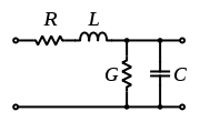
. In a more practical approach, one assumes that the conductors are composed of an infinite series of two-port elementary components, each representing an infinitesimally short segment of the transmission line:
It should be repeated for clarity that the model consists of an infinite series of the infinitesimal elements shown in the figure, and that the values of the components are specified per unit length so the picture of the component can be misleading. An alternative notation is to use ,
,  ,
,  and
and  to emphasize that the values are derivatives with respect to length. These quantities can also be known as the primary line constants
to distinguish from the secondary line constants derived from them, these being the characteristic impedance
, the propagation constant
, attenuation constant and phase constant. All these constants are constant with respect to time, voltage and current. They may be non-constant functions of frequency.
The Telegrapher's Equations are developed in similar forms in the following references:
Kraus,
Hayt,
Marshall,
Sadiku,
Harrington,
Karakash,
Metzger,
More extensive tables and tables for other gauges, temperatures and types are available in Reeve.
Chen gives the same data in a parameterized form that he states is usable up to 50 MHz.
The variation of R and L is mainly due to skin effect
and proximity effect
.
The constancy of the capacitance is a consequence of intentional design.
The variation of G can be inferred from Terman "The power factor ... tends to be independent of frequency, since the fraction of energy lost during each cycle ... is substantially independent of the number of cycles per second, over wide frequency ranges." A function of the form
 with ge close to 1.0 would fit the statement from Terman. Chen gives an equation of similar form.
G in this table can be modeled well with = 1MHz
 S/kft
S/kft
Usually the resistive losses grow proportionately to and dielectric losses grow proportionately to
  with ge > 0.5 so at a high enough frequency, dielectric losses will exceed resistive losses. In practice, before that point is reached, a transmission line with a better dielectric is used. The dielectric can be reduced down to air with an occasional plastic spacer.
These equations may be combined to form either of two exact wave equations:


In the steady-state case (assuming a sinusoidal wave , these reduce to
If the line has infinite length or when it is terminated with its characteristic impedance, these equations indicate the presence of a wave, travelling with a speed .
.
(Note that this propagation speed applies to the wave phenomenon on the line and has nothing to do with the electron drift velocity
. In other words, the electrical impulse travels very close to the speed of light, although the electrons themselves travel only a few centimeters per second.) For a coaxial transmission line, made of perfect conductors with vacuum between them, it can be shown that this speed is equal to the speed of light.
The Lossless line and Distortionless line are discussed in
Sadiku, and
Marshall,
By differentiating the first equation with respect to x and the second with respect to t, and some algebraic manipulation, we obtain a pair of hyperbolic partial differential equations each involving only one unknown:
Note that these equations resemble the homogeneous wave equation with extra terms in V and I and their first derivatives. These extra terms cause the signal to decay and spread out with time and distance. If the transmission line is only slightly lossy (small R and G = 0), signal strength will decay over distance as e-αx, where α = R/2Z0

where:
 is called the wavenumber
and has units of radian
s per meter,

f1 represents a wave traveling from left to right in a positive x direction whilst
f2 represents a wave traveling from right to left. It can be seen that the instantaneous voltage at any point x on the line is the sum of the voltages due to both waves.
Since the current I is related to the voltage V by the telegrapher's equations, we can write
where is the characteristic impedance
of the transmission line, which, for a lossless line is given by

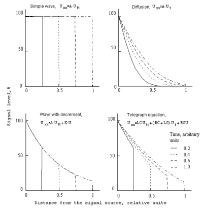 Depending on the parameters of the telegraph equation, the changes of the signal level distribution along the length of the single-dimensional transmission media may take the shape of the simple wave, wave with decrement, or the diffusion-like pattern of the telegraph equation. The shape of the diffusion-like pattern is caused by the effect of the shunt capacity.
This is not the only possible equivalent circuit. Voltage amplifiers and sensors can be replaced with current, transimpedance or transconductance amplifiers. Series impedances can be replaced with shunt admittances. The circuit can be augmented to account for different "grounds" at each end. The circuit can be made fully differential.
Differential equation
A differential equation is a mathematical equation for an unknown function of one or several variables that relates the values of the function itself and its derivatives of various orders...
s which describe the voltage
Voltage
Voltage, otherwise known as electrical potential difference or electric tension is the difference in electric potential between two points — or the difference in electric potential energy per unit charge between two points...
and current
Electric current
Electric current is a flow of electric charge through a medium.This charge is typically carried by moving electrons in a conductor such as wire...
on an electrical transmission line
Transmission line
In communications and electronic engineering, a transmission line is a specialized cable designed to carry alternating current of radio frequency, that is, currents with a frequency high enough that its wave nature must be taken into account...
with distance and time. The equations come from Oliver Heaviside
Oliver Heaviside
Oliver Heaviside was a self-taught English electrical engineer, mathematician, and physicist who adapted complex numbers to the study of electrical circuits, invented mathematical techniques to the solution of differential equations , reformulated Maxwell's field equations in terms of electric and...
who in the 1880s developed the transmission line model which is described in this article. The model demonstrates that the electromagnetic waves can be reflected on the wire, and that wave patterns can appear along the line. The theory applies to transmission lines of all frequencies including high-frequency transmission line
Transmission line
In communications and electronic engineering, a transmission line is a specialized cable designed to carry alternating current of radio frequency, that is, currents with a frequency high enough that its wave nature must be taken into account...
s (such as telegraph wires and radio frequency
Radio frequency
Radio frequency is a rate of oscillation in the range of about 3 kHz to 300 GHz, which corresponds to the frequency of radio waves, and the alternating currents which carry radio signals...
conductors), audio frequency (such as telephone lines), low frequency (such as power lines) and direct current.
The equations
Maxwell's equations
Maxwell's equations are a set of partial differential equations that, together with the Lorentz force law, form the foundation of classical electrodynamics, classical optics, and electric circuits. These fields in turn underlie modern electrical and communications technologies.Maxwell's equations...
. In a more practical approach, one assumes that the conductors are composed of an infinite series of two-port elementary components, each representing an infinitesimally short segment of the transmission line:
- The distributed resistanceElectrical resistanceThe electrical resistance of an electrical element is the opposition to the passage of an electric current through that element; the inverse quantity is electrical conductance, the ease at which an electric current passes. Electrical resistance shares some conceptual parallels with the mechanical...
 of the conductors is represented by a series resistor (expressed in ohmOhmThe ohm is the SI unit of electrical resistance, named after German physicist Georg Simon Ohm.- Definition :The ohm is defined as a resistance between two points of a conductor when a constant potential difference of 1 volt, applied to these points, produces in the conductor a current of 1 ampere,...
s per unit length). - The distributed inductance
 (due to the magnetic fieldMagnetic fieldA magnetic field is a mathematical description of the magnetic influence of electric currents and magnetic materials. The magnetic field at any given point is specified by both a direction and a magnitude ; as such it is a vector field.Technically, a magnetic field is a pseudo vector;...
around the wires, self-inductance, etc.) is represented by a series inductorInductorAn inductor is a passive two-terminal electrical component used to store energy in a magnetic field. An inductor's ability to store magnetic energy is measured by its inductance, in units of henries...
(henries per unit length). - The capacitance
 between the two conductors is represented by a shuntShunt (electrical)In electronics, a shunt is a device which allows electric current to pass around another point in the circuit. The term is also widely used in photovoltaics to describe an unwanted short circuit between the front and back surface contacts of a solar cell, usually caused by wafer damage.-Defective...
capacitorCapacitorA capacitor is a passive two-terminal electrical component used to store energy in an electric field. The forms of practical capacitors vary widely, but all contain at least two electrical conductors separated by a dielectric ; for example, one common construction consists of metal foils separated...
C (faradFaradThe farad is the SI unit of capacitance. The unit is named after the English physicist Michael Faraday.- Definition :A farad is the charge in coulombs which a capacitor will accept for the potential across it to change 1 volt. A coulomb is 1 ampere second...
s per unit length). - The conductance
 of the dielectric material separating the two conductors is represented by a shunt resistor between the signal wire and the return wire (siemensSiemens (unit)The siemens is the SI derived unit of electric conductance and electric admittance. Conductance and admittance are the reciprocals of resistance and impedance respectively, hence one siemens is equal to the reciprocal of one ohm, and is sometimes referred to as the mho. In English, the term...
per unit length). This resistor in the model has a resistance of ohms.
ohms.
It should be repeated for clarity that the model consists of an infinite series of the infinitesimal elements shown in the figure, and that the values of the components are specified per unit length so the picture of the component can be misleading. An alternative notation is to use
, , and to emphasize that the values are derivatives with respect to length. These quantities can also be known as the primary line constantsPrimary line constants
The primary line constants are parameters that describe the characteristics of copper transmission lines in terms of the physical electrical properties of the line. The primary line constants are only relevant to copper lines and are to be contrasted with the secondary line constants, which can...
to distinguish from the secondary line constants derived from them, these being the characteristic impedance
Characteristic impedance
The characteristic impedance or surge impedance of a uniform transmission line, usually written Z_0, is the ratio of the amplitudes of a single pair of voltage and current waves propagating along the line in the absence of reflections. The SI unit of characteristic impedance is the ohm...
, the propagation constant
Propagation constant
The propagation constant of an electromagnetic wave is a measure of the change undergone by the amplitude of the wave as it propagates in a given direction. The quantity being measured can be the voltage or current in a circuit or a field vector such as electric field strength or flux density...
, attenuation constant and phase constant. All these constants are constant with respect to time, voltage and current. They may be non-constant functions of frequency.
The Telegrapher's Equations are developed in similar forms in the following references:
Kraus,
Hayt,
Marshall,
Sadiku,
Harrington,
Karakash,
Metzger,
Values of Primary Parameters for Telephone Cable
Representative parameter data for 24 gauge PIC telephone cable at 70°F| Frequency | R | L | G | C |
|---|---|---|---|---|
| Hz Hertz The hertz is the SI unit of frequency defined as the number of cycles per second of a periodic phenomenon. One of its most common uses is the description of the sine wave, particularly those used in radio and audio applications.... | Ω Ohm The ohm is the SI unit of electrical resistance, named after German physicist Georg Simon Ohm.- Definition :The ohm is defined as a resistance between two points of a conductor when a constant potential difference of 1 volt, applied to these points, produces in the conductor a current of 1 ampere,... /kft | mH/kft | µS Siemens (unit) The siemens is the SI derived unit of electric conductance and electric admittance. Conductance and admittance are the reciprocals of resistance and impedance respectively, hence one siemens is equal to the reciprocal of one ohm, and is sometimes referred to as the mho. In English, the term... /kft | nF Farad The farad is the SI unit of capacitance. The unit is named after the English physicist Michael Faraday.- Definition :A farad is the charge in coulombs which a capacitor will accept for the potential across it to change 1 volt. A coulomb is 1 ampere second... /kft |
| 1 | 52.50 | 0.1868 | 0.000 | 15.72 |
| 1k | 52.51 | 0.1867 | 0.022 | 15.72 |
| 10k | 52.64 | 0.1859 | 0.162 | 15.72 |
| 100k | 58.41 | 0.1770 | 1.197 | 15.72 |
| 1M | 141.30 | 0.1543 | 8.873 | 15.72 |
| 2M | 196.03 | 0.1482 | 16.217 | 15.72 |
| 5M | 304.62 | 0.1425 | 35.989 | 15.72 |
More extensive tables and tables for other gauges, temperatures and types are available in Reeve.
Chen gives the same data in a parameterized form that he states is usable up to 50 MHz.
The variation of R and L is mainly due to skin effect
Skin effect
Skin effect is the tendency of an alternating electric current to distribute itself within a conductor with the current density being largest near the surface of the conductor, decreasing at greater depths. In other words, the electric current flows mainly at the "skin" of the conductor, at an...
and proximity effect
Proximity effect (electromagnetism)
In a conductor carrying alternating current, if currents are flowing through one or more other nearby conductors, such as within a closely wound coil of wire, the distribution of current within the first conductor will be constrained to smaller regions. The resulting current crowding is termed the...
.
The constancy of the capacitance is a consequence of intentional design.
The variation of G can be inferred from Terman "The power factor ... tends to be independent of frequency, since the fraction of energy lost during each cycle ... is substantially independent of the number of cycles per second, over wide frequency ranges." A function of the form
with ge close to 1.0 would fit the statement from Terman. Chen gives an equation of similar form.G in this table can be modeled well with
= 1MHzS/kft
- ge = 0.87
Usually the resistive losses grow proportionately to
and dielectric losses grow proportionately to with ge > 0.5 so at a high enough frequency, dielectric losses will exceed resistive losses. In practice, before that point is reached, a transmission line with a better dielectric is used. The dielectric can be reduced down to air with an occasional plastic spacer.Lossless transmission
When the elements R and G are very small, their effects can be neglected, and the transmission line is considered as an idealized, lossless, structure. In this case, the model depends only on the L and C elements, and we obtain a pair of first-order partial differential equations, one function describing the voltage V along the line and the other the current I, both function of position x and time t:These equations may be combined to form either of two exact wave equations:
In the steady-state case (assuming a sinusoidal wave
, these reduce to- where
 is the frequency of the steady-state wave
If the line has infinite length or when it is terminated with its characteristic impedance, these equations indicate the presence of a wave, travelling with a speed
.(Note that this propagation speed applies to the wave phenomenon on the line and has nothing to do with the electron drift velocity
Drift velocity
The drift velocity is the average velocity that a particle, such as an electron, attains due to an electric field. It can also be referred to as Axial Drift Velocity since particles defined are assumed to be moving along a plane. In general, an electron will 'rattle around' in a conductor at the...
. In other words, the electrical impulse travels very close to the speed of light, although the electrons themselves travel only a few centimeters per second.) For a coaxial transmission line, made of perfect conductors with vacuum between them, it can be shown that this speed is equal to the speed of light.
The Lossless line and Distortionless line are discussed in
Sadiku, and
Marshall,
Lossy transmission line
When the loss elements R and G are not negligible, the original differential equations describing the elementary segment of line becomeBy differentiating the first equation with respect to x and the second with respect to t, and some algebraic manipulation, we obtain a pair of hyperbolic partial differential equations each involving only one unknown:
Note that these equations resemble the homogeneous wave equation with extra terms in V and I and their first derivatives. These extra terms cause the signal to decay and spread out with time and distance. If the transmission line is only slightly lossy (small R and G = 0), signal strength will decay over distance as e-αx, where α = R/2Z0
Direction of signal propagations
The wave equations above indicate that there are two solutions for the travelling wave: one forward and one reverse. Assuming a simplification of being lossless (requiring both R=0 and G=0) the solution can be represented as:where:
is called the wavenumberWavenumber
In the physical sciences, the wavenumber is a property of a wave, its spatial frequency, that is proportional to the reciprocal of the wavelength. It is also the magnitude of the wave vector...
and has units of radian
Radian
Radian is the ratio between the length of an arc and its radius. The radian is the standard unit of angular measure, used in many areas of mathematics. The unit was formerly a SI supplementary unit, but this category was abolished in 1995 and the radian is now considered a SI derived unit...
s per meter,
- ω is the angular frequency (in radians per second),
 and
and  can be any functions whatsoever, and
- is the waveform's propagation speed (also known as phase velocityPhase velocityThe phase velocity of a wave is the rate at which the phase of the wave propagates in space. This is the speed at which the phase of any one frequency component of the wave travels. For such a component, any given phase of the wave will appear to travel at the phase velocity...
).
f1 represents a wave traveling from left to right in a positive x direction whilst
f2 represents a wave traveling from right to left. It can be seen that the instantaneous voltage at any point x on the line is the sum of the voltages due to both waves.
Since the current I is related to the voltage V by the telegrapher's equations, we can write
where
is the characteristic impedanceCharacteristic impedance
The characteristic impedance or surge impedance of a uniform transmission line, usually written Z_0, is the ratio of the amplitudes of a single pair of voltage and current waves propagating along the line in the absence of reflections. The SI unit of characteristic impedance is the ohm...
of the transmission line, which, for a lossless line is given by
Signal pattern examples
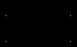
Solutions of the Telegrapher's Equations as Circuit Components
The solutions of the telegrapher's equations can be inserted into a circuit as components of an equivalent sub-circuit as shown the figure. As drawn, all voltages are with respect to ground and all amplifiers have unshown connections to ground. An example of a transmission line modeled by this circuit would be an unbalanced transmission line such as a strip line on a circuit board. The impedance Z(s), the voltage doubler (the triangle with the number "2") and the difference amplifier (the triangle with the number "1") account for the interaction of the transmission line with the rest of the circuit. The T(s) blocks account for delay, attenuation, dispersion and whatever happens to the signal in transit. One of the T(s) blocks carries the "forward wave" and the other carries the "backward wave". The circuit, as depicted, is fully symmetric, although it is not drawn that way. The circuit depicted is equivalent to a transmission line connected from V1 to V2 in the sense that V1, V2, I1 and I2 would be same whether this circuit or an actual transmission line was connected between V1 and V2. There is no implication that there are actually amplifiers inside the transmission line.This is not the only possible equivalent circuit. Voltage amplifiers and sensors can be replaced with current, transimpedance or transconductance amplifiers. Series impedances can be replaced with shunt admittances. The circuit can be augmented to account for different "grounds" at each end. The circuit can be made fully differential.