
SWR meter
Encyclopedia
Standing wave ratio
In telecommunications, standing wave ratio is the ratio of the amplitude of a partial standing wave at an antinode to the amplitude at an adjacent node , in an electrical transmission line....
in a transmission line. The meter can be used to indicate the degree of mismatch between a transmission line
Transmission line
In communications and electronic engineering, a transmission line is a specialized cable designed to carry alternating current of radio frequency, that is, currents with a frequency high enough that its wave nature must be taken into account...
and its load (usually a radio antenna
Antenna (radio)
An antenna is an electrical device which converts electric currents into radio waves, and vice versa. It is usually used with a radio transmitter or radio receiver...
), or evaluate the effectiveness of impedance matching
Impedance matching
In electronics, impedance matching is the practice of designing the input impedance of an electrical load to maximize the power transfer and/or minimize reflections from the load....
efforts.
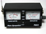
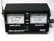
Directional SWR Meter
A directional SWR meter measures the magnitude of the forward & reflected waves by sensing each one individually, with directional couplers. A calculation can then be performed to arrive at the SWR.
Electrical impedance
Electrical impedance, or simply impedance, is the measure of the opposition that an electrical circuit presents to the passage of a current when a voltage is applied. In quantitative terms, it is the complex ratio of the voltage to the current in an alternating current circuit...
of the sense lines. The diodes convert the magnitudes of the forward & reverse waves to FWD and REV DC voltages, respectively, which are then smoothed by the capacitors.
To calculate the VSWR, first calculate the reflection coefficient:

Then calculate the VSWR:

In a passive meter, this is usually indicated on a non-linear scale.
SWR Bridge
SWR can also be measured using an impedance bridge circuitBridge circuit
A bridge circuit is a type of electrical circuit in which two circuit branches are "bridged" by a third branch connected between the first two branches at some intermediate point along them. The bridge was originally developed for laboratory measurement purposes and one of the intermediate...
. The bridge is balanced (0 volts across the detector) only when the test impedance exactly matches the reference impedance. When a transmission line is mismatched (SWR > 1:1), its input impedance deviates from its characteristic impedance; thus, a bridge can be used to determine the presence or absence of a low SWR.
To test for a match, the reference impedance of the bridge is set to the expected load impedance (for example, 50 ohms), and the transmission line connected as the unknown impedance. RF
Radio frequency
Radio frequency is a rate of oscillation in the range of about 3 kHz to 300 GHz, which corresponds to the frequency of radio waves, and the alternating currents which carry radio signals...
power is applied to the circuit. The voltage at the line input represents the vector sum of the forward wave, and the wave reflected from the load. If the characteristic impedance of the line is known to be 50 ohms, we know the magnitude and phase of the forward wave; it is the same wave present on the other side of the detector. Subtracting this known wave from the wave present at the line input yields the reflected wave. Properly designed, a bridge circuit can be used not only to indicate a match, but the degree of mismatch - thus making it possible to calculate the SWR. This usually involves alternately connecting the reference wave and the reflected wave to a power meter, and comparing the magnitudes of the resulting deflections.
Limitations
Note that an SWR meter does not measure the actual impedance of a load (i.e., the resistance and reactance), but only the mismatch ratio. To measure the actual impedance, an antenna analyzerAntenna analyzer
An antenna analyzer is a device used for measuring the efficiency of antenna systems in radio electronics applications.-Theory of operation:...
or other similar RF measuring device is required. Note also that for accurate readings, the SWR meter must be matched to the line impedance, usually 50 or 75 ohms. To accommodate multiple impedances, some SWR meters have switches on the rear, to select the resistance appropriate for the sense lines.
An SWR meter should be connected to the line as close as possible to the antenna: All practical transmission lines have a certain amount of loss, which causes the reflected wave to be attenuated as it travels back along the line. Thus, the SWR is highest closest to the load, and only improves as the distance from the load increases.
When not actually measuring SWR, it is best to remove the more usual types of passive SWR meter from the line. This is because the internal diodes of such meters can generate harmonics when transmitting, and intermodulation
Intermodulation
Intermodulation or intermodulation distortion is the amplitude modulation of signals containing two or more different frequencies in a system with nonlinearities...
products when receiving. Because active SWR meters do not usually suffer from this effect, they can normally be left in without causing such problems.