
Bridge circuit
Encyclopedia
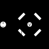
A bridge circuit is a type of electrical circuit in which two circuit branches (usually in parallel with each other) are "bridged" by a third branch connected between the first two branches at some intermediate point along them. The bridge was originally developed for laboratory measurement purposes and one of the intermediate bridging points is often adjustable when so used. Bridge circuits now find many applications, both linear and non-linear, including in instrumentation
, filter
ing and power conversion
.
 The best-known bridge circuit, the Wheatstone bridge
, was invented by Samuel Hunter Christie
and popularized by Charles Wheatstone
, and is used for measuring resistance
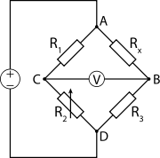
. It is constructed from four resistors, one of which has an unknown value (Rx), one of which is variable (R2), and two of which are fixed and equal (R1 and R3), connected as the sides of a square. Two opposite corners of the square are connected to a source of electric current, such as a battery. A galvanometer
is connected across the other two opposite corners. The variable resistor is adjusted until the galvanometer reads zero. It is then known that the ratio between the variable resistor and its neighbour is equal to the ratio between the unknown resistor and its neighbour, and this enables the value of the unknown resistor to be calculated.
The Wheatstone bridge has also been developed to measure impedance
in AC circuits, resulting in designs such as the Wien bridge
, the Maxwell bridge
and the Heaviside bridge. All are based on the same principle, which is to compare the output of two potentiometer
s sharing a common source.
In power supply design, a bridge circuit or bridge rectifier is an arrangement of diode
s or similar devices used to rectify an electric current, i.e. to convert it from an unknown or alternating polarity to a direct current of known polarity.
In some motor controller
s, a H-bridge
is used to control the direction the motor turns.
Instrumentation
Instrumentation is defined as the art and science of measurement and control of process variables within a production, or manufacturing area....
, filter
Electronic filter
Electronic filters are electronic circuits which perform signal processing functions, specifically to remove unwanted frequency components from the signal, to enhance wanted ones, or both...
ing and power conversion
Power converter
A power converter is an electrical or electro-mechanical device for converting electrical energy. It may be converting AC to or from DC, or the voltage or frequency, or some combination of these.Amongst the many devices that are used for this purpose are;...
.
Wheatstone bridge
A Wheatstone bridge is an electrical circuit used to measure an unknown electrical resistance by balancing two legs of a bridge circuit, one leg of which includes the unknown component. Its operation is similar to the original potentiometer. It was invented by Samuel Hunter Christie in 1833 and...
, was invented by Samuel Hunter Christie
Samuel Hunter Christie
Samuel Hunter Christie was a British scientist and mathematician.He studied mathematics at Trinity College, Cambridge where he was second wrangler. He was particularly interested in magnetism, studying the earth's magnetic field and designing improvements to the magnetic compass...
and popularized by Charles Wheatstone
Charles Wheatstone
Sir Charles Wheatstone FRS , was an English scientist and inventor of many scientific breakthroughs of the Victorian era, including the English concertina, the stereoscope , and the Playfair cipher...
, and is used for measuring resistance
Electrical resistance
The electrical resistance of an electrical element is the opposition to the passage of an electric current through that element; the inverse quantity is electrical conductance, the ease at which an electric current passes. Electrical resistance shares some conceptual parallels with the mechanical...
. It is constructed from four resistors, one of which has an unknown value (Rx), one of which is variable (R2), and two of which are fixed and equal (R1 and R3), connected as the sides of a square. Two opposite corners of the square are connected to a source of electric current, such as a battery. A galvanometer
Galvanometer
A galvanometer is a type of ammeter: an instrument for detecting and measuring electric current. It is an analog electromechanical transducer that produces a rotary deflection of some type of pointer in response to electric current flowing through its coil in a magnetic field. .Galvanometers were...
is connected across the other two opposite corners. The variable resistor is adjusted until the galvanometer reads zero. It is then known that the ratio between the variable resistor and its neighbour is equal to the ratio between the unknown resistor and its neighbour, and this enables the value of the unknown resistor to be calculated.
The Wheatstone bridge has also been developed to measure impedance
Electrical impedance
Electrical impedance, or simply impedance, is the measure of the opposition that an electrical circuit presents to the passage of a current when a voltage is applied. In quantitative terms, it is the complex ratio of the voltage to the current in an alternating current circuit...
in AC circuits, resulting in designs such as the Wien bridge
Wien bridge
The Wien bridge is a type of bridge circuit that was developed by Max Wien in 1891. The bridge comprises four resistors and two capacitors.Bridge circuits were a common way of measuring component values by comparing them to known values...
, the Maxwell bridge
Maxwell bridge
|- align = "center"|| A Maxwell bridge is a type of Wheatstone bridge used to measure an unknown inductance in terms of calibrated resistance and capacitance...
and the Heaviside bridge. All are based on the same principle, which is to compare the output of two potentiometer
Potentiometer
A potentiometer , informally, a pot, is a three-terminal resistor with a sliding contact that forms an adjustable voltage divider. If only two terminals are used , it acts as a variable resistor or rheostat. Potentiometers are commonly used to control electrical devices such as volume controls on...
s sharing a common source.
In power supply design, a bridge circuit or bridge rectifier is an arrangement of diode
Diode
In electronics, a diode is a type of two-terminal electronic component with a nonlinear current–voltage characteristic. A semiconductor diode, the most common type today, is a crystalline piece of semiconductor material connected to two electrical terminals...
s or similar devices used to rectify an electric current, i.e. to convert it from an unknown or alternating polarity to a direct current of known polarity.
In some motor controller
Motor controller
A motor controller is a device or group of devices that serves to govern in some predetermined manner the performance of an electric motor. A motor controller might include a manual or automatic means for starting and stopping the motor, selecting forward or reverse rotation, selecting and...
s, a H-bridge
H-bridge
An H bridge is an electronic circuit that enables a voltage to be applied across a load in either direction. These circuits are often used in robotics and other applications to allow DC motors to run forwards and backwards...
is used to control the direction the motor turns.
See also
- Bridged T circuit
- Carey Foster bridgeCarey Foster bridgeIn electronics, the Carey Foster bridge is a bridge circuit used to measure low resistances, or to measure small differences between two large resistances. It was invented by Carey Foster as a variant on the Wheatstone bridge...
- Fontana bridgeFontana bridgeA Fontana bridge is a type of bridge circuit that implements a wide frequency band voltage-to-current converter. The converter is characterized by a combination of positive and negative feedback loops, implicit in this bridge configuration...
- Graetz bridge
- Hay bridgeHay BridgeThe Hay Bridge is a bridge across the Griboedov Canal in Saint Petersburg, Russia.- History :The bridge gets its name from the nearby Sennaya Square....
- Kelvin bridgeKelvin bridgeA Kelvin bridge is a measuring instrument invented by William Thomson, 1st Baron Kelvin. It is used to measure an unknown electrical resistance below 1 Ω. Its operation is similar to the Wheatstone bridge except for the presence of additional resistors...
- Lattice filter
- Maxwell bridgeMaxwell bridge|- align = "center"|| A Maxwell bridge is a type of Wheatstone bridge used to measure an unknown inductance in terms of calibrated resistance and capacitance...
- Murray loop bridgeMurray loop bridgeMurray loop bridge is a bridge circuit used for locating faults in underground or underwater cables. It has been used for more than 100 years....
- Owen bridge
- Phantom circuitPhantom circuitIn telecommunication and electrical engineering, a phantom circuit is an electrical circuit derived from suitably arranged wires with one or more conductive paths being a circuit in itself and at the same time acting as one conductor of another circuit....
- a use of balanced bridge circuits - Resonance bridge
- Schering bridge
- Wheatstone bridgeWheatstone bridgeA Wheatstone bridge is an electrical circuit used to measure an unknown electrical resistance by balancing two legs of a bridge circuit, one leg of which includes the unknown component. Its operation is similar to the original potentiometer. It was invented by Samuel Hunter Christie in 1833 and...
- Wien bridgeWien bridgeThe Wien bridge is a type of bridge circuit that was developed by Max Wien in 1891. The bridge comprises four resistors and two capacitors.Bridge circuits were a common way of measuring component values by comparing them to known values...
Gallery
External links
- Jim WilliamsJim Williams (analog designer)James M. "Jim" Williams was an analog circuit designer and technical author who worked for the Massachusetts Institute of Technology , Philbrick, National Semiconductor and Linear Technology Corporation...
, "Bridge circuits: Marrying gain and balance", Linear Technology Application Note 43, June 1990. - Bridge circuits - Chapter 8 from an online book.
- Wien, Shering, Hay, Owen, Maxwell, and Resonance Bridges - With balance equations