

High-Level Data Link Control
Encyclopedia
High-Level Data Link Control (HDLC) is a bit-oriented
synchronous
data link layer
protocol
developed by the International Organization for Standardization
(ISO). The original ISO standards for HDLC are:
The current standard for HDLC is ISO 13239, which replaces all of those standards.
HDLC provides both connection-oriented
and connectionless service
.
HDLC can be used for point to multipoint connections, but is now used almost exclusively to connect one device to another, using what is known as Asynchronous Balanced Mode
(ABM). The original master-slave modes Normal Response Mode (NRM) and Asynchronous Response Mode (ARM) are rarely used.
's SDLC
protocol, which is the layer 2 protocol for IBM's Systems Network Architecture
(SNA). It was extended and standardized by the ITU
as LAP, while ANSI
named their essentially identical version ADCCP.
Derivatives have since appeared in innumerable standards. It was adopted into the X.25
protocol stack as LAPB
, into the V.42 protocol as LAPM
, into the Frame Relay
protocol stack as LAPF and into the ISDN protocol stack as LAPD
.
HDLC was the inspiration for the IEEE 802.2
LLC
protocol, and it is the basis for the framing mechanism used with the PPP
on synchronous lines, as used by many servers to connect to a WAN
, most commonly the Internet
.
A mildly different version is also used as the control channel for E-carrier
(E1) and SONET
multichannel telephone lines. Some vendors, such as Cisco, implemented protocols such as Cisco HDLC
that used the low-level HDLC framing techniques but added a protocol field to the standard HDLC header. More importantly, HDLC is the default encapsulation for serial interfaces on Cisco routers. It has also been used on Tellabs DXX
for destination of Trunk.
can be transmitted over synchronous or asynchronous
links. Those links have no mechanism to mark the beginning or end of a frame, so the beginning and end of each frame has to be identified. This is done by using a frame delimiter, or flag, which is a unique sequence of bits that is guaranteed not to be seen inside a frame. This sequence is '01111110', or, in hexadecimal
notation, 0x7E. Each frame begins and ends with a frame delimiter. A frame delimiter at the end of a frame may also mark the start of the next frame. A sequence of 7 or more consecutive 1-bits within a frame will cause the frame to be aborted.
When no frames are being transmitted on a simplex or full-duplex synchronous link, a frame delimiter is continuously transmitted on the link. Using the standard NRZI encoding from bits to line levels (0 bit = transition, 1 bit = no transition), this generates one of two continuous waveforms, depending on the initial state:
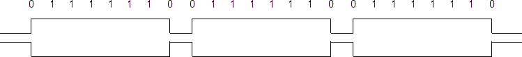
This is used by modem
s to train and synchronize their clocks via phase-locked loop
s. Some protocols allow the 0-bit at the end of a frame delimiter to be shared with the start of the next frame delimiter, i.e. '011111101111110'.
For half-duplex or multi-drop communication, where several transmitters share a line, a receiver on the line will see continuous idling 1-bits in the inter-frame period when no transmitter is active.
Since the flag sequence could appear in user data, such sequences must be modified during transmission to keep the receiver from detecting a false frame delimiter.
The receiver must also detect when this has occurred so that the original data stream can be restored before it is passed to higher layer protocols. This can be done using bit stuffing, in which a "0" is added after the occurrence of every "11111" in the data. The receiver, when detects these "11111" in the data, removes a "0" added by the transmitter.
. Any time that 5 consecutive 1-bits appear in the transmitted data, the data is paused and a 0-bit is transmitted. This ensures that no more than 5 consecutive 1-bits will be sent. The receiving device knows this is being done, and after seeing 5 1-bits in a row, a following 0-bit is stripped out of the received data. If the following bit is a 1-bit, the receiver has found a flag.
This also (assuming NRZI with transition for 0 encoding of the output) provides a minimum of one transition per 6 bit times during transmission of data, and one transition per 7 bit times during transmission of flag, so the receiver can stay in sync with the transmitter. Note however, that for this purpose encodings such as 8b/10b encoding
are better suited.
HDLC transmits bytes of data with the least significant bit first (little-endian order).
serial port
s, bits are sent in groups of 8, and bit-stuffing is inconvenient. Instead they use "control-octet transparency", also called "byte stuffing" or "octet stuffing". The frame boundary octet is 01111110, (7E in hexadecimal
notation). A "control escape octet
", has the bit sequence '01111101', (7D hexadecimal). If either of these two octets appears in the transmitted data, an escape octet is sent, followed by the original data octet with bit 5 inverted. For example, the data sequence "01111110" (7E hex) would be transmitted as "01111101 01011110" ("7D 5E" hex). Other reserved octet values (such as XON or XOFF
) can be escaped in the same way if necessary.
Note that the end flag of one frame may be (but does not have to be) the beginning (start) flag of the next frame.
Data is usually sent in multiples of 8 bits, but only some variants require this; others theoretically permit data alignments
on other than 8-bit boundaries.
The frame check sequence
(FCS) is a 16-bit CRC-CCITT or a 32-bit CRC-32 computed over the Address, Control, and Information fields. It provides a means by which the receiver can detect errors that may have been induced during the transmission of the frame, such as lost bits, flipped bits, and extraneous bits. However, given that the algorithms used to calculate the FCS are such that the probability of certain types of transmission errors going undetected increases with the length of the data being checked for errors, the FCS can implicitly limit the practical size of the frame.
If the receiver's calculation of the FCS does not match that of the sender's, indicating that the frame contains errors, the receiver can either send a negative acknowledge
packet to the sender, or send nothing. After either receiving a negative acknowledge packet or timing out waiting for a positive acknowledge packet, the sender can retransmit the failed frame.
The FCS was implemented because many early communication links had a relatively high bit error rate
, and the FCS could readily be computed by simple, fast circuitry or software. More effective forward error correction
schemes are now widely used by other protocols.
(SDLC
) was originally designed to connect one computer with multiple peripherals. The original "normal response mode" is a master-slave mode where the computer (or primary terminal) gives each peripheral (secondary terminal) permission to speak in turn. Because all communication is either to or from the primary terminal, frames include only one address, that of the secondary terminal; the primary terminal is not assigned an address. There is also a strong distinction between commands sent by the primary to a secondary, and responses sent by a secondary to the primary. Commands and responses are in fact indistinguishable; the only difference is the direction in which they are transmitted.
Normal response mode allows operation over half-duplex communication links, as long as the primary is aware that it
may not transmit when it has given permission to a secondary.
Asynchronous response mode is an HDLC addition for use over full-duplex links. While retaining the primary/secondary distinction, it allows the secondary to transmit at any time.
Asynchronous balanced mode added the concept of a combined terminal which can act as both a primary and a secondary. There are some subtleties about this mode of operation; while many features of the protocol do not care whether they are in a command or response frame, some do, and the address field of a received frame must be examined to determine whether it contains a command (the address received is ours) or a response (the address received is that of the other terminal).
Some HDLC variants extend the address field to include both source and destination addresses, or an explicit command/response bit.
The general format of the control field is:
There are also extended (2-byte) forms of I and S frames. Again, the least significant bit (rightmost in this table) is sent first.
The bit is used as a token
that is passed back and forth between the stations. Only one token should exist at a time. The secondary only sends a Final when it has received a Poll from the primary. The primary only sends a Poll when it has received a Final back from the secondary, or after a timeout indicating that the bit has been lost.
When operating as a combined station, it is important to maintain the distinction between P and F bits, because there may be two checkpoint cycles operating simultaneously. A P bit arriving in a command from the remote station is not in response to our P bit; only an F bit arriving in a response is.
N(R) provides a positive acknowledgement for the receipt of I-frames from the other side of the link.
Its value is always the first frame not received; it acknowledges that all frames with N(S) values up to N(R)-1 (modulo 8 or modulo 128) have been received and indicates the N(S) of the next frame it expects to receive.
N(R) operates the same way whether it is part of a command or response. A combined station only has
one sequence number space.
The least significant bit (first transmitted) defines the frame type. 0 means an I-frame.
Except for the interpretation of the P/F field, there is no difference between a command I frame and a response I frame; when P/F is 0, the two forms are exactly equivalent.
The S-frame control field includes a leading "10" indicating that it is an S-frame. This is followed by a 2-bit type, a poll/final bit, and a sequence number. If 7-bit sequence numbers are used, there is also a 4-bit padding field.
The first 2 bits mean it is an S-frame. All S frames include a P/F bit and a receive sequence number as described above. Except for the interpretation of the P/F field, there is no difference between a command S frame and a response S frame; when P/F is 0, the two forms are exactly equivalent.
The 2-bit type field encodes the type of S frame.
The first 2 bits (11) mean it is a U-frame. The 5 type bits (2 before P/F bit and 3 bit after P/F bit) can create 32 different types of U-frame
The three link configurations are:
An additional link configuration is Disconnected mode. This is the mode that a secondary station is in before it is initialized by the primary, or when it is explicitly disconnected. In this mode, the secondary responds to almost every frame other than a mode set command with a "Disconnected mode" response. The purpose of this mode is to allow the primary to reliably detect a secondary being powered off or otherwise reset..
The HDLC module on the other end transmits (UA) frame when the request is accepted. And if the request is rejected it sends (DM) disconnect mode frame.
The UI, XID and TEST frames contain a payload, and can be used as both commands and responses.
The FRMR frame contains a payload describing the unacceptable frame. The first 1 or 2 bytes are a copy of the rejected control field, the next 1 or 2 contain the current send and receive sequence numbers, and the following 4 or 5 bits indicate the reason for the rejection.
Bit-oriented protocol
A bit-oriented protocol is a communications protocol that sees the transmitted data as an opaque stream of bits with no semantics, or meaning. Control codes are defined in terms of bit sequences instead of characters. Bit oriented protocol can transfer data frames regardless of frame contents...
synchronous
Synchronization (computer science)
In computer science, synchronization refers to one of two distinct but related concepts: synchronization of processes, and synchronization of data. Process synchronization refers to the idea that multiple processes are to join up or handshake at a certain point, so as to reach an agreement or...
data link layer
Data link layer
The data link layer is layer 2 of the seven-layer OSI model of computer networking. It corresponds to, or is part of the link layer of the TCP/IP reference model....
protocol
Communications protocol
A communications protocol is a system of digital message formats and rules for exchanging those messages in or between computing systems and in telecommunications...
developed by the International Organization for Standardization
International Organization for Standardization
The International Organization for Standardization , widely known as ISO, is an international standard-setting body composed of representatives from various national standards organizations. Founded on February 23, 1947, the organization promulgates worldwide proprietary, industrial and commercial...
(ISO). The original ISO standards for HDLC are:
- ISO 3309 — Frame Structure
- ISO 4335 — Elements of Procedure
- ISO 6159 — Unbalanced Classes of Procedure
- ISO 6256 — Balanced Classes of Procedure
The current standard for HDLC is ISO 13239, which replaces all of those standards.
HDLC provides both connection-oriented
Connection-oriented protocol
A connection-oriented networking protocol is one that establishes a communication session, then delivers a stream of data in the same order as it was sent. It may be a circuit switched connection, or a virtual circuit connection in a packet switched network...
and connectionless service
Connectionless protocol
In telecommunications, connectionless describes communication between two network end points in which a message can be sent from one end point to another without prior arrangement. The device at one end of the communication transmits data addressed to the other, without first ensuring that the...
.
HDLC can be used for point to multipoint connections, but is now used almost exclusively to connect one device to another, using what is known as Asynchronous Balanced Mode
Asynchronous Balanced Mode
Asynchronous Balanced Mode is a communication mode of HDLC and derivative protocols, supporting peer-oriented point-to-point communications between two nodes, where either node can initiate transmission....
(ABM). The original master-slave modes Normal Response Mode (NRM) and Asynchronous Response Mode (ARM) are rarely used.
History
HDLC is based on IBMIBM
International Business Machines Corporation or IBM is an American multinational technology and consulting corporation headquartered in Armonk, New York, United States. IBM manufactures and sells computer hardware and software, and it offers infrastructure, hosting and consulting services in areas...
's SDLC
Synchronous Data Link Control
Synchronous Data Link Control is a computer communications protocol. It is the layer 2 protocol for IBM's Systems Network Architecture . SDLC supports multipoint links as well as error correction. It also runs under the assumption that an SNA header is present after the SDLC header...
protocol, which is the layer 2 protocol for IBM's Systems Network Architecture
Systems Network Architecture
Systems Network Architecture is IBM's proprietary networking architecture created in 1974. It is a complete protocol stack for interconnecting computers and their resources. SNA describes the protocol and is, in itself, not actually a program...
(SNA). It was extended and standardized by the ITU
International Telecommunication Union
The International Telecommunication Union is the specialized agency of the United Nations which is responsible for information and communication technologies...
as LAP, while ANSI
Ansi
Ansi is a village in Kaarma Parish, Saare County, on the island of Saaremaa, Estonia....
named their essentially identical version ADCCP.
Derivatives have since appeared in innumerable standards. It was adopted into the X.25
X.25
X.25 is an ITU-T standard protocol suite for packet switched wide area network communication. An X.25 WAN consists of packet-switching exchange nodes as the networking hardware, and leased lines, Plain old telephone service connections or ISDN connections as physical links...
protocol stack as LAPB
LAPB
Link Access Procedure, Balanced implements the data link layer as defined in the X.25 protocol suite. LAPB is a bit-oriented protocol derived from HDLC that ensures that frames are error free and in the right sequence. LAPB is specified in and ISO/IEC 7776...
, into the V.42 protocol as LAPM
LAPM
Link Access Procedure for Modems is part of the V.42 error correction protocol for modems.LAPM is an error control protocol defined in ITU-T recommendations V.42. Like many data link layer protocols, it is a variant of HDLC...
, into the Frame Relay
Frame relay
Frame Relay is a standardized wide area network technology that specifies the physical and logical link layers of digital telecommunications channels using a packet switching methodology...
protocol stack as LAPF and into the ISDN protocol stack as LAPD
Link Access Procedures, D channel
Link Access Procedures on the D channel , specified in ITU-T Q.920 and ITU-T Q.921, is the second layer protocol on the ISDN protocol stack in the D channel.It is heavily based on HDLC.-External links:*http://www.protocols.com/pbook/pdf/isdn.pdf...
.
HDLC was the inspiration for the IEEE 802.2
IEEE 802.2
IEEE 802.2 is the IEEE 802 standard defining Logical Link Control , which is the upper portion of the data link layer of the OSI Model. The LLC sublayer presents a uniform interface to the user of the data link service, usually the network layer...
LLC
Logical Link Control
The logical link control data communication protocol layer is the upper sub-layer of the data link layer in the seven-layer OSI reference model...
protocol, and it is the basis for the framing mechanism used with the PPP
Point-to-Point Protocol
In networking, the Point-to-Point Protocol is a data link protocol commonly used in establishing a direct connection between two networking nodes...
on synchronous lines, as used by many servers to connect to a WAN
Wide area network
A wide area network is a telecommunication network that covers a broad area . Business and government entities utilize WANs to relay data among employees, clients, buyers, and suppliers from various geographical locations...
, most commonly the Internet
Internet
The Internet is a global system of interconnected computer networks that use the standard Internet protocol suite to serve billions of users worldwide...
.
A mildly different version is also used as the control channel for E-carrier
E-carrier
In digital telecommunications, where a single physical wire pair can be used to carry many simultaneous voice conversations by time-division multiplexing, worldwide standards have been created and deployed...
(E1) and SONET
Sonet
Sonet may refer to:* Sonet Records, European record label* Synchronous optical networking * Saab Sonett...
multichannel telephone lines. Some vendors, such as Cisco, implemented protocols such as Cisco HDLC
Cisco HDLC
Cisco HDLC is an extension to the High-Level Data Link Control network protocol created by Cisco Systems, Inc. HDLC is a bit-oriented synchronous data link layer protocol that was originally developed by the International Organization for Standardization...
that used the low-level HDLC framing techniques but added a protocol field to the standard HDLC header. More importantly, HDLC is the default encapsulation for serial interfaces on Cisco routers. It has also been used on Tellabs DXX
Digital cross connect system
A digital cross-connect system is a piece of circuit-switched network equipment, used in telecommunications networks, that allows lower-level TDM bit streams, such as DS0 bit streams, to be rearranged and interconnected among higher-level TDM signals, such as DS1 bit streams...
for destination of Trunk.
Framing
HDLC framesData frame
In computer networking and telecommunication, a frame is a digital data transmission unit or data packet that includes frame synchronization, i.e. a sequence of bits or symbols making it possible for the receiver to detect the beginning and end of the packet in the stream of symbols or bits...
can be transmitted over synchronous or asynchronous
Asynchrony
Asynchrony, in the general meaning, is the state of not being synchronized.* Asynchronous learning* Collaborative editing systemsIn specific terms of digital logic and physical layer of communication, an asynchronous process does not require a clock signal, in contrast with synchronous and...
links. Those links have no mechanism to mark the beginning or end of a frame, so the beginning and end of each frame has to be identified. This is done by using a frame delimiter, or flag, which is a unique sequence of bits that is guaranteed not to be seen inside a frame. This sequence is '01111110', or, in hexadecimal
Hexadecimal
In mathematics and computer science, hexadecimal is a positional numeral system with a radix, or base, of 16. It uses sixteen distinct symbols, most often the symbols 0–9 to represent values zero to nine, and A, B, C, D, E, F to represent values ten to fifteen...
notation, 0x7E. Each frame begins and ends with a frame delimiter. A frame delimiter at the end of a frame may also mark the start of the next frame. A sequence of 7 or more consecutive 1-bits within a frame will cause the frame to be aborted.
When no frames are being transmitted on a simplex or full-duplex synchronous link, a frame delimiter is continuously transmitted on the link. Using the standard NRZI encoding from bits to line levels (0 bit = transition, 1 bit = no transition), this generates one of two continuous waveforms, depending on the initial state:
This is used by modem
Modem
A modem is a device that modulates an analog carrier signal to encode digital information, and also demodulates such a carrier signal to decode the transmitted information. The goal is to produce a signal that can be transmitted easily and decoded to reproduce the original digital data...
s to train and synchronize their clocks via phase-locked loop
Phase-locked loop
A phase-locked loop or phase lock loop is a control system that generates an output signal whose phase is related to the phase of an input "reference" signal. It is an electronic circuit consisting of a variable frequency oscillator and a phase detector...
s. Some protocols allow the 0-bit at the end of a frame delimiter to be shared with the start of the next frame delimiter, i.e. '011111101111110'.
For half-duplex or multi-drop communication, where several transmitters share a line, a receiver on the line will see continuous idling 1-bits in the inter-frame period when no transmitter is active.
Since the flag sequence could appear in user data, such sequences must be modified during transmission to keep the receiver from detecting a false frame delimiter.
The receiver must also detect when this has occurred so that the original data stream can be restored before it is passed to higher layer protocols. This can be done using bit stuffing, in which a "0" is added after the occurrence of every "11111" in the data. The receiver, when detects these "11111" in the data, removes a "0" added by the transmitter.
Synchronous framing
On synchronous links, this is done with bit stuffingBit stuffing
In data transmission and telecommunication, bit stuffing is the insertion of noninformation bits into data...
. Any time that 5 consecutive 1-bits appear in the transmitted data, the data is paused and a 0-bit is transmitted. This ensures that no more than 5 consecutive 1-bits will be sent. The receiving device knows this is being done, and after seeing 5 1-bits in a row, a following 0-bit is stripped out of the received data. If the following bit is a 1-bit, the receiver has found a flag.
This also (assuming NRZI with transition for 0 encoding of the output) provides a minimum of one transition per 6 bit times during transmission of data, and one transition per 7 bit times during transmission of flag, so the receiver can stay in sync with the transmitter. Note however, that for this purpose encodings such as 8b/10b encoding
8B/10B encoding
In telecommunications, 8b/10b is a line code that maps 8-bit symbols to 10-bit symbols to achieve DC-balance and bounded disparity, and yet provide enough state changes to allow reasonable clock recovery. This means that the difference between the count of 1s and 0s in a string of at least 20 bits...
are better suited.
HDLC transmits bytes of data with the least significant bit first (little-endian order).
Asynchronous framing
When using asynchronous serial communication such as standard RS-232RS-232
In telecommunications, RS-232 is the traditional name for a series of standards for serial binary single-ended data and control signals connecting between a DTE and a DCE . It is commonly used in computer serial ports...
serial port
Serial port
In computing, a serial port is a serial communication physical interface through which information transfers in or out one bit at a time...
s, bits are sent in groups of 8, and bit-stuffing is inconvenient. Instead they use "control-octet transparency", also called "byte stuffing" or "octet stuffing". The frame boundary octet is 01111110, (7E in hexadecimal
Hexadecimal
In mathematics and computer science, hexadecimal is a positional numeral system with a radix, or base, of 16. It uses sixteen distinct symbols, most often the symbols 0–9 to represent values zero to nine, and A, B, C, D, E, F to represent values ten to fifteen...
notation). A "control escape octet
Escape character
In computing and telecommunication, an escape character is a character which invokes an alternative interpretation on subsequent characters in a character sequence. An escape character is a particular case of metacharacters...
", has the bit sequence '01111101', (7D hexadecimal). If either of these two octets appears in the transmitted data, an escape octet is sent, followed by the original data octet with bit 5 inverted. For example, the data sequence "01111110" (7E hex) would be transmitted as "01111101 01011110" ("7D 5E" hex). Other reserved octet values (such as XON or XOFF
Xon/Xoff
Software flow control is a method of flow control used in computer data links, especially RS-232 serial. It uses special codes, transmitted in-band, over the primary communications channel. These codes are generally called XOFF and XON . Thus, "software flow control" is sometimes called...
) can be escaped in the same way if necessary.
Structure
The contents of an HDLC frame are shown in the following table:| Flag | Address | Control | Information | FCS | Flag |
|---|---|---|---|---|---|
| 8 bits | 8 or more bits | 8 or 16 bits | Variable length, 0 or more bits | 16 or 32 bits | 8 bits |
Note that the end flag of one frame may be (but does not have to be) the beginning (start) flag of the next frame.
Data is usually sent in multiples of 8 bits, but only some variants require this; others theoretically permit data alignments
Data structure alignment
Data structure alignment is the way data is arranged and accessed in computer memory. It consists of two separate but related issues: data alignment and data structure padding. When a modern computer reads from or writes to a memory address, it will do this in word sized chunks...
on other than 8-bit boundaries.
The frame check sequence
Frame Check Sequence
A frame check sequence refers to the extra checksum characters added to a frame in a communication protocol for error detection and correction. Frames are used to send upper-layer data and ultimately the user application data from a source to a destination. The data package includes the message...
(FCS) is a 16-bit CRC-CCITT or a 32-bit CRC-32 computed over the Address, Control, and Information fields. It provides a means by which the receiver can detect errors that may have been induced during the transmission of the frame, such as lost bits, flipped bits, and extraneous bits. However, given that the algorithms used to calculate the FCS are such that the probability of certain types of transmission errors going undetected increases with the length of the data being checked for errors, the FCS can implicitly limit the practical size of the frame.
If the receiver's calculation of the FCS does not match that of the sender's, indicating that the frame contains errors, the receiver can either send a negative acknowledge
Acknowledge character
In telecommunications, an acknowledge character is a transmission control character transmitted by the receiving station as an acknowledgement, i.e...
packet to the sender, or send nothing. After either receiving a negative acknowledge packet or timing out waiting for a positive acknowledge packet, the sender can retransmit the failed frame.
The FCS was implemented because many early communication links had a relatively high bit error rate
Bit error ratio
In digital transmission, the number of bit errors is the number of received bits of a data stream over a communication channel that have been altered due to noise, interference, distortion or bit synchronization errors....
, and the FCS could readily be computed by simple, fast circuitry or software. More effective forward error correction
Forward error correction
In telecommunication, information theory, and coding theory, forward error correction or channel coding is a technique used for controlling errors in data transmission over unreliable or noisy communication channels....
schemes are now widely used by other protocols.
Types of Stations (Computers), and Data Transfer Modes
Synchronous Data Link ControlSynchronous Data Link Control
Synchronous Data Link Control is a computer communications protocol. It is the layer 2 protocol for IBM's Systems Network Architecture . SDLC supports multipoint links as well as error correction. It also runs under the assumption that an SNA header is present after the SDLC header...
(SDLC
Synchronous Data Link Control
Synchronous Data Link Control is a computer communications protocol. It is the layer 2 protocol for IBM's Systems Network Architecture . SDLC supports multipoint links as well as error correction. It also runs under the assumption that an SNA header is present after the SDLC header...
) was originally designed to connect one computer with multiple peripherals. The original "normal response mode" is a master-slave mode where the computer (or primary terminal) gives each peripheral (secondary terminal) permission to speak in turn. Because all communication is either to or from the primary terminal, frames include only one address, that of the secondary terminal; the primary terminal is not assigned an address. There is also a strong distinction between commands sent by the primary to a secondary, and responses sent by a secondary to the primary. Commands and responses are in fact indistinguishable; the only difference is the direction in which they are transmitted.
Normal response mode allows operation over half-duplex communication links, as long as the primary is aware that it
may not transmit when it has given permission to a secondary.
Asynchronous response mode is an HDLC addition for use over full-duplex links. While retaining the primary/secondary distinction, it allows the secondary to transmit at any time.
Asynchronous balanced mode added the concept of a combined terminal which can act as both a primary and a secondary. There are some subtleties about this mode of operation; while many features of the protocol do not care whether they are in a command or response frame, some do, and the address field of a received frame must be examined to determine whether it contains a command (the address received is ours) or a response (the address received is that of the other terminal).
Some HDLC variants extend the address field to include both source and destination addresses, or an explicit command/response bit.
HDLC Operations, and Frame Types
There are three fundamental types of HDLC frames.- Information frames, or I-frames, transport user data from the network layer. In addition they can also include flow and error control information piggybacked on data.
- Supervisory Frames, or S-frames, are used for flow and error control whenever piggybacking is impossible or inappropriate, such as when a station does not have data to send. S-frames do not have information fields.
- Unnumbered frames, or U-frames, are used for various miscellaneous purposes, including link management. Some U-frames contain an information field, depending on the type.
The general format of the control field is:
| 7 | 6 | 5 | 4 | 3 | 2 | 1 | 0 | |
|---|---|---|---|---|---|---|---|---|
| N(R) Receive sequence no. |
P/F | N(S) Send sequence no. |
0 | I-frame | ||||
| N(R) Receive sequence no. |
P/F | type | 0 | 1 | S-frame | |||
| type | P/F | type | 1 | 1 | U-frame | |||
There are also extended (2-byte) forms of I and S frames. Again, the least significant bit (rightmost in this table) is sent first.
| 15 | 14 | 13 | 12 | 11 | 10 | 9 | 8 | 7 | 6 | 5 | 4 | 3 | 2 | 1 | 0 | ||
|---|---|---|---|---|---|---|---|---|---|---|---|---|---|---|---|---|---|
| N(R) Receive sequence no. |
P/F | N(S) Send sequence no. |
0 | Extended I-frame | |||||||||||||
| N(R) Receive sequence no. |
P/F | 0 | 0 | 0 | 0 | type | 0 | 1 | Extended S-frame | ||||||||
The P/F bit
Poll/Final is a single bit with two names. It is called Poll when set by the primary station to obtain a response from a secondary station, and Final when set by the secondary station to indicate a response or the end of transmission. In all other cases, the bit is clear.The bit is used as a token
Token passing
In telecommunication, token passing is a channel access method where a signal called a token is passed between nodes that authorizes the node to communicate. The most well-known examples are token ring and ARCNET....
that is passed back and forth between the stations. Only one token should exist at a time. The secondary only sends a Final when it has received a Poll from the primary. The primary only sends a Poll when it has received a Final back from the secondary, or after a timeout indicating that the bit has been lost.
- In NRM, possession of the poll token also grants the addressed secondary permission to transmit. The secondary sets the F-bit in its last response frame to give up permission to transmit. (It is equivalent to the word "Over" in radio voice procedureVoice procedureVoice procedure includes various techniques used to clarify, simplify and standardize spoken communications over two-way radios, in use by the military, in civil aviation, police and fire dispatching systems, citizens' band radio , etc....
.) - In ARM and ABM, the P bit forces a response. In these modes, the secondary need not wait for a poll to transmit, so need not wait to respond with a final bit.
- If no response is received to a P bit in a reasonable period of time, the primary station times out and sends P again.
- The P/F bit is at the heart of the basic checkpoint retransmission scheme that is required to implement HDLC; all other variants (such as the REJ S-frame) are optional and only serve to increase efficiency. Whenever a station receives a P/F bit, it may assume that any frames that it sent before it last transmitted the P/F bit and not yet acknowledged will never arrive, and so should be retransmitted.
When operating as a combined station, it is important to maintain the distinction between P and F bits, because there may be two checkpoint cycles operating simultaneously. A P bit arriving in a command from the remote station is not in response to our P bit; only an F bit arriving in a response is.
N(R), the receive sequence number
Both I and S frames contain a receive sequence number N(R).N(R) provides a positive acknowledgement for the receipt of I-frames from the other side of the link.
Its value is always the first frame not received; it acknowledges that all frames with N(S) values up to N(R)-1 (modulo 8 or modulo 128) have been received and indicates the N(S) of the next frame it expects to receive.
N(R) operates the same way whether it is part of a command or response. A combined station only has
one sequence number space.
N(S), the sequence number of the sent frame
This is incremented for successive I-frames, modulo 8 or modulo 128. Depending on the number of bits in the sequence number, up to 7 or 127 I-frames may be awaiting acknowledgment at any time.I-Frames (user data)
Information frames, or I-frames, transport user data from the network layer. In addition they also include flow and error control information piggybacked on data. The sub-fields in the control field define these functions.The least significant bit (first transmitted) defines the frame type. 0 means an I-frame.
Except for the interpretation of the P/F field, there is no difference between a command I frame and a response I frame; when P/F is 0, the two forms are exactly equivalent.
S-Frames (control)
Supervisory Frames, or S-frames, are used for flow and error control whenever piggybacking is impossible or inappropriate, such as when a station does not have data to send. S-frames do not have information fields.The S-frame control field includes a leading "10" indicating that it is an S-frame. This is followed by a 2-bit type, a poll/final bit, and a sequence number. If 7-bit sequence numbers are used, there is also a 4-bit padding field.
The first 2 bits mean it is an S-frame. All S frames include a P/F bit and a receive sequence number as described above. Except for the interpretation of the P/F field, there is no difference between a command S frame and a response S frame; when P/F is 0, the two forms are exactly equivalent.
The 2-bit type field encodes the type of S frame.
Receive Ready (RR)
- Bit Value = 00
- Indicate that the sender is ready to receive more data (cancels the effect of a previous RNR).
- Send this packet if you need to send a packet but have no I frame to send.
- A primary station can send this with the P-bit set to solicit data from a secondary station.
- A secondary terminal can use this with the F-bit set to respond to a poll if it has no data to send.
Receive Not Ready (RNR)
- Bit value = 10
- Acknowledge some packets and request no more be sent until further notice.
- Can be used like RR with P bit set to solicit the status of a secondary station.
- Can be used like RR with F bit set to respond to a poll if the station is busy.
Reject (REJ)
- Bit value = 01
- Requests immediate retransmission starting with N(R).
- Sent in response to an observed sequence number gap. After seeing I1/I2/I3/I5, send REJ4.
- Optional to generate; a working implementation can use only RR.
Selective Reject (SREJ)
- Bit value = 11
- Requests retransmission of only the frame N(r).
- Not supported by all HDLC variants.
- Optional to generate; a working implementation can use only RR, or only RR and REJ.
U-Frames
Unnumbered frames, or U-frames, are used for link management, and can also be used to transfer user data. They exchange session management and control information between connected devices, and some U-frames contain an information field, used for system management information or user data.The first 2 bits (11) mean it is a U-frame. The 5 type bits (2 before P/F bit and 3 bit after P/F bit) can create 32 different types of U-frame
- Mode settings (SNRM, SNRME, SARM, SARME, SABM, SABME, UA, DM, RIM, SIM, RD, DISC)
- Information Transfer (UP, UI)
- Recovery (FRMR, RSET)
- Invalid Control Field
- Data Field Too Long
- Data field not allowed with received Frame Type
- Invalid Receive Count
- Miscellaneous (XID, TEST)
Link Configurations
Link configurations can be categorized as being either:- Unbalanced, which consists of one primary terminal, and one or more secondary terminals.
- Balanced, which consists of two peer terminals.
The three link configurations are:
- Normal Response Mode (NRM) is an unbalanced configuration in which only the primary terminal may initiate data transfer. The secondary terminal transmits data only in response to commands from the primary terminal. The primary terminal polls the secondary terminal(s) to determine whether they have data to transmit, and then selects one to transmit.
- Asynchronous Response Mode (ARM) is an unbalanced configuration in which secondary terminals may transmit without permission from the primary terminal. However, the primary terminal still retains responsibility for line initialization, error recovery, and logical disconnect.
- Asynchronous Balanced ModeAsynchronous Balanced ModeAsynchronous Balanced Mode is a communication mode of HDLC and derivative protocols, supporting peer-oriented point-to-point communications between two nodes, where either node can initiate transmission....
(ABM) is a balanced configuration in which either station may initiate the transmission.
An additional link configuration is Disconnected mode. This is the mode that a secondary station is in before it is initialized by the primary, or when it is explicitly disconnected. In this mode, the secondary responds to almost every frame other than a mode set command with a "Disconnected mode" response. The purpose of this mode is to allow the primary to reliably detect a secondary being powered off or otherwise reset..
HDLC Command and response repertoire
- Commands (BALA, I, RR, RNR, (SNRM or SARM or SABM) DISC
- Responses (I, RR, RNR, UA, DM, FRMR)
Basic Operations
- Initialization can be requested by either side. When the six-mode set-command is issued. This command:
- Signals the other side that initialization is requested
- Specifies the mode, NRM, ABM, ARM
- Specifies whether 3 or 7 bit sequence numbers are in use.
The HDLC module on the other end transmits (UA) frame when the request is accepted. And if the request is rejected it sends (DM) disconnect mode frame.
Functional Extensions (Options)
- For Switched Circuits
- Commands: ADD - XID
- Responses: ADD - XID, RD
- For 2-way Simultaneous commands & responses are ADD - REJ
- For Single Frame Retransmission commands & responses: ADD - SREJ
- For Information Commands & Responses: ADD - Ul
- For Initialization
- Commands: ADD - SIM
- Responses: ADD - RIM
- For Group Polling
- Commands: ADD - UP
- Extended Addressing
- Delete Response I Frames
- Delete Command I Frames
- Extended Numbering
- For Mode Reset (ABM only) Commands are: ADD - RSET
- Data Link Test Commands & Responses are: ADD - TEST
- Request Disconnect. Responses are ADD - RD
- 32-bit FCS
HDLC Command/Response Repertoire
| Type Of Frame | Name | Command/ Response |
Description | Info | C-Field Format | |||||||
|---|---|---|---|---|---|---|---|---|---|---|---|---|
| 7 | 6 | 5 | 4 | 3 | 2 | 1 | 0 | |||||
| Information(I) | C/R | User exchange data | N(R) | P/F | N(S) | 0 | ||||||
| Supervisory (S) | Receive Ready (RR) | C/R | Positive Acknowledgement | Ready to receive I-frame N(R) | N(R) | P/F | 0 | 0 | 0 | 1 | ||
| Receive Not Ready (RNR) | C/R | Positive Acknowledgement | Not ready to receive | N(R) | P/F | 0 | 1 | 0 | 1 | |||
| Reject (REJ) | C/R | Negative Acknowledgement | Retransmit starting with N(R) | N(R) | P/F | 1 | 0 | 0 | 1 | |||
| Selective Reject (SREJ) | C/R | Negative Acknowledgement | Retransmit only N(R) | N(R) | P/F | 1 | 1 | 0 | 1 | |||
Unnumbered Frames
Unnumbered frames are identified by the low two bits being 1. With the P/F flag, that leaves 5 bits as a frame type. Even though fewer than 32 values are in use, some types have different meanings depending on the direction they are sent: as a request or as a response. The relationship between the DISC (disconnect) command and the RD (request disconnect) response seems clear enough, but the reason for making SARM command numerically equal to the DM response is obscure.| Name | Command/ Response |
Description | Info | C-Field Format | |||||||
|---|---|---|---|---|---|---|---|---|---|---|---|
| 7 | 6 | 5 | 4 | 3 | 2 | 1 | 0 | ||||
| Set normal response SNRM | C | Set mode | Use 3 bit sequence number | 1 | 0 | 0 | P | 0 | 0 | 1 | 1 |
| Set normal response extended mode SNRME | C | Set mode; extended | Use 7 bit sequence number | 1 | 1 | 0 | P | 1 | 1 | 1 | 1 |
| Set asynchronous response SARM | C | Set mode | Use 3 bit sequence number | 0 | 0 | 0 | P | 1 | 1 | 1 | 1 |
| Set asynchronous response extended mode SARME | C | Set mode; extended | Use 7 bit sequence number | 0 | 1 | 0 | P | 1 | 1 | 1 | 1 |
| Set asynchronous balanced mode SABM | C | Set mode | Use 3 bit sequence number | 0 | 0 | 1 | P | 1 | 1 | 1 | 1 |
| Set asynchronous balanced extended mode SABME | C | Set mode; extended | Use 7 bit sequence number | 0 | 1 | 1 | P | 1 | 1 | 1 | 1 |
| Set initialization mode SIM | C | Initialize link control function in the addressed station | 0 | 0 | 0 | P | 0 | 1 | 1 | 1 | |
| Disconnect DISC | C | Terminate logical link connection | Future I and S frames return DM | 0 | 1 | 0 | P | 0 | 0 | 1 | 1 |
| Unnumbered Acknowledgment UA | R | Acknowledge acceptance of one of the set-mode commands. | 0 | 1 | 1 | F | 0 | 0 | 1 | 1 | |
| Disconnect Mode DM | R | Responder in Disconnect Mode | mode set required | 0 | 0 | 0 | F | 1 | 1 | 1 | 1 |
| Request Disconnect RD | R | Solicitation for DISC Command | 0 | 1 | 0 | F | 0 | 0 | 1 | 1 | |
| Request Initialization Mode RIM | R | Initialization needed | Request for SIM command | 0 | 0 | 0 | F | 0 | 1 | 1 | 1 |
| Unnumbered Information UI | C/R | Unacknowledged data | has a payload | 0 | 0 | 0 | P/F | 0 | 0 | 1 | 1 |
| Unnumbered Poll UP | C | Used to solicit control information | 0 | 0 | 1 | P | 0 | 0 | 1 | 1 | |
| Reset RSET | C | Used for recovery | Resets N(R) but not N(S) | 1 | 0 | 0 | P | 1 | 1 | 1 | 1 |
| Exchange Identification XID | C/R | Used to Request/Report capabilities | 1 | 0 | 1 | P/F | 1 | 1 | 1 | 1 | |
| Test TEST | C/R | Exchange identical information fields for testing | 1 | 1 | 1 | P/F | 0 | 0 | 1 | 1 | |
| Frame Reject FRMR | R | Report receipt of unacceptable frame | 1 | 0 | 0 | F | 0 | 1 | 1 | 1 | |
| Nonreserved 0 NR0 | C/R | Not standardized | For application use | 0 | 0 | 0 | P/F | 1 | 0 | 1 | 1 |
| Nonreserved 1 NR1 | C/R | Not standardized | For application use | 1 | 0 | 0 | P/F | 1 | 0 | 1 | 1 |
| Nonreserved 2 NR2 | C/R | Not standardized | For application use | 0 | 1 | 0 | P/F | 1 | 0 | 1 | 1 |
| Nonreserved 3 NR3 | C/R | Not standardized | For application use | 1 | 1 | 0 | P/F | 1 | 0 | 1 | 1 |
| Configure for test CFGR | C/R | Not part of HDLC | Was part of SDLC | 1 | 1 | 0 | P/F | 0 | 1 | 1 | 1 |
| Beacon BCN | R | Not part of HDLC | Was part of SDLC | 1 | 1 | 1 | F | 1 | 1 | 1 | 1 |
The UI, XID and TEST frames contain a payload, and can be used as both commands and responses.
- A UI frame contains user information, but unlike an I frame it is not acknowledged or retransmitted if lost.
- The XID frame is used to exchange terminal capabilities. IBM Systems Network Architecture defined one format, but the variant defined in ISO 8885 is more commonly used. A primary advertisies its capabilities with an XID command, and a secondary returns an XID response.
- The TEST frame is simply a pingPingPing is a computer network administration utility used to test the reachability of a host on an Internet Protocol network and to measure the round-trip time for messages sent from the originating host to a destination computer...
command for debugging purposes. The payload of the TEST command is returned in the TEST response.
The FRMR frame contains a payload describing the unacceptable frame. The first 1 or 2 bytes are a copy of the rejected control field, the next 1 or 2 contain the current send and receive sequence numbers, and the following 4 or 5 bits indicate the reason for the rejection.
External links
- RFC 2687, Proposed Standard, PPP in a Real-time Oriented HDLC-like Framing
- RFC 1662, standard 51, PPP in HDLC-like Framing
- HDLC protocol information page (good description of HDLC fields)
- Data Communication Lectures of Manfred Lindner - Part HDLC
- HDLC packet format and other information
- The HDLC Family of Protocols