

Bit error ratio
Encyclopedia
In digital transmission, the number of bit errors is the number of received bit
s of a data stream
over a communication channel that have been altered due to noise, interference
, distortion
or bit synchronization errors.
The bit error rate or bit error ratio (BER) is the number of bit errors divided by the total number of transferred bits during a studied time interval. BER is a unitless performance measure, often expressed as a percentage
.
The bit error probability pe is the expectation value of the BER. The BER can be considered as an approximate estimate of the bit error probability. This estimate is accurate for a long time interval and a high number of bit errors.
0 1 1 0 0 0 1 0 1 1,
and the following received bit sequence:
0 0 1 0 1 0 1 0 0 1,
The number of bit errors (the underlined bits) is in this case 3. The BER is 3 incorrect bits divided by 10 transferred bits, resulting in a BER of 0.3 or 30%.
 ,
,
assuming that the bit errors are independent of each other. For small bit error probabilities, this is approximately

Similar measurements can be carried out for the transmission of frames, block
s, or symbols.
, distortion
, bit synchronization problems, attenuation
, wireless multipath fading
, etc.
The BER may be improved by choosing a strong signal strength (unless this causes cross-talk and more bit errors), by choosing a slow and robust modulation
scheme or line coding scheme, and by applying channel coding schemes such as redundant forward error correction
codes.
The transmission BER is the number of detected bits that are incorrect before error correction, divided by the total number of transferred bits (including redundant error codes). The information BER, approximately equal to the decoding error probability, is the number of decoded bits that remain incorrect after the error correction, divided by the total number of decoded bits (the useful information). Normally the transmission BER is larger than the information BER. The information BER is affected by the strength of the forward error correction code.
Examples of such simple channel models are:
A worst case scenario is a completely random channel, where noise totally dominates over the useful signal. This results in a transmission BER of 50% (provided that a Bernoulli binary data source and a binary symmetrical channel are assumed, see below).
 In a noisy channel, the BER is often expressed as a function of the normalized carrier-to-noise ratio
measure denoted Eb/N0, (energy per bit to noise power spectral density ratio), or Es/N0 (energy per modulation symbol to noise spectral density).
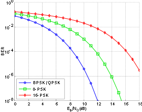
For example, in the case of QPSK modulation and AWGN channel, the BER as function of the Eb/N0 is given by:
 .
.
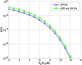
People usually plot the BER curves to describe the functionality of a digital communication system. In optical communication, BER(dB) vs. Received Power(dBm) is usually used; while in wireless communication, BER(dB) vs. SNR(dB) is used.
Measuring the bit error ratio helps people choose the appropriate forward error correction
codes. Since most such codes correct only bit-flips, but not bit-insertions or bit-deletions, the Hamming distance
metric is the appropriate way to measure the number of bit errors. Many FEC coders also continuously measure the current BER.
A more general way of measuring the number of bit errors is the Levenshtein distance
.
The Levenshtein distance measurement is more appropriate for measuring raw channel performance before frame synchronization
, and when using error correction codes designed to correct bit-insertions and bit-deletions, such as Marker Codes and Watermark Codes.
 . Considering a bipolar NRZ transmission, we have
 for a "1" and
  for a "0". Each of
  and
and  has a period of
  .
.
Knowing that the noise has a bilateral spectral density ,
,
 is
is 
and is
is  .
.
Returning to BER, we have the likelihood of a bit misinterpretation .
.
 and
and 
where is the threshold of decision, set to 0 when
  .
.
We can use the average energy of the signal to find the final expression :
±§
A BERT typically consists of a test pattern generator and a receiver that can be set to the same pattern. They can be used in pairs, with one at either end of a transmission link, or singularly at one end with a loopback
at the remote end. BERTs are typically stand-alone specialised instruments, but can be Personal Computer
based. In use, the number of errors, if any, are counted and presented as a ratio such as 1 in 1,000,000, or 1 in 1e06.
The main building blocks of a BERT are:
Bit
A bit is the basic unit of information in computing and telecommunications; it is the amount of information stored by a digital device or other physical system that exists in one of two possible distinct states...
s of a data stream
Data stream
In telecommunications and computing, a data stream is a sequence of digitally encoded coherent signals used to transmit or receive information that is in the process of being transmitted....
over a communication channel that have been altered due to noise, interference
Interference (communication)
In communications and electronics, especially in telecommunications, interference is anything which alters, modifies, or disrupts a signal as it travels along a channel between a source and a receiver. The term typically refers to the addition of unwanted signals to a useful signal...
, distortion
Distortion
A distortion is the alteration of the original shape of an object, image, sound, waveform or other form of information or representation. Distortion is usually unwanted, and often many methods are employed to minimize it in practice...
or bit synchronization errors.
The bit error rate or bit error ratio (BER) is the number of bit errors divided by the total number of transferred bits during a studied time interval. BER is a unitless performance measure, often expressed as a percentage
Percentage
In mathematics, a percentage is a way of expressing a number as a fraction of 100 . It is often denoted using the percent sign, “%”, or the abbreviation “pct”. For example, 45% is equal to 45/100, or 0.45.Percentages are used to express how large/small one quantity is, relative to another quantity...
.
The bit error probability pe is the expectation value of the BER. The BER can be considered as an approximate estimate of the bit error probability. This estimate is accurate for a long time interval and a high number of bit errors.
Example
As an example, assume this transmitted bit sequence:0 1 1 0 0 0 1 0 1 1,
and the following received bit sequence:
0 0 1 0 1 0 1 0 0 1,
The number of bit errors (the underlined bits) is in this case 3. The BER is 3 incorrect bits divided by 10 transferred bits, resulting in a BER of 0.3 or 30%.
Packet error rate
The packet error rate (PER) is the number of incorrectly received data packets divided by the total number of received packets. A packet is declared incorrect if at least one bit is erroneous. The expectation value of the PER is denoted packet error probability pp, which for a data packet length of N bits can be expressed as,assuming that the bit errors are independent of each other. For small bit error probabilities, this is approximately
Similar measurements can be carried out for the transmission of frames, block
Block (data storage)
In computing , a block is a sequence of bytes or bits, having a nominal length . Data thus structured are said to be blocked. The process of putting data into blocks is called blocking. Blocking is used to facilitate the handling of the data-stream by the computer program receiving the data...
s, or symbols.
Factors affecting the BER
In a communication system, the receiver side BER may be affected by transmission channel noise, interferenceInterference (communication)
In communications and electronics, especially in telecommunications, interference is anything which alters, modifies, or disrupts a signal as it travels along a channel between a source and a receiver. The term typically refers to the addition of unwanted signals to a useful signal...
, distortion
Distortion
A distortion is the alteration of the original shape of an object, image, sound, waveform or other form of information or representation. Distortion is usually unwanted, and often many methods are employed to minimize it in practice...
, bit synchronization problems, attenuation
Attenuation
In physics, attenuation is the gradual loss in intensity of any kind of flux through a medium. For instance, sunlight is attenuated by dark glasses, X-rays are attenuated by lead, and light and sound are attenuated by water.In electrical engineering and telecommunications, attenuation affects the...
, wireless multipath fading
Fading
In wireless communications, fading is deviation of the attenuation that a carrier-modulated telecommunication signal experiences over certain propagation media. The fading may vary with time, geographical position and/or radio frequency, and is often modelled as a random process. A fading channel...
, etc.
The BER may be improved by choosing a strong signal strength (unless this causes cross-talk and more bit errors), by choosing a slow and robust modulation
Modulation
In electronics and telecommunications, modulation is the process of varying one or more properties of a high-frequency periodic waveform, called the carrier signal, with a modulating signal which typically contains information to be transmitted...
scheme or line coding scheme, and by applying channel coding schemes such as redundant forward error correction
Forward error correction
In telecommunication, information theory, and coding theory, forward error correction or channel coding is a technique used for controlling errors in data transmission over unreliable or noisy communication channels....
codes.
The transmission BER is the number of detected bits that are incorrect before error correction, divided by the total number of transferred bits (including redundant error codes). The information BER, approximately equal to the decoding error probability, is the number of decoded bits that remain incorrect after the error correction, divided by the total number of decoded bits (the useful information). Normally the transmission BER is larger than the information BER. The information BER is affected by the strength of the forward error correction code.
Analysis of the BER
The BER may be analyzed using stochastic computer simulations. If a simple transmission channel model and data source model is assumed, the BER may also be calculated analytically. An example of such a data source model is the Bernoulli source.Examples of such simple channel models are:
- Binary symmetric channelBinary symmetric channelA binary symmetric channel is a common communications channel model used in coding theory and information theory. In this model, a transmitter wishes to send a bit , and the receiver receives a bit. It is assumed that the bit is usually transmitted correctly, but that it will be "flipped" with a...
(used in analysis of decoding error probability in case of non-bursty bit errorsError burstIn telecommunication, a burst error or error burst is a contiguous sequence of symbols, received over a data transmission channel, such that the first and last symbols are in error and there exists no contiguous subsequence of m correctly received symbols within the error burst.The integer...
on the transmission channel) - Additive white gaussian noiseAdditive white Gaussian noiseAdditive white Gaussian noise is a channel model in which the only impairment to communication is a linear addition of wideband or white noise with a constant spectral density and a Gaussian distribution of amplitude. The model does not account for fading, frequency selectivity, interference,...
(AWGN) channel without fading.
A worst case scenario is a completely random channel, where noise totally dominates over the useful signal. This results in a transmission BER of 50% (provided that a Bernoulli binary data source and a binary symmetrical channel are assumed, see below).
Carrier-to-noise ratio
In telecommunications, the carrier-to-noise ratio, often written CNR or C/N, is the signal-to-noise ratio of a modulated signal. The term is used to distinguish the CNR of the radio frequency passband signal from the SNR of an analogue base band message signal after demodulation, for example an...
measure denoted Eb/N0, (energy per bit to noise power spectral density ratio), or Es/N0 (energy per modulation symbol to noise spectral density).
For example, in the case of QPSK modulation and AWGN channel, the BER as function of the Eb/N0 is given by:
.People usually plot the BER curves to describe the functionality of a digital communication system. In optical communication, BER(dB) vs. Received Power(dBm) is usually used; while in wireless communication, BER(dB) vs. SNR(dB) is used.
Measuring the bit error ratio helps people choose the appropriate forward error correction
Forward error correction
In telecommunication, information theory, and coding theory, forward error correction or channel coding is a technique used for controlling errors in data transmission over unreliable or noisy communication channels....
codes. Since most such codes correct only bit-flips, but not bit-insertions or bit-deletions, the Hamming distance
Hamming distance
In information theory, the Hamming distance between two strings of equal length is the number of positions at which the corresponding symbols are different...
metric is the appropriate way to measure the number of bit errors. Many FEC coders also continuously measure the current BER.
A more general way of measuring the number of bit errors is the Levenshtein distance
Levenshtein distance
In information theory and computer science, the Levenshtein distance is a string metric for measuring the amount of difference between two sequences...
.
The Levenshtein distance measurement is more appropriate for measuring raw channel performance before frame synchronization
Frame synchronization
While receiving a stream of framed data, frame synchronization is the process by which incoming frame alignment signals, i.e., distinctive bit sequences , are identified, i.e., distinguished from data bits, permitting the data bits within the frame to be extracted for decoding or retransmission...
, and when using error correction codes designed to correct bit-insertions and bit-deletions, such as Marker Codes and Watermark Codes.
Mathematical draft
The BER is the likelihood of a bit misinterpretation due to electrical noise. Considering a bipolar NRZ transmission, we have for a "1" and for a "0". Each of and has a period of .Knowing that the noise has a bilateral spectral density
, is and
is .Returning to BER, we have the likelihood of a bit misinterpretation
. and where
is the threshold of decision, set to 0 when .We can use the average energy of the signal
to find the final expression :±§
Bit error rate test
BERT or bit error rate test is a testing method for digital communication circuits that uses predetermined stress patterns consisting of a sequence of logical ones and zeros generated by a pseudorandom binary sequencer.A BERT typically consists of a test pattern generator and a receiver that can be set to the same pattern. They can be used in pairs, with one at either end of a transmission link, or singularly at one end with a loopback
Loopback
Loopback describes ways of routing electronic signals, digital data streams, or flows of items from their originating facility back to the source without intentional processing or modification...
at the remote end. BERTs are typically stand-alone specialised instruments, but can be Personal Computer
Personal computer
A personal computer is any general-purpose computer whose size, capabilities, and original sales price make it useful for individuals, and which is intended to be operated directly by an end-user with no intervening computer operator...
based. In use, the number of errors, if any, are counted and presented as a ratio such as 1 in 1,000,000, or 1 in 1e06.
Common types of BERT stress patterns
- PRBS (Pseudo Random binary sequence) – A pseudorandom binary sequencer of N Bits. These pattern sequences are used to measure jitterJitterJitter is the undesired deviation from true periodicity of an assumed periodic signal in electronics and telecommunications, often in relation to a reference clock source. Jitter may be observed in characteristics such as the frequency of successive pulses, the signal amplitude, or phase of...
and eye mask of TX-Data in electrical and optical data links. - QRSS (Quasi Random Signal Source) – A pseudorandom binary sequencer which generates every combination of a 20-bit word, repeats every 1,048,575 bits, and suppresses consecutive zeros to no more than 14. It contains high-density sequences, low-density sequences, and sequences that change from low to high and vice versa. This pattern is also the standard pattern used to measure jitter.
- 3 in 24 – Pattern contains the longest string of consecutive zeros (15) with the lowest ones density (12.5%). This pattern simultaneously stresses minimum ones density and the maximum number of consecutive zeros. The D4D4 framing standardIn telecommunication, a D-4 is a framing standard for traditional time-division multiplexing, which standard describes user channels multiplexed onto a trunk that has been segmented into 24 bytes of 8 bits each....
frame format of 3 in 24 may cause a D4 Yellow Alarm for frame circuits depending on the alignment of one bits to a frame. - 1:7 – Also referred to as “1 in 8”. It has only a single one in an 8-bit repeating sequence. This pattern stresses the minimum ones density of 12.5% and should be used when testing facilities set for B8ZS coding as the 3 in 24 pattern increases to 29.5% when converted to B8ZS.
- Min/Max – Pattern rapid sequence changes from low density to high density. Most useful when stressing the repeater’s ALBO feature.
- All Ones (or Mark) – A pattern composed of ones only. This pattern causes the repeater to consume the maximum amount of power. If DC to the repeater is regulated properly, the repeater will have no trouble transmitting the long ones sequence. This pattern should be used when measuring span power regulation. An unframed all ones pattern is used to indicate an AISAlarm indication signalAlarm indication signal is a signal transmitted by an intermediate element of a multi-node transport circuit that is part of a concatenated telecommunications system to alert the receiving end of the circuit that a segment of the end-to-end link has failed at a logical or physical level, even if...
(also known as a Blue Alarm). - All Zeros – A pattern composed of zeros only. It is effective in finding equipment misoptioned for AMI, such as fiber/radio multiplex low-speed inputs.
- Alternating 0s and 1s - A pattern composed of alternating ones and zeroes.
- 2 in 8 – Pattern contains a maximum of four consecutive zeros. It will not invoke a B8ZS sequence because eight consecutive zeros are required to cause a B8ZS substitution. The pattern is effective in finding equipment misoptioned for B8ZS.
- Bridgetap - Bridge tapBridge tapBridged tap or bridge tap is a long-used method of cabling for telephone lines. One cable pair will "appear" in several different terminal locations . This allows the telephone company to use or "assign" that pair to any subscriber near those terminal locations. Once that customer disconnects,...
s within a span can be detected by employing a number of test patterns with a variety of ones and zeros densities. This test generates 21 test patterns and runs for 15 minutes. If a signal error occurs, the span may have one or more bridge taps. This pattern is only effective for T1 spans that transmit the signal raw. Modulation used in HDSL spans negates the Bridgetap patterns' ability to uncover bridge taps. - Multipat - This test generates 5 commonly used test patterns to allow DS1Digital Signal 1Digital signal 1 is a T-carrier signaling scheme devised by Bell Labs. DS1 is a widely used standard in telecommunications in North America and Japan to transmit voice and data between devices. E1 is used in place of T1 outside North America, Japan, and South Korea...
span testing without having to select each test pattern individually. Patterns are: All Ones, 1:7, 2 in 8, 3 in 24, and QRSS. - T1-DALY and 55 OCTET - Each of these patterns contain fifty-five (55), eight bit octets of data in a sequence that changes rapidly between low and high density. These patterns are used primarily to stress the ALBO and equalizer circuitry but they will also stress timing recovery. 55 OCTET has fifteen (15) consecutive zeroes and can only be used unframed without violating ones density requirements. For framed signals, the T1-DALY pattern should be used. Both patterns will force a B8ZS code in circuits optioned for B8ZS.
Bit error rate tester
A bit error rate tester (BERT), also known as a bit error ratio tester or bit error rate test solution (BERTs) is electronic test equipment used to test the quality of signal transmission of single components or complete systems.The main building blocks of a BERT are:
- Pattern GeneratorDigital pattern generatorA digital pattern generator is a piece of electronic test equipment or software used to generate digital electronics stimuli. Digital electronics stimuli are a specific kind of electrical waveform varying between two conventional voltages that correspond to two logic states...
, which transmits a defined test pattern to the DUTDevice under testDevice under test , also known as unit under test , is a term commonly used to refer to a manufactured product undergoing testing.-In semiconductor testing:...
or test system - Error detector connected to the DUT or test system, to count the errors generated by the DUT or test system
- Clock signal generator to synchronize the pattern generator and the error detector
- Digital communication analyser is optional to display the transmitted or received signal
- Electrical-optical converter and optical-electrical converter for testing optical communication signals.