

STEP-NC
Encyclopedia
Machine tool
A machine tool is a machine, typically powered other than by human muscle , used to make manufactured parts in various ways that include cutting or certain other kinds of deformation...
control language that extends the ISO 10303 STEP
ISO 10303
ISO 10303 is an ISO standard for the computer-interpretable representation and exchange of product manufacturing information. Its official title is: Automation systems and integration — Product data representation and exchange...
standards with the machining model in ISO 14649, adding geometric dimension and tolerance
Geometric dimensioning and tolerancing
Geometric dimensioning and tolerancing is a system for defining and communicating engineering tolerances. It uses a symbolic language on engineering drawings and computer-generated three-dimensional solid models for explicitly describing nominal geometry and its allowable variation...
data for inspection, and the STEP PDM
Product Data Management
Product data management is the business function often within product lifecycle management that is responsible for the creation, management and publication of product data...
model for integration into the wider enterprise. The combined result has been standardized as ISO 10303-238 (also known as AP238).
STEP-NC was designed to replace ISO 6983/RS274D G-codes
G-code
G-code is the common name for the most widely used computer numerical control programming language, which has many implementations. Used mainly in automation, it is part of computer-aided engineering. G-code is sometimes called G programming language...
with a modern, associative protocol that connects computer numerical controlled (CNC) process data to a product description of the part being machined.
A STEP-NC program can use the full range of geometric constructs from the STEP standard to communicate device-independent toolpaths to the CNC. It can provide CAM
Computer-aided manufacturing
Computer-aided manufacturing is the use of computer software to control machine tools and related machinery in the manufacturing of workpieces. This is not the only definition for CAM, but it is the most common; CAM may also refer to the use of a computer to assist in all operations of a...
operational descriptions and STEP CAD geometry
Boundary representation
In solid modeling and computer-aided design, boundary representation—often abbreviated as B-rep or BREP—is a method for representing shapes using the limits...
to the CNC so workpieces, stock, fixtures and cutting tool shapes can be visualized and analyzed in the context of the toolpaths. STEP GD&T information can also be added to enable quality measurement on the control, and CAM-independent volume removal features may be added to facilitate regeneration and modification of the toolpaths before or during machining for closed loop manufacturing.
Motivation
STEP-NC allows more information about the machining process to be sent to the machine control and adds new information about the product being machined. This "Smart Data for Smart Machining" enables applications such as the following:
- Toolpath descriptions that are portable and independent of machine geometry.
- Visual process, to show toolpaths in context of the machine and workpiece, and eliminate drawings.
- On-Machine Simulation, to check for gouges, machine interference and other undesired behavior.
- Simplified Inspection, with linked tolerances, on-machine probes and inspection workplans tied to part tolerances.
- Feed and Speed Optimization, using tolerances, cross section information, sensor data.
- Associativity so feedback can be sent from manufacturing back to design.
Capabilities
Milling machine
A milling machine is a machine tool used to machine solid materials. Milling machines are often classed in two basic forms, horizontal and vertical, which refers to the orientation of the main spindle. Both types range in size from small, bench-mounted devices to room-sized machines...
and turning
Turning
Turning is the process whereby a single point cutting tool is parallel to the surface. It can be done manually, in a traditional form of lathe, which frequently requires continuous supervision by the operator, or by using a computer controlled and automated lathe which does not. This type of...
, and extensions for other technologies under development (see Future Work).
- Product Description
- Workpiece, PDM and Product GeometryBoundary representationIn solid modeling and computer-aided design, boundary representation—often abbreviated as B-rep or BREP—is a method for representing shapes using the limits...
- Manufacturing FeaturesFeature recognitionThe term "feature" does not imply the same meaning in different engineering disciplines. This has resulted in several ambiguous definitions for feature. A feature, in computer-aided design software, can be called a region of a part with some interesting geometric or topological patterns...
- Dimensions and Tolerances
- Measures and Part Properties
- Workpiece, PDM and Product Geometry
- General Process Description
- Project
- Executable
- Operation
- Toolpath
- Technology-Specific Process Description
- Operations and cutting tools for milling
- Operations and cutting tools for turning
- Operations and devices for inspectionCoordinate-measuring machineA coordinate measuring machine is a device for measuring the physical geometrical characteristics of an object. This machine may be manually controlled by an operator or it may be computer controlled. Measurements are defined by a probe attached to the third moving axis of this machine...
STEP-NC can exchange the explicit toolpath descriptions in use today, and add part, stock, and fixture geometry, a description of the tools, geometric dimensions and tolerances, and PDM information. A STEP-NC file is difficult to edit by hand because it contains geometry descriptions but for large programs the file size can be smaller because STEP-NC uses a compressed
ZIP (file format)
Zip is a file format used for data compression and archiving. A zip file contains one or more files that have been compressed, to reduce file size, or stored as is...
XML format instead of ASCII codes.
History
STEP-NC is not the first attempt at providing better quality information to a CNC. The EIA 494 Basic Control Language (BCL) defined a control language that was portable and had toolpaths independent of machine geometry, but did not contain any of the other product model information found in STEP-NC.The core of STEP-NC is the ISO 14649 model for CNC control developed
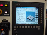
by European ESPRIT and IMS STEP-NC projects begun in 1999. These were led by Siemens with contributions from the University of Aachen and the University of Stuttgart in Germany, Komatsu and FANUC in Japan, Heidenhain in Switzerland, and the Pohang University of Science and Technology in Korea. Models for the control of CNC milling and turning machines were published in 2005, and draft models exist for EDM
Electrical discharge machining
Electric discharge machining , sometimes colloquially also referred to as spark machining, spark eroding, burning, die sinking or wire erosion, is a manufacturing process whereby a desired shape is obtained using electrical discharges...
and contour cutting.
Integration of the CNC model into STEP to produce ISO 10303-238 was done in the United States, under the NIST ATP
Advanced Technology Program
The NIST Advanced Technology Program is a United States Government program designed to simulate early stage advanced technology development that would otherwise not be fundable.ATP unique in that it is designed for early stage research in industry, not academia, though it...
Model Driven Intelligent Control of Manufacturing project, led by STEP Tools, Inc. with an industrial review board (IRB) consisting of Fortune 500 companies, CAD and CAM software developers, machine tool manufacturers, job shops and industry experts. STEP-NC AP238 was published in 2007.
In 2005 the OMAC STEP-NC Working Group hosted an AP238 testing forum in Orlando to demonstrate 5-axis parts machined using AP238 CC1 machine independent toolpaths. Four CAD/CAM systems produced AP238 machining programs for milling a 5-axis test part (an NAS 979 circle/diamond/square with an inverted NAS 979 cone test in the center). Each run on a pair of CNCs configured for completely different machine geometries (AB tool tilt vs. BC table tilt). In addition, Boeing cut parts on a variety of machines at their Tulsa facility and a machine at NIST in Gaithersburg.
In June 2006, a live 5-axis STEP-NC machining demonstration was hosted by Airbus at the Université Paul Sabatier Laboratoire de Génie mécanique in Toulouse.
Further machining and measurement demonstrations were conducted in Ibusuki Japan in 2007.
On March 10–12, 2008, the STEP Manufacturing team (ISO TC184 SC4 WG3 T24) met in Sandviken and Stockholm, Sweden to demonstrate use of STEP-NC for feed and speed optimization, high-speed machining, tolerance-driven tool compensation and traceability. The participants in the demonstrations included Airbus/Univ. Bordeaux, Boeing, Eurostep, KTH Royal Institute of Technology, NIST, Sandvik Coromant, Scania, STEP Tools, and Univ. of Vigo.
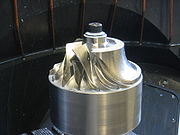
On October 1–2, 2008, the STEP Manufacturing team met at the Connecticut Center for Advanced Technology, in Hartford, Connecticut to demonstrate closed-loop machining, feed optimization, and measurement using STEP-NC. The highlight of the meeting was the live 5-axis machining of a titanium impeller. Participants in the machining demonstration and other activities included Boeing, Connecticut Center for Advanced Technology, Concepts NRec, DMG, KTH Royal Institute of Technology, Mitutoyo, NIST, Sandvik Coromant, Scania, Siemens, and STEP Tools.
These participants and others continue to hold STEP-NC international implementation and testing events on a roughly six month cycle. The demonstrations in 2009 focused on machining a Mold part at multiple sites from the same AP238 data including one part machined on a FANUC-developed STEP-NC control. At a meeting in Seattle the parts were then measured for accuracy using a CMM probe and a laser scanner.
In the first half of 2010, the testing activity focused on tool wear management and machining a part in multiple setups with multiple alternate machining plans for 3, 4 and 5-axis machining. The new test part was a gear box that must be machined on all six sides. The tool wear and consequent machine loads were predicted from the STEP-NC data and verified using a dynamometer
Dynamometer
A dynamometer or "dyno" for short, is a device for measuring force, moment of force , or power. For example, the power produced by an engine, motor or other rotating prime mover can be calculated by simultaneously measuring torque and rotational speed .A dynamometer can also be used to determine...
. In the second half of 2010, the testing forum applied STEP-NC to setup compensation with on-machine measurement of part and fixture datums using a FaroArm portable measurement device.
Future Work
Work on extending and integrating STEP-NC with the manufacturing enterprise takes place in the ISO TC184/SC4/WG3/T24 STEP Manufacturing Team. This group also works on extensions and refinements discovered during testing. A series of traceability extensions have been proposed for linking STEP-NC machining programs with sensor feedback and machine state information during execution.
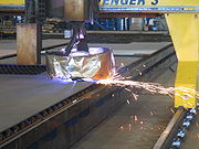
The National Shipbuilding Research Program (NSRP) has also hosted work to implement a prototype that connects a shipyard design system to a plate cutting using STEP-NC. This work involved extending STEP-NC to steel plate cutting and marking using lasers
Laser cutting
Laser cutting is a technology that uses a laser to cut materials, and is typically used for industrial manufacturing applications, but is also starting to be used by schools, small businesses and hobbyists. Laser cutting works by directing the output of a high-power laser, by computer, at the...
and plasma torches
Plasma cutting
Plasma cutting is a process that is used to cut steel and other metals of different thicknesses using a plasma torch...
.