
Repulsion motor
Encyclopedia
A repulsion motor is a type of electric motor
for use on alternating current
. It was formerly used as a traction motor
for electric train
s but has been superseded by other types of motors and is now only of historical interest. Repulsion motors are classified under Single Phase motors. In magnetic repulsion motors the stator windings are connected directly to the ac power supply and the rotor is connected to commutator and brush assembly, similar to that of a DC armature.
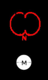
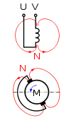
The principle of torque production in a repulsion motor could be explained as follows. Figure 1 shows a two pole motor with its magnetic axis vertical. An armature having commutator which is short circuited through the brushes, is placed in the magnetic field. When the stator winding is connected to an AC supply, it produces an alternating magnetic field. Assume that at one instant, a north pole at the top and a south pole at the bottom are produced by this alternating magnetic field. Because of the changing magnetic field, a voltage will be induced in all the rotor conductors by transformer action. The direction of current in the conductors will be in accordance with Lenz's law such that they create a north pole at the top just below the stator north pole, and a south pole at the bottom just at the top of the stator south pole to oppose the induction action. Hence the stator poles and the rotor poles will oppose each other in the same line. There will, therefore, be no torque developed due to the absence of the tangential component of the torque.
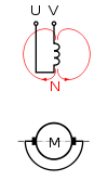
Let us assume that the short-circuited brush-axis is moved to a position as in Figure 2. Due to this brush position, the magnetic axis of the armature is no longer co-linear with respect to the vertical axis of the main poles.
It will be now along the axis KK with north and south poles shifted around by an angle A° depending upon the shifting of the brushes. In this position, the direction of current in the conductors 1,2,3 and 13,14,15 is reversed, and hence, the armature becomes an electromagnet having the north (N) and south (S) poles in the KK axis just an angle of A° from the main magnetic axis. Now there is a condition that the rotor north pole will be repelled by the main north pole, so that the torque could be developed in the rotor. Now due to the repulsion action between stator and the rotor poles, the rotor will rotating in a clockwise direction. As the motor torque is due to repulsion action, this motor is named as repulsion motor.
and a rotor
but there is no electrical connection between the two and the rotor current is generated by induction
. The rotor winding is connected to a commutator
which is in contact with a pair of short-circuited
brushes
which can be moved to change their angular position relative to an imaginary line drawn through the axis of the stator. The motor can be started, stopped and reversed, and the speed can be varied, simply by changing the angular position of the brushes.
Most commutator motors are limited to about 1,500 volt
s because higher voltages give rise to a risk of arcing across the commutator. Repulsion motors can be used at higher voltages because the rotor circuit is not electrically connected to the supply..
Now let us understand the theory behind the production of rotating magnetic field using the repulsion principle.
Repulsion motors are based on the principle of repulsion between two magnetic fields. Consider a 2-pole salient pole motor with vertical magnetic axis. For better understanding of the principle here we use a salient pole type instead of non-salient pole type, since the basic functioning of both the construction is same. The armature is connected to commutator and brush. The brushes are short circuited using a low-resistance jumper.
Now when alternating current is supplied to field or stator winding, it induces an emf in the armature. The direction of alternating current is such that it creates north pole at the top and south pole at the bottom. The direction of induced emf is given by Lenz law, according to which the direction of induced emf is so as to oppose the cause producing it. Now the induced emf induces the current in the armature conductors. The direction of induced current in the armature conductors depends on the position of the brush.
If the brush axis is along the direction of the field (or) if the brush axis is collinear with the magnetic field, the armature behaves like an electromagnet and so an N-pole is formed directly below the N-pole of the stator and S-pole is formed directly above the S-pole of the stator. Now the net torque at this condition is zero. Both the N-poles repel each other and Both the S-poles repel each other. The two repulsion forces are in direct opposition to each other and hence no torque will be developed in this condition.
In other words we can say that the torque developed in four quadrants around the brushes neutralizes each other and hence the net torque is 0.
In the above condition the brush axis is along the axis of the magnetic field. Now let us consider that the brushes are shifted through 90 degree, so that the magnetic axis is perpendicular to the brush axis. Since the brushes are shifted through 90 degree, the coils undergoing short circuit also changes. So apart from the coils undergoing short circuit, the voltage induced in the other coils between the brush terminals gets neutralized and the net voltage is zero. Since there is no induced emf, there is no current in the circuit and hence there is net torque develop in the circuit is zero. In other words no torque will be developed in the circuit.
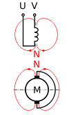
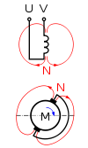
Now consider a situation where the brush axis is neither along the magnetic axis nor perpendicular to the magnetic axis. The brush axis is displaced at an angle α to the magnetic axis. Now a net voltage is induced in the brush terminals which will produce current in the armature. Due to the current in the armature circuit, it will produce its own magnetic field with North and South poles. But in this condition North Pole is not directly under the north pole of Magnetic axis and South Pole is not directly above the South Pole of magnetic axis. The poles of armature are slightly displaced from that of the poles of the stator (or) the main magnetic field.
So during this condition the N-pole of main field will repel the N-pole of the rotor field and similarly S-pole of main field will repel the S-pole of the rotor field. So the rotor starts rotating in a particular direction. The direction of rotation of motor is determined by the position of the brushes with respect to the main magnetic field or magnetic field of the stator. In other words the direction of rotation is determined by the direction of brush shift. If the brushes are shifted clockwise from main magnetic axis, then the motor will rotate in clockwise direction. If the brushes are shifted counter clockwise from the main magnetic axis, then the motor rotates in anti clockwise (or) counter clockwise direction.
The value of starting torque of repulsion motors is determined by the amount of brush shift α from the main magnetic axis. The maximum torque is obtained for the brush shift of 45 degrees. In other word maximum torque occurs when α=45 degrees. Brush shift also helps in speed control of repulsion motors.
/speed characteristics of the motor as closely as possible to the service it was required to provide.
1. Repulsion motor
2. Compensated-repulsion motor
3. Repulsion-Start, induction-run motor
4. Repulsion-induction motor
motor is the original repulsion motor and is described in "Construction" above.
the motor is called as elihu thomson motor.
motor is similar to the Elihu Thomson type but has two pairs of short-circuited brushes—one fixed and one moveable. This allows very fine control of speed.
There are, again, two pairs of brushes but they are fixed at right angles to each other. One pair is short-circuited while the other pair is fed with variable-voltage alternating current
from tappings
on the secondary winding of a small transformer
. The primary winding of the transformer is in series
with the stator winding of the motor. This motor has the same torque/speed characteristics as an ordinary series-wound motor.
speed to 10% above. Starting torque is about 2.5 times full-load torque with twice full-load current.
Electric motor
An electric motor converts electrical energy into mechanical energy.Most electric motors operate through the interaction of magnetic fields and current-carrying conductors to generate force...
for use on alternating current
Alternating current
In alternating current the movement of electric charge periodically reverses direction. In direct current , the flow of electric charge is only in one direction....
. It was formerly used as a traction motor
Traction motor
Traction motor refers to an electric motor providing the primary rotational torque of a machine, usually for conversion into linear motion ....
for electric train
Electric train
Electric train may refer to:* Diesel-electric locomotive...
s but has been superseded by other types of motors and is now only of historical interest. Repulsion motors are classified under Single Phase motors. In magnetic repulsion motors the stator windings are connected directly to the ac power supply and the rotor is connected to commutator and brush assembly, similar to that of a DC armature.
Repulsion
| Idle | Short-circuit | Position for clockwise operation |
Position for counterclockwise operation |
|---|---|---|---|
 |
 |
 |
 |
The principle of torque production in a repulsion motor could be explained as follows. Figure 1 shows a two pole motor with its magnetic axis vertical. An armature having commutator which is short circuited through the brushes, is placed in the magnetic field. When the stator winding is connected to an AC supply, it produces an alternating magnetic field. Assume that at one instant, a north pole at the top and a south pole at the bottom are produced by this alternating magnetic field. Because of the changing magnetic field, a voltage will be induced in all the rotor conductors by transformer action. The direction of current in the conductors will be in accordance with Lenz's law such that they create a north pole at the top just below the stator north pole, and a south pole at the bottom just at the top of the stator south pole to oppose the induction action. Hence the stator poles and the rotor poles will oppose each other in the same line. There will, therefore, be no torque developed due to the absence of the tangential component of the torque.
Let us assume that the short-circuited brush-axis is moved to a position as in Figure 2. Due to this brush position, the magnetic axis of the armature is no longer co-linear with respect to the vertical axis of the main poles.
It will be now along the axis KK with north and south poles shifted around by an angle A° depending upon the shifting of the brushes. In this position, the direction of current in the conductors 1,2,3 and 13,14,15 is reversed, and hence, the armature becomes an electromagnet having the north (N) and south (S) poles in the KK axis just an angle of A° from the main magnetic axis. Now there is a condition that the rotor north pole will be repelled by the main north pole, so that the torque could be developed in the rotor. Now due to the repulsion action between stator and the rotor poles, the rotor will rotating in a clockwise direction. As the motor torque is due to repulsion action, this motor is named as repulsion motor.
Construction
The motor has a statorStator
The stator is the stationary part of a rotor system, found in an electric generator, electric motor and biological rotors.Depending on the configuration of a spinning electromotive device the stator may act as the field magnet, interacting with the armature to create motion, or it may act as the...
and a rotor
Rotor (electric)
The rotor is the non-stationary part of a rotary electric motor, electric generator or alternator, which rotates because the wires and magnetic field of the motor are arranged so that a torque is developed about the rotor's axis. In some designs, the rotor can act to serve as the motor's armature,...
but there is no electrical connection between the two and the rotor current is generated by induction
Electromagnetic induction
Electromagnetic induction is the production of an electric current across a conductor moving through a magnetic field. It underlies the operation of generators, transformers, induction motors, electric motors, synchronous motors, and solenoids....
. The rotor winding is connected to a commutator
Commutator (electric)
A commutator is a rotary electrical switch in certain types of electric motors or electrical generators that periodically reverses the current direction between the rotor and the external circuit. In a motor, it applies power to the best location on the rotor, and in a generator, picks off power...
which is in contact with a pair of short-circuited
Short circuit
A short circuit in an electrical circuit that allows a current to travel along an unintended path, often where essentially no electrical impedance is encountered....
brushes
Brush (electric)
A brush is a device which conducts current between stationary wires and moving parts, most commonly in a rotating shaft. Typical applications include electric motors, alternators and electric generators.-Etymology:...
which can be moved to change their angular position relative to an imaginary line drawn through the axis of the stator. The motor can be started, stopped and reversed, and the speed can be varied, simply by changing the angular position of the brushes.
Most commutator motors are limited to about 1,500 volt
Volt
The volt is the SI derived unit for electric potential, electric potential difference, and electromotive force. The volt is named in honor of the Italian physicist Alessandro Volta , who invented the voltaic pile, possibly the first chemical battery.- Definition :A single volt is defined as the...
s because higher voltages give rise to a risk of arcing across the commutator. Repulsion motors can be used at higher voltages because the rotor circuit is not electrically connected to the supply..
Principle
Principle Of Repulsion MotorsNow let us understand the theory behind the production of rotating magnetic field using the repulsion principle.
Repulsion motors are based on the principle of repulsion between two magnetic fields. Consider a 2-pole salient pole motor with vertical magnetic axis. For better understanding of the principle here we use a salient pole type instead of non-salient pole type, since the basic functioning of both the construction is same. The armature is connected to commutator and brush. The brushes are short circuited using a low-resistance jumper.
Now when alternating current is supplied to field or stator winding, it induces an emf in the armature. The direction of alternating current is such that it creates north pole at the top and south pole at the bottom. The direction of induced emf is given by Lenz law, according to which the direction of induced emf is so as to oppose the cause producing it. Now the induced emf induces the current in the armature conductors. The direction of induced current in the armature conductors depends on the position of the brush.
If the brush axis is along the direction of the field (or) if the brush axis is collinear with the magnetic field, the armature behaves like an electromagnet and so an N-pole is formed directly below the N-pole of the stator and S-pole is formed directly above the S-pole of the stator. Now the net torque at this condition is zero. Both the N-poles repel each other and Both the S-poles repel each other. The two repulsion forces are in direct opposition to each other and hence no torque will be developed in this condition.
In other words we can say that the torque developed in four quadrants around the brushes neutralizes each other and hence the net torque is 0.
In the above condition the brush axis is along the axis of the magnetic field. Now let us consider that the brushes are shifted through 90 degree, so that the magnetic axis is perpendicular to the brush axis. Since the brushes are shifted through 90 degree, the coils undergoing short circuit also changes. So apart from the coils undergoing short circuit, the voltage induced in the other coils between the brush terminals gets neutralized and the net voltage is zero. Since there is no induced emf, there is no current in the circuit and hence there is net torque develop in the circuit is zero. In other words no torque will be developed in the circuit.
Now consider a situation where the brush axis is neither along the magnetic axis nor perpendicular to the magnetic axis. The brush axis is displaced at an angle α to the magnetic axis. Now a net voltage is induced in the brush terminals which will produce current in the armature. Due to the current in the armature circuit, it will produce its own magnetic field with North and South poles. But in this condition North Pole is not directly under the north pole of Magnetic axis and South Pole is not directly above the South Pole of magnetic axis. The poles of armature are slightly displaced from that of the poles of the stator (or) the main magnetic field.
So during this condition the N-pole of main field will repel the N-pole of the rotor field and similarly S-pole of main field will repel the S-pole of the rotor field. So the rotor starts rotating in a particular direction. The direction of rotation of motor is determined by the position of the brushes with respect to the main magnetic field or magnetic field of the stator. In other words the direction of rotation is determined by the direction of brush shift. If the brushes are shifted clockwise from main magnetic axis, then the motor will rotate in clockwise direction. If the brushes are shifted counter clockwise from the main magnetic axis, then the motor rotates in anti clockwise (or) counter clockwise direction.
The value of starting torque of repulsion motors is determined by the amount of brush shift α from the main magnetic axis. The maximum torque is obtained for the brush shift of 45 degrees. In other word maximum torque occurs when α=45 degrees. Brush shift also helps in speed control of repulsion motors.
Types of Repulsion Motors
Types of repulsion motor are listed below under the names of their inventors. It is likely that the different types were developed to match the torqueTorque
Torque, moment or moment of force , is the tendency of a force to rotate an object about an axis, fulcrum, or pivot. Just as a force is a push or a pull, a torque can be thought of as a twist....
/speed characteristics of the motor as closely as possible to the service it was required to provide.
1. Repulsion motor
2. Compensated-repulsion motor
3. Repulsion-Start, induction-run motor
4. Repulsion-induction motor
Elihu Thomson
The Elihu ThomsonElihu Thomson
Elihu Thomson was an American engineer and inventor who was instrumental in the founding of major electrical companies in the United States, the United Kingdom and France.-Early life:...
motor is the original repulsion motor and is described in "Construction" above.
the motor is called as elihu thomson motor.
Deri
The DeriMiksa Déri
Miksa Déri was a Hungarian electrical engineer. He was, with his partners Károly Zipernowsky and Ottó Bláthy, co-inventor of the closed iron core transformer and the ZBD model AC electrical generator....
motor is similar to the Elihu Thomson type but has two pairs of short-circuited brushes—one fixed and one moveable. This allows very fine control of speed.
Latour-Winter-Eichberg
This is the "compensated" repulsion motor devised independently by Latour and by Winter-Eichberg.There are, again, two pairs of brushes but they are fixed at right angles to each other. One pair is short-circuited while the other pair is fed with variable-voltage alternating current
Alternating current
In alternating current the movement of electric charge periodically reverses direction. In direct current , the flow of electric charge is only in one direction....
from tappings
Tap (transformer)
A transformer tap is a connection point along a transformer winding that allows a certain number of turns to be selected. This means, a transformer with a variable turns ratio is produced, enabling voltage regulation of the output...
on the secondary winding of a small transformer
Transformer
A transformer is a device that transfers electrical energy from one circuit to another through inductively coupled conductors—the transformer's coils. A varying current in the first or primary winding creates a varying magnetic flux in the transformer's core and thus a varying magnetic field...
. The primary winding of the transformer is in series
Series and parallel circuits
Components of an electrical circuit or electronic circuit can be connected in many different ways. The two simplest of these are called series and parallel and occur very frequently. Components connected in series are connected along a single path, so the same current flows through all of the...
with the stator winding of the motor. This motor has the same torque/speed characteristics as an ordinary series-wound motor.
Atkinson
The Atkinson motor has two stator coils at right angles to each other. Speed control (by brush-shifting) is possible from 75% below synchronousSynchronization (alternating current)
-Electricity generation:Electricity generation requires the connection of large numbers of alternators in parallel and additional alternators must be switched in when demand rises....
speed to 10% above. Starting torque is about 2.5 times full-load torque with twice full-load current.
Repulsion-start induction motors
These were used where high starting torque was required. They started as repulsion motors, but once they were running at a sizable fraction of full speed, the brushes were lifted mechanically and all commutator bars were short-circuited together to create the equivalent of a squirrel-cage induction motor.See also
- Electric motor#AC motors
- SR Class CPSR Class CPThe Southern Railway gave the designation CP to the fleet of AC electric multiple units used on the former London, Brighton and South Coast Railway lines in the Crystal Palace area.-Construction:...
electric multiple unit - SR Class SLSR Class SLThe Southern Railway gave the designation SL to the fleet of AC overhead electric multiple units used on the South London Line. These had been built by the London, Brighton and South Coast Railway in 1909, but with the abandonment of the Elevated Electric service in 1928 they were converted to DC...
electric multiple unit
Sources
- The Electrical Year Book 1937, published by Emmott and Company Limited, Manchester, England, pp 79–82