

Cuk converter
Encyclopedia
The Ćuk converter is a type of DC-DC converter that has an output voltage magnitude that is either greater than or less than the input voltage magnitude.
The non-isolated Ćuk converter can only have opposite polarity between input and output. It uses a capacitor
as its main energy-storage component, unlike most other types of converters which use an inductor
. It is named after Slobodan Ćuk of the California Institute of Technology
, who first presented the design.

 A non-isolated Ćuk converter comprises two inductor
s, two capacitor
s, a switch (usually a transistor
), and a diode
. Its schematic can be seen in figure 1. It is an inverting converter, so the output voltage is negative with respect to the input voltage.
The capacitor C is used to transfer energy and is connected alternately to the input and to the output of the converter via the commutation of the transistor and the diode (see figures 2 and 3).
The two inductors L1 and L2 are used to convert respectively the input voltage source (Vi) and the output voltage source (Co) into current sources. Indeed, at a short time scale an inductor can be considered as a current source as it maintains a constant current. This conversion is necessary because if the capacitor were connected directly to the voltage source, the current would be limited only by (parasitic) resistance, resulting in high energy loss. Charging a capacitor with a current source (the inductor) prevents resistive current limiting and its associated energy loss.
As with other converters (buck converter
, boost converter
, buck-boost converter
) the Ćuk converter can either operate in continuous or discontinuous current mode. However, unlike these converters, it can also operate in discontinuous voltage mode (i.e., the voltage across the capacitor drops to zero during the commutation cycle).

This implies that the current through the inductors has to be the same at the beginning and the end of the commutation cycle. As the evolution of the current through an inductor is related to the voltage across it:

it can be seen that the average value of the inductor voltages over a commutation period have to be zero to satisfy the steady-state requirements.
If we consider that the capacitors C and Co are large enough for the voltage ripple across them to be negligible, the inductor voltages become:
The converter operates in on-state from t=0 to t=D·T (D is the duty cycle
), and in off state from D·T to T (that is, during a period equal to (1-D)·T). The average values of VL1 and VL2 are therefore:


As both average voltage have to be zero to satisfy the steady-state conditions we can write, using the last equation:

So the average voltage across L1 becomes:

Which can be written as:

It can be seen that this relation is the same as that obtained for the Buck-boost converter
.
If this inductor is too small or below the "critical inductance", then the current will be discontinuous.
This state of operation is usually not studied too much depth, as it is not used beyond a demonstrating of why the minimum inductance is crucial.
The minimum inductance is given by:

Where is the switching frequency.
The transformer action between the inductors inside that component gives a coupled inductor Ćuk converter lower output ripple than a Ćuk converter using two independent discrete inductor components.
The non-isolated Ćuk converter can only have opposite polarity between input and output. It uses a capacitor
Capacitor
A capacitor is a passive two-terminal electrical component used to store energy in an electric field. The forms of practical capacitors vary widely, but all contain at least two electrical conductors separated by a dielectric ; for example, one common construction consists of metal foils separated...
as its main energy-storage component, unlike most other types of converters which use an inductor
Inductor
An inductor is a passive two-terminal electrical component used to store energy in a magnetic field. An inductor's ability to store magnetic energy is measured by its inductance, in units of henries...
. It is named after Slobodan Ćuk of the California Institute of Technology
California Institute of Technology
The California Institute of Technology is a private research university located in Pasadena, California, United States. Caltech has six academic divisions with strong emphases on science and engineering...
, who first presented the design.
Operating Principle
Inductor
An inductor is a passive two-terminal electrical component used to store energy in a magnetic field. An inductor's ability to store magnetic energy is measured by its inductance, in units of henries...
s, two capacitor
Capacitor
A capacitor is a passive two-terminal electrical component used to store energy in an electric field. The forms of practical capacitors vary widely, but all contain at least two electrical conductors separated by a dielectric ; for example, one common construction consists of metal foils separated...
s, a switch (usually a transistor
Transistor
A transistor is a semiconductor device used to amplify and switch electronic signals and power. It is composed of a semiconductor material with at least three terminals for connection to an external circuit. A voltage or current applied to one pair of the transistor's terminals changes the current...
), and a diode
Diode
In electronics, a diode is a type of two-terminal electronic component with a nonlinear current–voltage characteristic. A semiconductor diode, the most common type today, is a crystalline piece of semiconductor material connected to two electrical terminals...
. Its schematic can be seen in figure 1. It is an inverting converter, so the output voltage is negative with respect to the input voltage.
The capacitor C is used to transfer energy and is connected alternately to the input and to the output of the converter via the commutation of the transistor and the diode (see figures 2 and 3).
The two inductors L1 and L2 are used to convert respectively the input voltage source (Vi) and the output voltage source (Co) into current sources. Indeed, at a short time scale an inductor can be considered as a current source as it maintains a constant current. This conversion is necessary because if the capacitor were connected directly to the voltage source, the current would be limited only by (parasitic) resistance, resulting in high energy loss. Charging a capacitor with a current source (the inductor) prevents resistive current limiting and its associated energy loss.
As with other converters (buck converter
Buck converter
A buck converter is a step-down DC to DC converter. Its design is similar to the step-up boost converter, and like the boost converter it is a switched-mode power supply that uses two switches , an inductor and a capacitor....
, boost converter
Boost converter
A boost converter is a power converter with an output DC voltage greater than its input DC voltage. It is a class of switching-mode power supply containing at least two semiconductor switches and at least one energy storage element...
, buck-boost converter
Buck-boost converter
The buck–boost converter is a type of DC-to-DC converter that has an output voltage magnitude that is either greater than or less than the input voltage magnitude.Two different topologies are called buck–boost converter....
) the Ćuk converter can either operate in continuous or discontinuous current mode. However, unlike these converters, it can also operate in discontinuous voltage mode (i.e., the voltage across the capacitor drops to zero during the commutation cycle).
Continuous mode
In steady state, the energy stored in the inductors has to remain the same at the beginning and at the end of a commutation cycle. The energy in an inductor is given by:This implies that the current through the inductors has to be the same at the beginning and the end of the commutation cycle. As the evolution of the current through an inductor is related to the voltage across it:
it can be seen that the average value of the inductor voltages over a commutation period have to be zero to satisfy the steady-state requirements.
If we consider that the capacitors C and Co are large enough for the voltage ripple across them to be negligible, the inductor voltages become:
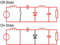
- in the off-state, inductor L1 is connected in series with Vi and C (see figure 2). Therefore
 . As the diode D is forward biased (we consider zero voltage drop), L2 is directly connected to the output capacitor. Therefore
- in the on-state, inductor L1 is directly connected to the input source. Therefore
 . Inductor L2 is connected in series with C and the output capacitor, so
The converter operates in on-state from t=0 to t=D·T (D is the duty cycle
Duty cycle
In engineering, the duty cycle of a machine or system is the time that it spends in an active state as a fraction of the total time under consideration....
), and in off state from D·T to T (that is, during a period equal to (1-D)·T). The average values of VL1 and VL2 are therefore:
As both average voltage have to be zero to satisfy the steady-state conditions we can write, using the last equation:
So the average voltage across L1 becomes:
Which can be written as:
It can be seen that this relation is the same as that obtained for the Buck-boost converter
Buck-boost converter
The buck–boost converter is a type of DC-to-DC converter that has an output voltage magnitude that is either greater than or less than the input voltage magnitude.Two different topologies are called buck–boost converter....
.
Discontinuous mode
Like all DC-DC converters Cuk converters rely on the ability of the inductors in the circuit to provide continuous current, in much the same way a capacitor in a rectifier filter provides continuous voltage.If this inductor is too small or below the "critical inductance", then the current will be discontinuous.
This state of operation is usually not studied too much depth, as it is not used beyond a demonstrating of why the minimum inductance is crucial.
The minimum inductance is given by:
Where
is the switching frequency.Inductor coupling
Instead of using two discrete inductor components, many designers implement a coupled inductor Ćuk converter, using a single magnetic component that includes both inductors on the same core.The transformer action between the inductors inside that component gives a coupled inductor Ćuk converter lower output ripple than a Ćuk converter using two independent discrete inductor components.