

Composite image filter
Encyclopedia
A composite image filter is an electronic filter
consisting of multiple image filter sections of two or more different types.
The image method of filter design determines the properties of filter sections by calculating the properties they have in an infinite chain of such sections. In this, the analysis parallels transmission line
theory on which it is based. Filters designed by this method are called image parameter filters, or just image filters. An important parameter of image filters is their image impedance
, the impedance of an infinite chain of identical sections.
The basic sections are arranged into a ladder network of several sections, the number of sections required is mostly determined by the amount of stopband
rejection required. In its simplest form, the filter can consist entirely of identical sections. However, it is more usual to use a composite filter of two or three different types of section to improve different parameters best addressed by a particular type. The most frequent parameters considered are stopband rejection, steepness of the filter skirt (transition band
) and impedance matching to the filter terminations.
Image filters are linear filter
s and are invariably also passive
in implementation.
, who were interested in developing filtering that could be used with the multiplexing
of many telephone channels on to a single cable. The researchers involved in this work and their contributions are briefly listed below;
of a section in an infinite chain of identical sections. This can be shown to be equivalent to the performance of a section terminated in its image impedances. The image method, therefore, relies on each filter section being terminated with the correct image impedance. This is easy enough to do with the internal sections of a multiple section filter, because it is only necessary to ensure that the sections facing the one in question have identical image impedances. However, the end sections are a problem. They will usually be terminated with fixed resistance
s that the filter cannot match perfectly except at one specific frequency. This mismatch leads to multiple reflections at the filter terminations and at the junctions between sections. These reflections result in the filter response
deviating quite sharply from the theoretical, especially near the cut-off frequency.
The requirement for better matching to the end impedances is one of the main motivations for using composite filters. A section designed to give good matching is used at the ends but something else (for instance stopband
rejection or passband
to stopband transition) is designed for the body of the filter.
s for low-pass
sections. These prototypes may be scaled and transformed to the desired frequency bandform (low-pass, high-pass
, band-pass
or band-stop
).
The smallest unit of an image filter is an L half-section. Because the L section is not symmetrical, it has different image impedances ( ) on each side. These are denoted
  and
and  . The T and the Π in the suffix refer to the shape of the filter section that would be formed if two half sections were to be connected back-to-back. T and Π are the smallest symmetrical sections that can be constructed, as shown in diagrams in the topology chart (below). Where the section in question has an image impedance different from the general case a further suffix is added identifying the section type, for instance
  .
.
or k-type filter section is the basic image filter section. It is also the simplest circuit topology. The k-type has moderately fast transition from the passband to the stopband and moderately good stopband rejection.
or m-type filter section is a development of the k-type section. The most prominent feature of the m-type is a pole of attenuation just past the cut-off frequency inside the stopband. The parameter m (0
The m-type has a particularly fast cut-off, going from fully pass at the cut-off frequency to fully stop at the pole frequency. The cut-off can be made faster by moving the pole nearer to the cut-off frequency. This filter has the fastest cut-off of any filter design; note that the fast transition is achieved with just a single section, there is no need for multiple sections. The drawback with m-type sections is that they have poor stopband rejection past the pole of attenuation.
There is a particularly useful property of m-type filters with m=0.6. These have maximally flat image impedance in the passband. They are therefore good for matching in to the filter terminations, in the passband at least, the stopband is another story.
There are two variants of the m-type section, series and shunt. They have identical transfer functions but their image impedances are different. The shunt half-section has an image impedance which matches on one side but has a different impedance,
  on the other. The series half-section matches
  on one side and has
  on the other.
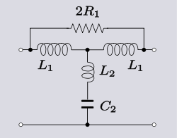
section has two independent parameters (m and m' ) that the designer can adjust. It is arrived at by double application of the m-derivation process. Its chief advantage is that it rather better at matching in to resistive end terminations than the k-type or m-type. The image impedance of a half-section is  on one side and a different impedance,
  on the other. Like the m-type, this section can be constructed as a series or shunt section and the image impedances will come in T and Π variants. Either a series construction is applied to a shunt m-type or a shunt construction is applied to a series m-type. The advantages of the mm
' -type filter are achieved at the expense of greater circuit complexity so it would normally only be used where it is needed for impedance matching purposes and not in the body of the filter.
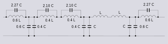
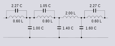
The transfer function of an mm'-type is the same as an m-type with m set to the product mm' . To choose values of m and m' for best impedance match requires the designer to choose two frequencies at which the match is to be exact, at other frequencies there will be some deviation. There is thus some leeway in the choice but Zobel suggests the values m=0.7230 and m' =0.4134 which give a deviation of the impedance of less than 2% over the useful part of the band. Since mm' =0.3, this section will also have a much faster cut-off than an m-type of m=0.6 which is an alternative for impedance matching.
It is possible to continue the m-derivation process repeatedly and produce mm'm
 Another variation on the m-type filter was described by Hendrik Bode. This filter uses as a prototype a mid-series m-derived filter and transforms this into a bridged-T topology with the addition of a bridging resistor. This section has the advantage of being able to place the pole of attenuation much closer to the cut-off frequency than the Zobel filter, which starts to fail to work properly with very small values of m because of inductor resistance. See equivalent impedance transforms for an explanation of its operation.
filters is that they have a constant resistance image impedance and for this reason are also known as constant resistance networks. Clearly, the Zobel network filter does not have a problem matching to its terminations and this is its main advantage. However, other filter types have steeper transfer functions and sharper cut-offs. In filtering applications, the main role of Zobel networks is as equalisation filters. Zobel networks are in a different group from other image filters. The constant resistance means that when used in combination with other image filter sections the same problem of matching arises as with end terminations. Zobel networks also suffer the disadvantage of using far more components than other equivalent image sections.
Sections at the beginning and end of the filter are often chosen for their impedance match in to the terminations rather than the shape of their frequency response. For this purpose, m-type sections of m = 0.6 are the most common choice. An alternative is mm'-type sections of m=0.7230 and m' =0.4134 although this type of section is rarely used. While it has several advantages noted below, it has the disadvantages of being more complex and also, if constant k sections are required in the body of the filter, it is then necessary to include m-type sections to interface the mm'-type to the k-types.
The inner sections of the filter are most commonly chosen to be constant k since these produce the greatest stopband attenuation. However, one or two m-type sections might also be included to improve the rate of fall from pass to stopband. A low value of m is chosen for m-types used for this purpose. The lower the value of m, the faster the transition, while at the same time, the stopband attenuation becomes less, increasing the need to use extra k-type sections as well. An advantage of using mm'-types for impedance matching is that these type of end sections will have a fast transition anyway (much more so than m=0.6 m-type) because mm' =0.3 for impedance matching. So the need for sections in the body of the filter to do this may be dispensed with.
 Another reason for using m-types in the body of the filter is to place an additional pole of attenuation in the stopband. The frequency of the pole directly depends on the value of m. The smaller the value of m, the closer the pole is to the cut-off frequency. Conversely, a large value of m places the pole further away from cut-off until in the limit when m=1 the pole is at infinity and the response is the same as the k-type section. If a value of m is chosen for this pole which is different from the pole of the end sections it will have the effect of broadening the band of good stopband rejection near to the cut-off frequency. In this way the m-type sections serve to give good stopband rejection near to cut-off and the k-type sections give good stopband rejection far from cut-off. Alternatively, m-type sections can be used in the body of the filter with different values of m if the value found in the end sections is unsuitable. Here again, the mm'-type would have some advantages if used for impedance matching. The mm'-type used for impedance matching places the pole at m=0.3. However, the other half of the impedance matching section needs to be an m-type of m=0.723. This automatically gives a good spread of stopband rejection and as with the steepness of transition issue, use of mm'-type sections may remove the need for additional m-type sections in the body.
Constant resistance sections may also be required, if the filter is being used on a transmission line, to improve the flatness of the passband response. This is necessary because the transmission line response is not usually anywhere near perfectly flat. These sections would normally be placed closest to the line since they present a predictable impedance to the line and also tend to mask the indeterminate impedance of the line from the rest of the filter. There is no issue with matching constant resistance sections to each other even when the sections are operating on totally different frequency bands. All sections can be made to have precisely the same image impedance of a fixed resistance.
Electronic filter
Electronic filters are electronic circuits which perform signal processing functions, specifically to remove unwanted frequency components from the signal, to enhance wanted ones, or both...
consisting of multiple image filter sections of two or more different types.
The image method of filter design determines the properties of filter sections by calculating the properties they have in an infinite chain of such sections. In this, the analysis parallels transmission line
Transmission line
In communications and electronic engineering, a transmission line is a specialized cable designed to carry alternating current of radio frequency, that is, currents with a frequency high enough that its wave nature must be taken into account...
theory on which it is based. Filters designed by this method are called image parameter filters, or just image filters. An important parameter of image filters is their image impedance
Image impedance
Image impedance is a concept used in electronic network design and analysis and most especially in filter design. The term image impedance applies to the impedance seen looking in to the ports of a network. Usually a two-port network is implied but the concept is capable of being extended to...
, the impedance of an infinite chain of identical sections.
The basic sections are arranged into a ladder network of several sections, the number of sections required is mostly determined by the amount of stopband
Stopband
A stopband is a band of frequencies, between specified limits, through which a circuit, such as a filter or telephone circuit, does not allow signals to pass, or the attenuation is above the required stopband attenuation level...
rejection required. In its simplest form, the filter can consist entirely of identical sections. However, it is more usual to use a composite filter of two or three different types of section to improve different parameters best addressed by a particular type. The most frequent parameters considered are stopband rejection, steepness of the filter skirt (transition band
Transition band
The transition band is a range of frequencies, that allows a transition between a passband and a stopband of a signal processing filter. The transition band is defined by a passband and a stopband cutoff frequency or corner frequency....
) and impedance matching to the filter terminations.
Image filters are linear filter
Linear filter
Linear filters in the time domain process time-varying input signals to produce output signals, subject to the constraint of linearity.This results from systems composed solely of components classified as having a linear response....
s and are invariably also passive
Passivity (engineering)
Passivity is a property of engineering systems, used in a variety of engineering disciplines, but most commonly found in analog electronics and control systems...
in implementation.
History
The image method of designing filters originated at AT&TAmerican Telephone & Telegraph
AT&T Corp., originally American Telephone and Telegraph Company, is an American telecommunications company that provides voice, video, data, and Internet telecommunications and professional services to businesses, consumers, and government agencies. AT&T is the oldest telecommunications company...
, who were interested in developing filtering that could be used with the multiplexing
Multiplexing
The multiplexed signal is transmitted over a communication channel, which may be a physical transmission medium. The multiplexing divides the capacity of the low-level communication channel into several higher-level logical channels, one for each message signal or data stream to be transferred...
of many telephone channels on to a single cable. The researchers involved in this work and their contributions are briefly listed below;
- John CarsonJohn Renshaw CarsonJohn Renshaw Carson , who published as J. R. Carson, was a noted transmission theorist for early communications systems...
provided the mathematical underpinning to the theory. He invented single sideband modulation for the purpose of multiplexing telephone channels. It was the need to recover these signals that gave rise to the need for advanced filtering techniques. He also pioneered the use of operational calculusOperational calculusOperational calculus, also known as operational analysis, is a technique by which problems in analysis, in particular differential equations, are transformed into algebraic problems, usually the problem of solving a polynomial equation.-History:...
(what has now become Laplace transforms in its more formal mathematical guise) to analyse these signals. - George CampbellGeorge Ashley CampbellGeorge Ashley Campbell was a pioneer in developing and applying quantitative mathematical methods to the problems of long-distance telegraphy and telephony. His most important contributions were to the theory and implementation of the use of loading coils and the first wave filters designed to...
worked on filtering from 1910 onwards and invented the constant k filterConstant k filterConstant k filters, also k-type filters, are a type of electronic filter designed using the image method. They are the original and simplest filters produced by this methodology and consist of a ladder network of identical sections of passive components...
. This can be seen as a continuation of his work on loading coilLoading coilIn electronics, a loading coil or load coil is a coil that does not provide coupling to any other circuit, but is inserted in a circuit to increase its inductance. The need was discovered by Oliver Heaviside in studying the disappointing slow speed of the Transatlantic telegraph cable...
s on transmission lineTransmission lineIn communications and electronic engineering, a transmission line is a specialized cable designed to carry alternating current of radio frequency, that is, currents with a frequency high enough that its wave nature must be taken into account...
s, a concept invented by Oliver HeavisideOliver HeavisideOliver Heaviside was a self-taught English electrical engineer, mathematician, and physicist who adapted complex numbers to the study of electrical circuits, invented mathematical techniques to the solution of differential equations , reformulated Maxwell's field equations in terms of electric and...
. Heaviside, incidentally, also invented the operational calculus used by Carson. - Otto Zobel provided a theoretical basis (and the name) for Campbell's filters. In 1920 he invented the m-derived filterM-derived filterm-derived filters or m-type filters are a type of electronic filter designed using the image method. They were invented by Otto Zobel in the early 1920s. This filter type was originally intended for use with telephone multiplexing and was an improvement on the existing constant k type filter...
. Zobel also published composite designs incorporating both constant k and m-derived sections. - R S Hoyt also contributed.
The image method
The image analysis starts with a calculation of the input and output impedances (the image impedances) and the transfer functionTransfer function
A transfer function is a mathematical representation, in terms of spatial or temporal frequency, of the relation between the input and output of a linear time-invariant system. With optical imaging devices, for example, it is the Fourier transform of the point spread function i.e...
of a section in an infinite chain of identical sections. This can be shown to be equivalent to the performance of a section terminated in its image impedances. The image method, therefore, relies on each filter section being terminated with the correct image impedance. This is easy enough to do with the internal sections of a multiple section filter, because it is only necessary to ensure that the sections facing the one in question have identical image impedances. However, the end sections are a problem. They will usually be terminated with fixed resistance
Electrical resistance
The electrical resistance of an electrical element is the opposition to the passage of an electric current through that element; the inverse quantity is electrical conductance, the ease at which an electric current passes. Electrical resistance shares some conceptual parallels with the mechanical...
s that the filter cannot match perfectly except at one specific frequency. This mismatch leads to multiple reflections at the filter terminations and at the junctions between sections. These reflections result in the filter response
Output
Output is the term denoting either an exit or changes which exit a system and which activate/modify a process. It is an abstract concept, used in the modeling, system design and system exploitation.-In control theory:...
deviating quite sharply from the theoretical, especially near the cut-off frequency.
The requirement for better matching to the end impedances is one of the main motivations for using composite filters. A section designed to give good matching is used at the ends but something else (for instance stopband
Stopband
A stopband is a band of frequencies, between specified limits, through which a circuit, such as a filter or telephone circuit, does not allow signals to pass, or the attenuation is above the required stopband attenuation level...
rejection or passband
Passband
A passband is the range of frequencies or wavelengths that can pass through a filter without being attenuated.A bandpass filtered signal , is known as a bandpass signal, as opposed to a baseband signal....
to stopband transition) is designed for the body of the filter.
Filter section types
Each filter section type has particular advantages and disadvantages and each has the capability to improve particular filter parameters. The sections described below are the prototype filterPrototype filter
Prototype filters are electronic filter designs that are used as a template to produce a modified filter design for a particular application. They are an example of a nondimensionalised design from which the desired filter can be scaled or transformed. They are most often seen in regards to...
s for low-pass
Low-pass filter
A low-pass filter is an electronic filter that passes low-frequency signals but attenuates signals with frequencies higher than the cutoff frequency. The actual amount of attenuation for each frequency varies from filter to filter. It is sometimes called a high-cut filter, or treble cut filter...
sections. These prototypes may be scaled and transformed to the desired frequency bandform (low-pass, high-pass
High-pass filter
A high-pass filter is a device that passes high frequencies and attenuates frequencies lower than its cutoff frequency. A high-pass filter is usually modeled as a linear time-invariant system...
, band-pass
Band-pass filter
A band-pass filter is a device that passes frequencies within a certain range and rejects frequencies outside that range.Optical band-pass filters are of common usage....
or band-stop
Band-stop filter
In signal processing, a band-stop filter or band-rejection filter is a filter that passes most frequencies unaltered, but attenuates those in a specific range to very low levels. It is the opposite of a band-pass filter...
).
The smallest unit of an image filter is an L half-section. Because the L section is not symmetrical, it has different image impedances (
) on each side. These are denoted and . The T and the Π in the suffix refer to the shape of the filter section that would be formed if two half sections were to be connected back-to-back. T and Π are the smallest symmetrical sections that can be constructed, as shown in diagrams in the topology chart (below). Where the section in question has an image impedance different from the general case a further suffix is added identifying the section type, for instance .Constant k section
The constant kConstant k filter
Constant k filters, also k-type filters, are a type of electronic filter designed using the image method. They are the original and simplest filters produced by this methodology and consist of a ladder network of identical sections of passive components...
or k-type filter section is the basic image filter section. It is also the simplest circuit topology. The k-type has moderately fast transition from the passband to the stopband and moderately good stopband rejection.
m-derived section
The m-derivedM-derived filter
m-derived filters or m-type filters are a type of electronic filter designed using the image method. They were invented by Otto Zobel in the early 1920s. This filter type was originally intended for use with telephone multiplexing and was an improvement on the existing constant k type filter...
or m-type filter section is a development of the k-type section. The most prominent feature of the m-type is a pole of attenuation just past the cut-off frequency inside the stopband. The parameter m (0
The m-type has a particularly fast cut-off, going from fully pass at the cut-off frequency to fully stop at the pole frequency. The cut-off can be made faster by moving the pole nearer to the cut-off frequency. This filter has the fastest cut-off of any filter design; note that the fast transition is achieved with just a single section, there is no need for multiple sections. The drawback with m-type sections is that they have poor stopband rejection past the pole of attenuation.
There is a particularly useful property of m-type filters with m=0.6. These have maximally flat image impedance
in the passband. They are therefore good for matching in to the filter terminations, in the passband at least, the stopband is another story.There are two variants of the m-type section, series and shunt. They have identical transfer functions but their image impedances are different. The shunt half-section has an image impedance which matches
on one side but has a different impedance, on the other. The series half-section matches on one side and has on the other.mm'-type section
The mm'-typeMm'-type filter
mm'-type filters, also called double-m-derived filters, are a type of electronic filter designed using the image method. They were patented by Otto Zobel in 1932...
section has two independent parameters (m and m
on one side and a different impedance, on the other. Like the m-type, this section can be constructed as a series or shunt section and the image impedances will come in T and Π variants. Either a series construction is applied to a shunt m-type or a shunt construction is applied to a series m-type. The advantages of the mmThe transfer function of an mm'-type is the same as an m-type with m set to the product mm
It is possible to continue the m-derivation process repeatedly and produce mm'm
Bode's filter
Zobel network
The distinguishing feature of Zobel networkZobel network
Zobel networks are a type of filter section based on the image impedance design principle. They are named after Otto Zobel of Bell Labs who published a much referenced paper on image filters in 1923. The distinguishing feature of Zobel networks is that the input impedance is fixed in the design...
filters is that they have a constant resistance image impedance and for this reason are also known as constant resistance networks. Clearly, the Zobel network filter does not have a problem matching to its terminations and this is its main advantage. However, other filter types have steeper transfer functions and sharper cut-offs. In filtering applications, the main role of Zobel networks is as equalisation filters. Zobel networks are in a different group from other image filters. The constant resistance means that when used in combination with other image filter sections the same problem of matching arises as with end terminations. Zobel networks also suffer the disadvantage of using far more components than other equivalent image sections.
Effect of end terminations
A consequence of the image method of filter design is that the effect of the end terminations has to be calculated separately if its effects on response are to be taken into account. The most severe deviation of the response from that predicted occurs in the passband close to cut-off. The reason for this is twofold. Further into the passband the impedance match progressively improves, thus limiting the error. On the other hand, waves in the stopband are reflected from the end termination due to mismatch but are attenuated twice by the filter stopband rejection as they pass through it. So while stopband impedance mismatch may be severe, it has only limited effect on the filter response.Cascading sections
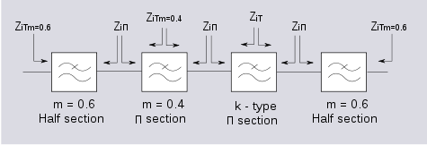
Several L half-sections may be cascaded to form a composite filter. The most important rule when constructing a composite image filter is that the image impedances must always face an identical impedance; like must always face like. T sections must always face T sections, Π sections must always face Π sections, k-type must always face k-type (or the side of an m-type which has the k-type impedance) and m-type must always face m-type. Furthermore, m-type impedances of different values of m cannot face each other. Nor can sections of any type which have different values of cut-off frequency.Sections at the beginning and end of the filter are often chosen for their impedance match in to the terminations rather than the shape of their frequency response. For this purpose, m-type sections of m = 0.6 are the most common choice. An alternative is mm'-type sections of m=0.7230 and m
The inner sections of the filter are most commonly chosen to be constant k since these produce the greatest stopband attenuation. However, one or two m-type sections might also be included to improve the rate of fall from pass to stopband. A low value of m is chosen for m-types used for this purpose. The lower the value of m, the faster the transition, while at the same time, the stopband attenuation becomes less, increasing the need to use extra k-type sections as well. An advantage of using mm'-types for impedance matching is that these type of end sections will have a fast transition anyway (much more so than m=0.6 m-type) because mm
Constant resistance sections may also be required, if the filter is being used on a transmission line, to improve the flatness of the passband response. This is necessary because the transmission line response is not usually anywhere near perfectly flat. These sections would normally be placed closest to the line since they present a predictable impedance to the line and also tend to mask the indeterminate impedance of the line from the rest of the filter. There is no issue with matching constant resistance sections to each other even when the sections are operating on totally different frequency bands. All sections can be made to have precisely the same image impedance of a fixed resistance.
Image filter types
- Constant k filterConstant k filterConstant k filters, also k-type filters, are a type of electronic filter designed using the image method. They are the original and simplest filters produced by this methodology and consist of a ladder network of identical sections of passive components...
- m-derived filterM-derived filterm-derived filters or m-type filters are a type of electronic filter designed using the image method. They were invented by Otto Zobel in the early 1920s. This filter type was originally intended for use with telephone multiplexing and was an improvement on the existing constant k type filter...
- General mn-type image filtersGeneral mn-type image filtersThese filters are electrical wave filters designed using the image method. They are an invention of Otto Zobel at AT&T Corp.. They are a generalisation of the m-type filter in that a transform is applied that modifies the transfer function while keeping the image impedance unchanged. For filters...
- mm'-type filterMm'-type filtermm'-type filters, also called double-m-derived filters, are a type of electronic filter designed using the image method. They were patented by Otto Zobel in 1932...
- Zobel networkZobel networkZobel networks are a type of filter section based on the image impedance design principle. They are named after Otto Zobel of Bell Labs who published a much referenced paper on image filters in 1923. The distinguishing feature of Zobel networks is that the input impedance is fixed in the design...
- Lattice filter
People
- Otto Zobel
- George CampbellGeorge Ashley CampbellGeorge Ashley Campbell was a pioneer in developing and applying quantitative mathematical methods to the problems of long-distance telegraphy and telephony. His most important contributions were to the theory and implementation of the use of loading coils and the first wave filters designed to...
- John Renshaw CarsonJohn Renshaw CarsonJohn Renshaw Carson , who published as J. R. Carson, was a noted transmission theorist for early communications systems...
- Oliver HeavisideOliver HeavisideOliver Heaviside was a self-taught English electrical engineer, mathematician, and physicist who adapted complex numbers to the study of electrical circuits, invented mathematical techniques to the solution of differential equations , reformulated Maxwell's field equations in terms of electric and...