Common collector
Encyclopedia
Electronics
Electronics is the branch of science, engineering and technology that deals with electrical circuits involving active electrical components such as vacuum tubes, transistors, diodes and integrated circuits, and associated passive interconnection technologies...
, a common-collector amplifier
Electronic amplifier
An electronic amplifier is a device for increasing the power of a signal.It does this by taking energy from a power supply and controlling the output to match the input signal shape but with a larger amplitude...
(also known as an emitter follower or BJT voltage follower) is one of three basic single-stage bipolar junction transistor
Bipolar junction transistor
|- align = "center"| || PNP|- align = "center"| || NPNA bipolar transistor is a three-terminal electronic device constructed of doped semiconductor material and may be used in amplifying or switching applications. Bipolar transistors are so named because their operation involves both electrons...
(BJT) amplifier topologies, typically used as a voltage buffer. In this circuit the base terminal of the transistor serves as the input, the emitter is the output, and the collector is common to both (for example, it may be tied to ground reference
Ground (electricity)
In electrical engineering, ground or earth may be the reference point in an electrical circuit from which other voltages are measured, or a common return path for electric current, or a direct physical connection to the Earth....
or a power supply rail), hence its name. The analogous field-effect transistor
Field-effect transistor
The field-effect transistor is a transistor that relies on an electric field to control the shape and hence the conductivity of a channel of one type of charge carrier in a semiconductor material. FETs are sometimes called unipolar transistors to contrast their single-carrier-type operation with...
circuit is the common-drain amplifier
Common drain
In electronics, a common-drain amplifier, also known as a source follower, is one of three basic single-stage field effect transistor amplifier topologies, typically used as a voltage buffer. In this circuit the gate terminal of the transistor serves as the input, the source is the output, and the...
.
Basic circuit
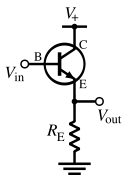
The circuit can be explained by viewing the transistor as being under the control of negative feedback. From this viewpoint, a common-collector stage (Fig. 1) is an amplifier with full series negative feedback. In this configuration (Fig. 2 with β = 1), the entire output voltage VOUT is placed contrary and in series with the input voltage VIN. Thus the two voltages are subtracted according to KVL (the subtractor from the function block diagram is implemented just by the input loop) and their difference Vdiff = VIN - VOUT is applied to the base-emitter junction. The transistor monitors continuously Vdiff and adjusts its emitter voltage almost equal (less VBEO) to the input voltage by passing the according collector current through the emitter resistor RE. As a result, the output voltage follows the input voltage variations from VBEO up to V+; hence the name, emitter follower. Intuitively, this behavior can be also understood by realizing that the base-emitter voltage in the bipolar transistor is very insensitive to bias changes, so any change in base voltage is transmitted (to good approximation) directly to the emitter. It depends slightly on various disturbances (transistor tolerances, temperature variations, load resistance, collector resistor if it is added, etc.) since the transistor reacts to these disturbances and restores the equilibrium. It never saturates even if the input voltage reaches the positive rail.The common collector circuit can be shown mathematically to have a voltage
Voltage
Voltage, otherwise known as electrical potential difference or electric tension is the difference in electric potential between two points — or the difference in electric potential energy per unit charge between two points...
gain
Gain
In electronics, gain is a measure of the ability of a circuit to increase the power or amplitude of a signal from the input to the output. It is usually defined as the mean ratio of the signal output of a system to the signal input of the same system. It may also be defined on a logarithmic scale,...
of almost unity:
-

A small voltage change on the input terminal will be replicated at the output (depending slightly on the transistor's gain and the value of the load resistance; see gain formula below). This circuit is useful because it has a large input impedance Input impedanceThe input impedance of an electrical network is the equivalent impedance "seen" by a power source connected to that network. If the source provides known voltage and current, such impedance can be calculated using Ohm's Law...
, so it will not load down the previous circuit:-

and a small output impedanceOutput impedanceThe output impedance, source impedance, or internal impedance of an electronic device is the opposition exhibited by its output terminals to an alternating current of a particular frequency as a result of resistance, inductance and capacitance...
, so it can drive low-resistance loads:-

Typically, the emitter resistor is significantly larger and can be removed from the equation:-

Applications
The low output impedance allows a source with a large output impedance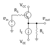 Output impedanceThe output impedance, source impedance, or internal impedance of an electronic device is the opposition exhibited by its output terminals to an alternating current of a particular frequency as a result of resistance, inductance and capacitance...
to drive a small load impedance; it functions as a voltage bufferBuffer amplifierA buffer amplifier is one that provides electrical impedance transformation from one circuit to another...
. In other words, the circuit has current gain (which depends largely on the hFE of the transistor) instead of voltage gain. A small change to the input current results in much larger change in the output current supplied to the output load.
One aspect of buffer action is transformation of impedances. For example, the Thévenin resistanceThévenin's theoremIn circuit theory, Thévenin's theorem for linear electrical networks states that any combination of voltage sources, current sources, and resistors with two terminals is electrically equivalent to a single voltage source V and a single series resistor R. For single frequency AC systems the theorem...
of a combination of a voltage follower driven by a voltage source with high Thevenin resistance is reduced to only the output resistance of the voltage follower, a small resistance. That resistance reduction makes the combination a more ideal voltage source. Conversely, a voltage follower inserted between a small load resistance and a driving stage presents a large load to the driving stage, an advantage in coupling a voltage signal to a small load.
This configuration is commonly used in the output stages of class-B and class-AB amplifier — the base circuit is modified to operate the transistor in class-B or AB mode. In class-A mode, sometimes an active current sourceCurrent sourceA current source is an electrical or electronic device that delivers or absorbs electric current. A current source is the dual of a voltage source. The term constant-current sink is sometimes used for sources fed from a negative voltage supply...
is used instead of RE (Fig. 4) to improve linearity and/or efficiency.
Characteristics
At low frequencies and using a simplified hybrid-pi modelHybrid-pi modelThe hybrid-pi model is a popular circuit model used for analyzing the small signal behavior of bipolar junction and field effect transistors. The model can be quite accurate for low-frequency circuits and can easily be adapted for higher frequency circuits with the addition of appropriate...
, the following small-signal characteristics can be derived. (Parameter and the parallelParallel (geometry)Parallelism is a term in geometry and in everyday life that refers to a property in Euclidean space of two or more lines or planes, or a combination of these. The assumed existence and properties of parallel lines are the basis of Euclid's parallel postulate. Two lines in a plane that do not...
lines indicate components in parallel.)
Definition Expression Approximate expression Conditions Current gain GainIn electronics, gain is a measure of the ability of a circuit to increase the power or amplitude of a signal from the input to the output. It is usually defined as the mean ratio of the signal output of a system to the signal input of the same system. It may also be defined on a logarithmic scale,...


Voltage gain GainIn electronics, gain is a measure of the ability of a circuit to increase the power or amplitude of a signal from the input to the output. It is usually defined as the mean ratio of the signal output of a system to the signal input of the same system. It may also be defined on a logarithmic scale,...


Input resistance 

Output resistance 

Where is the ThéveninThévenin's theoremIn circuit theory, Thévenin's theorem for linear electrical networks states that any combination of voltage sources, current sources, and resistors with two terminals is electrically equivalent to a single voltage source V and a single series resistor R. For single frequency AC systems the theorem...
equivalent source resistance.
Derivations
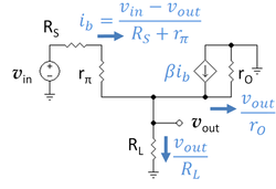 Figure 5 shows a low-frequency hybrid-pi model for the circuit of Figure 3. Using Ohm's law
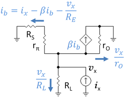 Ohm's lawOhm's law states that the current through a conductor between two points is directly proportional to the potential difference across the two points...
various currents have been determined and these results are shown on the diagram. Applying Kirchhoff's current law at the emitter one finds:
Define the following resistance values:

Then collecting terms the voltage gain is found as:
From this result the gain approaches unity (as expected for a buffer amplifierBuffer amplifierA buffer amplifier is one that provides electrical impedance transformation from one circuit to another...
) if the resistance ratio in the denominator is small. This ratio decreases with larger values of current gain β and with larger vales of RE.
The input resistance is found as:
The transistor output resistance rO ordinarily is large compared to the load RL and therefore RL dominates RE. From this result, the input resistance of the amplifier is much larger than the output load resistance RL for large current gain β. That is, placing the amplifier between the load and the source presents a smaller (high-resistive) load to the source than direct coupling to RL, which results in less signal attenuation in the source impedance RS as a consequence of voltage division.
Figure 6 shows the small-signal circuit of Figure 5 with the input short-circuited and a test current placed at its output. The output resistance is found using this circuit as:
Using Ohm's law, various currents have been found, as indicated on the diagram. Collecting the terms for the base current, the base current is found as:
where RE is defined above. Using this value for base current, Ohm's law provides vx as:
Substituting for the base current, and collecting terms,
where || denotes a parallel connection and R is defined above. Because R generally is a small resistance when the current gain β is large, R dominates the output impedance which therefore also is small. A small output impedance means the series combination of the original voltage source and the voltage follower presents a Thévenin voltage sourceThévenin's theoremIn circuit theory, Thévenin's theorem for linear electrical networks states that any combination of voltage sources, current sources, and resistors with two terminals is electrically equivalent to a single voltage source V and a single series resistor R. For single frequency AC systems the theorem...
with a lower Thévenin resistance at its output node; that is, the combination of voltage source with voltage follower makes a more ideal voltage source than the original one.
See also
- Negative feedback amplifier
- Buffer amplifierBuffer amplifierA buffer amplifier is one that provides electrical impedance transformation from one circuit to another...
- Common drainCommon drainIn electronics, a common-drain amplifier, also known as a source follower, is one of three basic single-stage field effect transistor amplifier topologies, typically used as a voltage buffer. In this circuit the gate terminal of the transistor serves as the input, the source is the output, and the...
- Two-port networkTwo-port networkA two-port network is an electrical circuit or device with two pairs of terminals connected together internally by an electrical network...
s - Hybrid-pi modelHybrid-pi modelThe hybrid-pi model is a popular circuit model used for analyzing the small signal behavior of bipolar junction and field effect transistors. The model can be quite accurate for low-frequency circuits and can easily be adapted for higher frequency circuits with the addition of appropriate...
- Common emitterCommon emitterIn electronics, a common-emitter amplifier is one of three basic single-stage bipolar-junction-transistor amplifier topologies, typically used as a voltage amplifier...
- Common baseCommon baseIn electronics, a common-base amplifier is one of three basic single-stage bipolar junction transistor amplifier topologies, typically used as a current buffer or voltage amplifier...
- Common sourceCommon sourceIn electronics, a common-source amplifier is one of three basic single-stage field-effect transistor amplifier topologies, typically used as a voltage or transconductance amplifier. The easiest way to tell if a FET is common source, common drain, or common gate is to examine where the signal...
- Common gateCommon gateIn electronics, a common-gate amplifier is one of three basic single-stage field-effect transistor amplifier topologies, typically used as a current buffer or voltage amplifier...
- Emitter degeneration
External links
- Learning Common Collector Configuration
- R Victor Jones: Basic BJT Amplifier Configurations
- NPN Common Collector Amplifier — HyperPhysicsHyperPhysicsHyperPhysics is an educational resource about physics topics. The information architecture of the website is based on trees that organize topics from general to specific...
- Theodore Pavlic: ECE 327: Transistor Basics; part 6: npn Emitter Follower
- Doug Gingrich: The common collector amplifier U of Alberta
- Raymond Frey: Lab exercises U of Oregon
-
-
-
-