


of a signal.
It does this by taking energy from a power supply
and controlling the output to match the input signal shape but with a larger amplitude
. In this sense, an amplifier may be considered as modulating the output of the power supply.
The term amplifier is applied to anything from a circuit (or stage) using a single active device to a complete system such as a packaged audio hi-fi amplifier.
Types of amplifier
Amplifiers can be specified according to their input and output properties. They have some kind of gain, or multiplication factor relating the magnitude of the output signal to the input signal. The gain may be specified as the ratio of output voltage to input voltage (voltage gain), output power to input power (power gain
), or some combination of current, voltage and power. In many cases, with input and output in the same units, gain will be unitless (although often expressed in decibels); for others this is not necessarily so. For example, a transconductance amplifier has a gain with units of conductance (output current per input voltage). The power gain of an amplifier depends on the source and load impedances used as well as its voltage gain; while an RF
amplifier may have its impedances optimized for power transfer, audio and instrumentation amplifiers are normally employed with amplifier input and output impedances optimized for least loading and highest quality. So an amplifier that is said to have a gain of 20 dB might have a voltage gain of ten times and an available power gain of much more than 20 dB (100 times power ratio), yet be delivering a much lower power gain if, for example, the input is a 600 ohm microphone and the output is a 47 kilohm power amplifier's input socket.
In most cases an amplifier should be linear; that is, the gain should be constant for any combination of input and output signal. If the gain is not constant, e.g., by clipping the output signal at the limits of its capabilities, the output signal will be distorted. There are however cases where variable gain
is useful.
There are many types of electronic amplifiers, commonly used in radio
and television
transmitter
s and receivers
, high-fidelity ("hi-fi") stereo equipment, microcomputers and other electronic digital equipment, and guitar
and other instrument amplifier
s. Critical components include active devices, such as vacuum tube
s or transistor
s. A brief introduction to the many types of electronic amplifier follows.
Power amplifier
The term power amplifier is a relative term with respect to the amount of power delivered to the load and/or sourced by the supply circuit. In general a power amplifier is designated as the last amplifier in a transmission chain (the output stage) and is the amplifier stage that typically requires most attention to power efficiency. Efficiency considerations lead to various classes of power amplifier based on the biasing of the output transistors or tubes: see power amplifier classes.Power amplifiers by application
- Audio amplifier#PowerAudio power amplifiers
- RF power amplifierRf power amplifierAn RF power amplifier is a type of electronic amplifier used to convert a low-power radio-frequency signal into a larger signal of significant power, typically for driving the antenna of a transmitter...
, such as for transmitter final stages (see also: Linear amplifierLinear amplifierA linear amplifier is an electronic circuit whose output is proportional to its input, but capable of delivering more power into a load. The term usually refers to a type of radio-frequency power amplifier, some of which have output power measured in kilowatts, and are used in amateur radio...
). - Servo motor controllersServo driveA servo drive is a special electronic amplifier used to power electric servomechanisms.A servo drive monitors the feedback signal from the servomechanism and continually adjusts for deviation from expected behavior.-Function:...
, where linearity is not important.
Power amplifier circuits
Can be divided into:- Vacuum tubeVacuum tubeIn electronics, a vacuum tube, electron tube , or thermionic valve , reduced to simply "tube" or "valve" in everyday parlance, is a device that relies on the flow of electric current through a vacuum...
/Valve, Hybrid or Transistor power amplifiers - Push-pull outputPush-pull outputA push–pull output is a type of electronic circuit that can drive either a positive or a negative current into a load. Push–pull outputs are present in TTL and CMOS digital logic circuits and in some types of amplifiers, and are usually realized as a complementary pair of transistors, one...
or Single-ended output stages
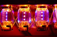
Vacuum-tube (valve) amplifiers
According to Symons, while semiconductor amplifiers have largely displaced valve amplifiers for low power applications, valve amplifiers are much more cost effective in high power applications such as "radar, countermeasures equipment, or communications equipment" (p. 56). Many microwave amplifiers are specially designed valves, such as the klystron
, gyrotron
, traveling wave tube
, and crossed-field amplifier
, and these microwave valves provide much greater single-device power output at microwave frequencies than solid-state devices (p. 59).
Valves/tube amplifiers also have niche uses in other areas, such as
- electric guitarElectric guitarAn electric guitar is a guitar that uses the principle of direct electromagnetic induction to convert vibrations of its metal strings into electric audio signals. The signal generated by an electric guitar is too weak to drive a loudspeaker, so it is amplified before sending it to a loudspeaker...
amplification - in Russian military aircraft, for their EMPElectromagnetic pulseAn electromagnetic pulse is a burst of electromagnetic radiation. The abrupt pulse of electromagnetic radiation usually results from certain types of high energy explosions, especially a nuclear explosion, or from a suddenly fluctuating magnetic field...
tolerance - niche audio for their sound qualities (recording, and audiophileAudiophileAn audiophile is a person who enjoys listening to recorded music, usually in a home. Some audiophiles are more interested in collecting and listening to music, while others are more interested in collecting and listening to audio components, whose "sound quality" they consider as important as the...
equipment)
Transistor amplifiers
The essential role of this active element is to magnify an input signal to yield a significantly larger output signal. The amount of magnification (the "forward gain") is determined by the external circuit design as well as the active device.Many common active devices in transistor amplifiers are bipolar junction transistor
s (BJTs) and metal oxide semiconductor field-effect transistors (MOSFET
s).
Applications are numerous, some common examples are audio amplifiers in a home stereo or PA system
, RF high power generation for semiconductor equipment, to RF and Microwave applications such as radio transmitters.
Transistor-based amplifier can be realized using various configurations: for example with a bipolar junction transistor we can realize common base
, common collector
or common emitter
amplifier; using a MOSFET we can realize common gate
, common source
or common drain
amplifier. Each configuration has different characteristic (gain, impedance...).
Operational amplifiers (op-amps)
An operational amplifier is an amplifier circuit with very high open loop gain and differential inputs which employs external feedback for control of its transfer function or gain. Although the term is today commonly applied to integrated circuits, the original operational amplifier design was implemented with valves.
Fully differential amplifiers
A fully differential amplifier is a solid state integrated circuit amplifier which employs external feedback for control of its transfer function or gain. It is similar to the operational amplifier but it also has differential output pins.
it is formed from bjt.
Video amplifiers
These deal with video signals and have varying bandwidths depending on whether the video signal is for SDTV, EDTV, HDTV 720p or 1080i/p etc.. The specification of the bandwidth itself depends on what kind of filter is used and which point ( or for example) the bandwidth is measured. Certain requirements for step response and overshoot are necessary in order for acceptable TV images to be presented.Oscilloscope vertical amplifiers
These are used to deal with video signals to drive an oscilloscope display tube and can have bandwidths of about . The specifications on step response, rise time, overshoot and aberrations can make the design of these amplifiers extremely difficult. One of the pioneers in high bandwidth vertical amplifiers was the Tektronixcompany.
Distributed amplifiers
These use transmission lines to temporally split the signal and amplify each portion separately in order to achieve higher bandwidth than can be obtained from a single amplifying device. The outputs of each stage are combined in the output transmission line. This type of amplifier was commonly used on oscilloscope
s as the final vertical amplifier. The transmission lines were often housed inside the display tube glass envelope.
Switched mode amplifiers
These nonlinear amplifiers have much higher efficiencies than linear amps, and are used where the power saving justifies the extra complexity.Negative resistance devices
Negative resistances can be used as amplifiers, such as the tunnel diode
amplifier.
Travelling wave tube amplifiers
Traveling wave tubeamplifiers (TWTAs) are used for high power amplification at low microwave frequencies. They typically can amplify across a broad spectrum of frequencies; however, they are usually not as tunable as klystrons.
Klystrons
Klystrons are vacuum-devices that do not have as wide a bandwidth as TWTAs. They generally are also much heavier than TWTAs, and are therefore ill-suited for light-weight mobile applications. Klystrons are tunable, offering selective output within their specified frequency range.Musical instrument (audio) amplifiers
An audio amplifier is usually used to amplify signals such as music or speech. Several factors are especially important in the selection of musical instrument amplifiers (such as guitar amplifiers) and other audio amplifiers (although the whole of the sound systemcomponents such as microphones to loudspeakers will impact on these parameters):
- Frequency response not just the frequency range but the requirement that the signal level varies so little across the audible frequency range that the human ear notices no variation. A typical specification for audio amplifiers may be 20 HzHZHz is the International Standard symbol for Hertz, the unit of frequencyHZ may also stand for:* Habitable zone, the distance from a star where a planet can maintain Earth-like life* Hamilton Zoo, in New Zealand...
to 20 kHz +/- 0.5dB. - Power outputPower ratingIn electrical and electronic engineering, the power rating of a device is a guideline set by the manufacturer as a maximum power to be used with that device. This limit is usually set somewhat lower than the level where the device will be damaged, to allow a margin of safety.The power rating can...
the power level obtainable with little distortion, to obtain a sufficiently loud sound pressure level from the loudspeakers. - Low distortionDistortionA distortion is the alteration of the original shape of an object, image, sound, waveform or other form of information or representation. Distortion is usually unwanted, and often many methods are employed to minimize it in practice...
all amplifiers and transducers will distort to some extent; they cannot be perfectly linear, but aim to pass signals without affecting the harmonicHarmonicA harmonic of a wave is a component frequency of the signal that is an integer multiple of the fundamental frequency, i.e. if the fundamental frequency is f, the harmonics have frequencies 2f, 3f, 4f, . . . etc. The harmonics have the property that they are all periodic at the fundamental...
content of the sound more than the human ear will tolerate. That tolerance of distortion, and indeed the possibility that some "warmth" or second harmonic distortion (Tube soundTube soundTube sound is the characteristic sound associated with a vacuum tube-based audio amplifier. The audible significance of tube amplification on audio signals is a subject of continuing debate among audio enthusiasts....
) improves the "musicality" of the sound, are subjects of great debate.
Classification of amplifier stages and systems
There are many alternative classifications that address different aspects of amplifier designs, and they all express some particular perspective relating the design parameters to the objectives of the circuit. Amplifier design is always a compromise of numerous factors, such as cost, power consumption, real-world device imperfections, and a multitude of performance specifications. Below are several different approaches to classification:Input and output variables
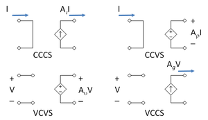
| Input | Output | Dependent source | Amplifier type |
|---|---|---|---|
| I | I | current controlled current source CCCS | current amplifier |
| I | V | current controlled voltage source CCVS | transresistance amplifier |
| V | I | voltage controlled current source VCCS | transconductance Transconductance Transconductance, also known as mutual conductance, is a property of certain electronic components. Conductance is the reciprocal of resistance; transconductance, meanwhile, is the ratio of the current change at the output port to the voltage change at the input port. It is written as gm... amplifier |
| V | V | voltage controlled voltage source VCVS | voltage amplifier |
Each type of amplifier in its ideal form has an ideal input and output resistance that is the same as that of the corresponding dependent source:
| Amplifier type | Dependent source | Input impedance | Output impedance |
|---|---|---|---|
| Current | CCCS | 0 | ∞ |
| Transresistance | CCVS | 0 | 0 |
| Transconductance | VCCS | ∞ | ∞ |
| Voltage | VCVS | ∞ | 0 |
In practice the ideal impedances are only approximated. For any particular circuit, a small-signal analysis is often used to find the impedance actually achieved. A small-signal AC test current Ix is applied to the input or output node, all external sources are set to AC zero, and the corresponding alternating voltage Vx across the test current source determines the impedance seen at that node as R = Vx / Ix.
Amplifiers designed to attach to a transmission line
at input and/or output, especially RF amplifiers
, do not fit into this classification approach. Rather than dealing with voltage or current individually, they ideally couple with an input and/or output impedance matched to the transmission line impedance, that is, match ratios of voltage to current. Many real RF amplifiers come close to this ideal. Although, for a given appropriate source and load impedance, RF amplifiers can be characterized as amplifying voltage or current, they fundamentally are amplifying power.
Common terminal
One set of classifications for amplifiers is based on which device terminal is common to both the input and the output circuit. In the case of bipolar junction transistors, the three classes are common emitter
, common base
, and common collector
. For field-effect transistor
s, the corresponding configurations are common source
, common gate
, and common drain
; for triode vacuum devices
, common cathode, common grid, and common plate. The output voltage of a common plate amplifier is the same as the input (this arrangement is used as the input presents a high impedance and does not load the signal source, although it does not amplify the voltage), i.e., the output at the cathode follows the input at the grid; consequently it was commonly called a cathode follower. By analogy the terms emitter follower and source follower are sometimes used.
Unilateral or bilateral
When an amplifier has an output that exhibits no feedback to its input side, it is called 'unilateral'. The input impedance of a unilateral amplifier is independent of the load, and the output impedance is independent of the signal source impedance.If feedback connects part of the output back to the input of the amplifier it is called a 'bilateral' amplifier. The input impedance of a bilateral amplifier is dependent upon the load, and the output impedance is dependent upon the signal source impedance.
All amplifiers are bilateral to some degree; however they may often be modeled as unilateral under operating conditions where feedback is small enough to neglect for most purposes, simplifying analysis (see the common base
article for an example).
Negative feedback
is often applied deliberately to tailor amplifier behavior. Some feedback, which may be positive or negative, is unavoidable and often undesirable, introduced, for example, by parasitic elements
such as the inherent capacitance between input and output of a device such as a transistor and capacitative coupling due to external wiring. Excessive frequency-dependent positive feedback may cause what is supposed to be an amplifier to become an oscillator.
Linear unilateral and bilateral amplifiers can be represented as two-port network
s.
Inverting or non-inverting
Another way to classify amps is the phase relationship of the input signal to the output signal. An 'inverting' amplifier produces an output 180 degrees out of phase with the input signal (that is, a polarity inversion or mirror image of the input as seen on an oscilloscope). A 'non-inverting' amplifier maintains the phase of the input signal waveforms. An emitter follower is a type of non-inverting amplifier, indicating that the signal at the emitter of a transistor is following (that is, matching with unity gain but perhaps an offset) the input signal.
This description can apply to a single stage of an amplifier, or to a complete amplifier system.
Function
Other amplifiers may be classified by their function or output characteristics. These functional descriptions usually apply to complete amplifier systems or sub-systems and rarely to individual stages.- A servo amplifierServo driveA servo drive is a special electronic amplifier used to power electric servomechanisms.A servo drive monitors the feedback signal from the servomechanism and continually adjusts for deviation from expected behavior.-Function:...
indicates an integrated feedback loop to actively control the output at some desired level. A DC servoServomechanismthumb|right|200px|Industrial servomotorThe grey/green cylinder is the [[Brush |brush-type]] [[DC motor]]. The black section at the bottom contains the [[Epicyclic gearing|planetary]] [[Reduction drive|reduction gear]], and the black object on top of the motor is the optical [[rotary encoder]] for...
indicates use at frequencies down to DC levels, where the rapid fluctuations of an audio or RF signal do not occur. These are often used in mechanical actuators, or devices such as DC motorDC motorA DC motor is an electric motor that runs on direct current electricity.-Brush:The brushed DC electric motor generates torque directly from DC power supplied to the motor by using internal commutation, stationary magnets , and rotating electrical magnets.Like all electric motors or generators,...
s that must maintain a constant speed or torqueTorqueTorque, moment or moment of force , is the tendency of a force to rotate an object about an axis, fulcrum, or pivot. Just as a force is a push or a pull, a torque can be thought of as a twist....
. An AC servo amp can do this for some ac motors. - A linear amplifier responds to different frequency components independently, and does not generate harmonic distortion or IntermodulationIntermodulationIntermodulation or intermodulation distortion is the amplitude modulation of signals containing two or more different frequencies in a system with nonlinearities...
distortion. A nonlinear amplifier does generate distortion (e.g. the output is a current to a lamp that must be either fully on or off, but the input is continuously variable; or the amplifier is used in an analog computerAnalog computerAn analog computer is a form of computer that uses the continuously-changeable aspects of physical phenomena such as electrical, mechanical, or hydraulic quantities to model the problem being solved...
where a special transfer function, such as logarithmic, is desired; or a following tuned circuit will remove the harmonics generated by a nonlinear RF amplifier). Even the most linear amplifier will have some nonlinearities, since the amplifying devices transistorTransistorA transistor is a semiconductor device used to amplify and switch electronic signals and power. It is composed of a semiconductor material with at least three terminals for connection to an external circuit. A voltage or current applied to one pair of the transistor's terminals changes the current...
s and vacuum tubes follow nonlinear power laws such as square-laws and rely on circuitry techniques to reduce their effects. - A wideband amplifier has a precise amplification factor over a wide range of frequencies, and is often used to boost signals for relay in communications systems. A narrowband amp is made to amplify only a specific narrow range of frequencies, to the exclusion of other frequencies.
- An RF amplifier refers to an amplifier designed for use in the radio frequencyRadio frequencyRadio frequency is a rate of oscillation in the range of about 3 kHz to 300 GHz, which corresponds to the frequency of radio waves, and the alternating currents which carry radio signals...
range of the electromagnetic spectrumElectromagnetic spectrumThe electromagnetic spectrum is the range of all possible frequencies of electromagnetic radiation. The "electromagnetic spectrum" of an object is the characteristic distribution of electromagnetic radiation emitted or absorbed by that particular object....
, and is often used to increase the sensitivity of a receiverReceiver (radio)A radio receiver converts signals from a radio antenna to a usable form. It uses electronic filters to separate a wanted radio frequency signal from all other signals, the electronic amplifier increases the level suitable for further processing, and finally recovers the desired information through...
or the output power of a transmitterTransmitterIn electronics and telecommunications a transmitter or radio transmitter is an electronic device which, with the aid of an antenna, produces radio waves. The transmitter itself generates a radio frequency alternating current, which is applied to the antenna. When excited by this alternating...
. - An audio amplifierAudio amplifierAn audio amplifier is an electronic amplifier that amplifies low-power audio signals to a level suitable for driving loudspeakers and is the final stage in a typical audio playback chain.The preceding stages in such a chain are low power audio amplifiers which perform tasks like pre-amplification,...
is designed for use in reproducing audio frequencies. This category subdivides into small signal amplification, and power amps which are optimised for driving speakerLoudspeakerA loudspeaker is an electroacoustic transducer that produces sound in response to an electrical audio signal input. Non-electrical loudspeakers were developed as accessories to telephone systems, but electronic amplification by vacuum tube made loudspeakers more generally useful...
s, sometimes with multiple amps grouped together as separate or bridgeable channels to accommodate different audio reproduction requirements. Frequently used terms within audio amplifiers include:- preamplifierPreamplifierA preamplifier is an electronic amplifier that prepares a small electrical signal for further amplification or processing. A preamplifier is often placed close to the sensor to reduce the effects of noise and interference. It is used to boost the signal strength to drive the cable to the main...
(preamp), that may include phonoPhonographThe phonograph record player, or gramophone is a device introduced in 1877 that has had continued common use for reproducing sound recordings, although when first developed, the phonograph was used to both record and reproduce sounds...
preamp with RIAA equalizationRIAA equalizationRIAA equalization is a specification for the correct recording of gramophone records, established by the Recording Industry Association of America...
, or tape headTape headA tape head is a type of transducer used in tape recorders to convert electrical signals to magnetic fluctuations and vice versa.-Principles of operation:...
preamps with CCIR equalisation filters; they may include filterFilter (signal processing)In signal processing, a filter is a device or process that removes from a signal some unwanted component or feature. Filtering is a class of signal processing, the defining feature of filters being the complete or partial suppression of some aspect of the signal...
s or tone control circuitry. - power amplifier (normally assumed to drive loudspeakers), headphone amplifiers, and public address amplifiers.
- stereoSTEREOSTEREO is a solar observation mission. Two nearly identical spacecraft were launched into orbits that cause them to respectively pull farther ahead of and fall gradually behind the Earth...
amplifiers imply two channels of output (left and right), although the term simply means "solid" sound (referring to three-dimensional) so quadraphonicQuadraphonicQuadraphonic sound – the most widely used early term for what is now called 4.0 surround sound – uses four channels in which speakers are positioned at the four corners of the listening space, reproducing signals that are independent of one another...
stereo was used for amplifiers with 4 channels; 5.1 and 7.1 systems refer to Home theatre systems with 5 or 7 normal spacial channels, plus a subwooferSubwooferA subwoofer is a woofer, or a complete loudspeaker, which is dedicated to the reproduction of low-pitched audio frequencies known as the "bass". The typical frequency range for a subwoofer is about 20–200 Hz for consumer products, below 100 Hz for professional live sound, and below...
channel (that is not very directional).
- preamplifier
- Buffer amplifiers, that may include emitter followers, provide a high impedanceElectrical impedanceElectrical impedance, or simply impedance, is the measure of the opposition that an electrical circuit presents to the passage of a current when a voltage is applied. In quantitative terms, it is the complex ratio of the voltage to the current in an alternating current circuit...
input for a device (perhaps another amplifier, or perhaps an energy-hungry load such as lights) that would otherwise draw too much current from the source. Line driverLine driverIn electronics, a line driver is an amplifier used to improve the strength of an analog or digital signal at its source by driving the input to the transmission line with a higher than normal signal level. This increases the quality of a transmission over a long run of cable...
s are a type of buffer intended to feed long or interference-prone interconnect cables, possibly with differentialDifferential signalingDifferential signaling is a method of transmitting information electrically by means of two complementary signals sent on two separate wires. The technique can be used for both analog signaling, as in some audio systems, and digital signaling, as in RS-422, RS-485, Ethernet , PCI Express and USB...
outputs if driving twisted pairTwisted pairTwisted pair cabling is a type of wiring in which two conductors are twisted together for the purposes of canceling out electromagnetic interference from external sources; for instance, electromagnetic radiation from unshielded twisted pair cables, and crosstalk between neighboring pairs...
s of cables. - A special type of amplifier is widely used in instruments and for signal processing, among many other varied uses. These are known as operational amplifiers or op-amps. This is because this type of amplifier is used in circuits that perform mathematical algorithmic functions, or "operations" on input signals to obtain specific types of output signals. A typical modern op-amp has differential inputs (one "inverting", one "non-inverting") and one output. An idealised op-amp has the following characteristics:
- Infinite input impedance (so as to not load circuitry it is sampling as a control input)
- Zero output impedance
- Infinite gain
- Zero propagation delay
- The performance of an op-amp with these characteristics would be entirely defined by the (usually passive) components forming a negative feedback loop around it, that is, the amplifier itself has no effect on the output.
- Today, op-amps are usually provided as integrated circuits, rather than constructed from discrete components. All real-world op-amps fall short of the idealised specification above but some modern components have remarkable performance and come close in some respects.
Interstage coupling method
Amplifiers are sometimes classified by the coupling method of the signal at the input, output, or between stages. Different types of these include:Resistive-capacitive (RC) coupled amplifier, using a network of resistors and capacitors :By design these amplifiers cannot amplify DC signals as the capacitors block the DC component of the input signal. RC-coupled amplifiers were used very often in circuits with vacuum tubes or discrete transistors. In the days of the integrated circuit a few more transistors on a chip are much cheaper and smaller than a capacitor.
Inductive-capacitive (LC) coupled amplifier, using a network of inductors and capacitors :This kind of amplifier is most often used in selective radio-frequency circuits.
Transformer
coupled amplifier, using a transformer to match impedances or to decouple parts of the circuits :Quite often LC-coupled and transformer-coupled amplifiers cannot be distinguished as a transformer is some kind of inductor.
Direct coupled amplifier, using no impedance and bias matching components :This class of amplifier was very uncommon in the vacuum tube days when the anode (output) voltage was at greater than several hundred volts and the grid (input) voltage at a few volts minus. So they were only used if the gain was specified down to DC (e.g., in an oscilloscope). In the context of modern electronics developers are encouraged to use directly coupled amplifiers whenever possible.
Frequency range
Depending on the frequency range and other properties amplifiers are designed according to different principles.- Frequency ranges down to DC are only used when this property is needed. DC amplification leads to specific complications that are avoided if possible; DC-blocking capacitorCapacitorA capacitor is a passive two-terminal electrical component used to store energy in an electric field. The forms of practical capacitors vary widely, but all contain at least two electrical conductors separated by a dielectric ; for example, one common construction consists of metal foils separated...
s are added to remove DC and sub-sonic frequencies from audio amplifiers. - Depending on the frequency range specified different design principles must be used. Up to the MHz range only "discrete" properties need be considered; e.g., a terminal has an input impedance.
- As soon as any connection within the circuit gets longer than perhaps 1% of the wavelength of the highest specified frequency (e.g., at 100 MHz the wavelength is 3 m, so the critical connection length is approx. 3 cm) design properties radically change. For example, a specified length and width of a PCBPrinted circuit boardA printed circuit board, or PCB, is used to mechanically support and electrically connect electronic components using conductive pathways, tracks or signal traces etched from copper sheets laminated onto a non-conductive substrate. It is also referred to as printed wiring board or etched wiring...
trace can be used as a selective or impedance-matching entity. - Above a few 100 MHz, it gets difficult to use discrete elements, especially inductors. In most cases PCB traces of very closely defined shapes are used instead.
The frequency range handled by an amplifier might be specified in terms of bandwidth (normally implying a response that is 3 dB
down when the frequency reaches the specified bandwidth), or by specifying a frequency response that is within a certain number of decibel
s between a lower and an upper frequency (e.g. "20 Hz to 20 kHz plus or minus 1 dB").
Type of load
- Untuned
- audio
- video
- Tuned (RF amps) used for amplifying a single radio frequencyRadio frequencyRadio frequency is a rate of oscillation in the range of about 3 kHz to 300 GHz, which corresponds to the frequency of radio waves, and the alternating currents which carry radio signals...
or a band of frequencies
Implementation
Amplifiers are implemented using active elements of different kinds:- The first active elements were relays. They were for example used in transcontinental telegraph lines: a weak current was used to switch the voltage of a battery to the outgoing line.
- For transmitting audio, carbon microphones were used as the active element. This was used to modulate a radio-frequency source in one of the first AM audio transmissions, by Reginald FessendenReginald FessendenReginald Aubrey Fessenden , a naturalized American citizen born in Canada, was an inventor who performed pioneering experiments in radio, including early—and possibly the first—radio transmissions of voice and music...
on Dec. 24, 1906. - In the 1960s, the transistor started to take over. These days, discrete transistors are still used in high-power amplifiers and in specialist audio devices.
- Up to the early 1970s, most amplifiers used vacuum tubes. Today, tubes are used for specialist audio applications such as guitar amplifiers and audiophile amplifiers. Many broadcast transmitters still use vacuum tubes.
- Beginning in the 1970s, more and more transistors were connected on a single chip therefore creating the integrated circuitIntegrated circuitAn integrated circuit or monolithic integrated circuit is an electronic circuit manufactured by the patterned diffusion of trace elements into the surface of a thin substrate of semiconductor material...
. A large number of amplifiers commercially available today are based on integrated circuits.
For exotic purposes, other active elements have been used. For example, in the early days of the communication satellite parametric amplifiers were used. The core circuit was a diode whose capacity was changed by an RF signal created locally. Under certain conditions, this RF signal provided energy that was modulated by the extremely weak satellite signal received at the earth station. The operating principle of a parametric amplifier is somewhat similar to the principle by which children keep their swings in motion: as long as the swing moves you only need to change a parameter of the swinging entity; e.g., you must move your center of gravity up and down. In our case, the capacity of the diode is changed periodically.
Angle of flow or conduction angle
Power amplifier circuits (output stages) are classified as A, B, AB and C for analog designs, and class D and E for switching designs based upon the conduction angle or angle of flow, Θ, of the input signal through the (or each) output amplifying device, that is, the portion of the input signal cycle during which the amplifying device conducts. The image of the conduction angle is derived from amplifying a sinusoidal signal. (If the device is always on, Θ = 360°.) The angle of flow is closely related to the amplifier power efficiency. The various classes are introduced below, followed by more detailed discussion under individual headings later on.Class A
- 100% of the input signal is used (conduction angle Θ = 360° or 2π); i.e., the active element remains conducting (works in its "linear" range) all of the time. Where efficiency is not a consideration, most small signal linear amplifierLinear amplifierA linear amplifier is an electronic circuit whose output is proportional to its input, but capable of delivering more power into a load. The term usually refers to a type of radio-frequency power amplifier, some of which have output power measured in kilowatts, and are used in amateur radio...
s are designed as class A. Class-A amplifiers are typically more linear and less complex than other types, but are very inefficient. This type of amplifier is most commonly used in small-signal stages or for low-power applications (such as driving headphones). Subclass A2 is sometimes used to refer to vacuum-tube class-A stages where the grid is allowed to be driven slightly positive on signal peaks, resulting in slightly more power than normal class A (A1; where the grid is always negative), but incurring more distortion.
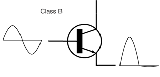
Class B
50% of the input signal is used (Θ = 180° or π; i.e., the active element works in its linear range half of the time and is more or less turned off for the other half). In most class B, there are two output devices (or sets of output devices), each of which conducts alternately (push–pull) for exactly 180° (or half cycle) of the input signal; selective RF amplifiers can also be implemented using a single active element.
These amplifiers are subject to crossover distortion if the transition from one active element to the other is not perfect, as when two complementary transistors (i.e., one PNP, one NPN) are connected as two emitter followers with their base and emitter terminals in common, requiring the base voltage to slew across the region where both devices are turned off.
Class AB
- Here the two active elements conduct more than half of the time as a means to reduce the cross-over distortions of class-B amplifiers. In the example of the complementary emitter followers a bias network allows for more or less quiescent current thus providing an operating point somewhere between class A and class B. Sometimes a figure is added (e.g., AB1 or AB2) for vacuum-tube stages where the grid voltage is always negative with respect to the cathode (class AB1) or may be slightly positive (hence drawing grid current, adding more distortion, but giving slightly higher output power) on signal peaks (class AB2). Solid-state class-AB amplifier circuits are one of the most popular amplifier topologies used today.
Class C
- Less than 50% of the input signal is used (conduction angle Θ < 180°). The advantage is potentially high efficiency, but a disadvantage is high distortion.
Class D
- These use switching to achieve a very high power efficiency (more than 90% in modern designs). By allowing each output device to be either fully on or off, losses are minimized. The analog output is created by pulse-width modulationPulse-width modulationPulse-width modulation , or pulse-duration modulation , is a commonly used technique for controlling power to inertial electrical devices, made practical by modern electronic power switches....
; i.e., the active element is switched on for shorter or longer intervals instead of modifying its resistance. There are more complicated switching schemes like sigma-delta modulationDelta-sigma modulationDelta-sigma modulation is a method for encoding high-resolution or analog signals into lower-resolution digital signals. The conversion is done using error feedback, where the difference between the two signals is measured and used to improve the conversion...
, to improve some performance aspects like lower distortions or better efficiency.
Additional classes
- There are several other amplifier classes, although they are mainly variations of the previous classes. For example, class-G and class-H amplifiers are marked by variation of the supply rails (in discrete steps or in a continuous fashion, respectively) following the input signal. Wasted heat on the output devices can be reduced as excess voltage is kept to a minimum. The amplifier that is fed with these rails itself can be of any class. These kinds of amplifiers are more complex, and are mainly used for specialized applications, such as very high-power units. Also, class-E and class-F amplifiers are commonly described in literature for radio-frequency applications where efficiency of the traditional classes is important, yet several aspects deviate substantially from their ideal values. These classes use harmonic tuning of their output networks to achieve higher efficiency and can be considered a subset of class C due to their conduction-angle characteristics.
The classes can be most easily understood using the diagrams in each section below. For the sake of illustration, a bipolar junction transistor
is shown as the amplifying device, but in practice this could be a MOSFET
or vacuum-tube device. In an analog amplifier (the most common kind), the signal is applied to the input terminal of the device (base, gate or grid), and this causes a proportional output drive current
to flow out of the output terminal. The output drive current comes from the power supply.
Class A
Amplifying devices operating in class A conduct over the whole of the input cycle. A class-A amplifier is distinguished by the output stage being biased into class A (see definition above).Advantages of class-A amplifiers
- Class-A designs are simpler than other classes; for example class-AB and -B designs require two devices (push–pull output) to handle both halves of the waveform; class A can use a single device single-endedSingle-ended signallingSingle-ended signaling is the simplest and most commonly used method of transmitting electrical signals over wires. One wire carries a varying voltage that represents the signal, while the other wire is connected to a reference voltage, usually ground....
. - The amplifying element is biased so the device is always conducting to some extent, normally implying the quiescent (small-signal) collector current (for transistorTransistorA transistor is a semiconductor device used to amplify and switch electronic signals and power. It is composed of a semiconductor material with at least three terminals for connection to an external circuit. A voltage or current applied to one pair of the transistor's terminals changes the current...
s; drain current for FETFetFet is a municipality in Akershus county, Norway. It is part of the Romerike traditional region. The administrative centre of the municipality is the village of Fetsund.Fet was established as a municipality on 1 January 1838...
s or anode/plate current for vacuum tubeVacuum tubeIn electronics, a vacuum tube, electron tube , or thermionic valve , reduced to simply "tube" or "valve" in everyday parlance, is a device that relies on the flow of electric current through a vacuum...
s) is close to the most linear portion of its transconductanceTransconductanceTransconductance, also known as mutual conductance, is a property of certain electronic components. Conductance is the reciprocal of resistance; transconductance, meanwhile, is the ratio of the current change at the output port to the voltage change at the input port. It is written as gm...
curve. - Because the device is never shut off completely there is no "turn on" time, little problem with charge storage, and generally better high frequency performance and feedback loop stability (and usually fewer high-order harmonics).
- The point at which the device comes closest to being cut off is not close to zero signal, so the problem of crossover distortionCrossover distortionCrossover distortion is a type of distortion which is caused by switching between devices driving a load, most often when the devices are matched...
associated with class-AB and -B designs is avoided.
Disadvantage of class-A amplifiers
- They are very inefficient; a theoretical maximum of 50% is obtainable with inductive output coupling and only 25% with capacitive coupling, unless deliberate use of nonlinearities is made (such as in square-law output stages). In a power amplifier this not only wastes power and limits battery operation, it may place restrictions on the output devices that can be used (for example: ruling out some audio triodes if modern low-efficiency loudspeakers are to be used), and will increase costs. Inefficiency comes not just from the fact that the device is always conducting to some extent (that happens even with class AB, yet its efficiency can be close to that of class B); it is that the standing current is roughly half the maximum output current (although this can be less with square law output stage), together with the problem that a large part of the power supply voltage is developed across the output device at low signal levels (as with classes AB and B, but unlike output stages such as class D). If high output powers are needed from a class-A circuit, the power waste (and the accompanying heat) will become significant. For every wattWattThe watt is a derived unit of power in the International System of Units , named after the Scottish engineer James Watt . The unit, defined as one joule per second, measures the rate of energy conversion.-Definition:...
delivered to the loadExternal electric loadIf an electric circuit has a well-defined output terminal, the circuit connected to this terminal is the load....
, the amplifier itself will, at best, dissipate another watt. For large powers this means very large and expensive power supplies and heat sinking.
Class-A designs have largely been superseded by the more efficient designs for power amplifiers, though they remain popular with some hobbyists, mostly for their simplicity. Also, many audiophile
s believe that class A gives the best sound quality (for their absence of crossover distortion
and reduced odd-harmonic and high-order harmonic distortion) which provides a good market for expensive high fidelity class-A amps.
Single-ended and triode class-A amplifiers
Some aficionados who prefer class-A amplifiers also prefer the use of thermionic valve (or "tube") designs instead of transistors, especially in Single-ended triodeoutput configurations for several claimed reasons:
- Single-ended output stages (be they tube or transistor) have an asymmetrical transfer functionTransfer functionA transfer function is a mathematical representation, in terms of spatial or temporal frequency, of the relation between the input and output of a linear time-invariant system. With optical imaging devices, for example, it is the Fourier transform of the point spread function i.e...
, meaning that even order harmonics in the created distortion tend not to be canceled (as they are in push–pull output stages); by using tubes OR FETFetFet is a municipality in Akershus county, Norway. It is part of the Romerike traditional region. The administrative centre of the municipality is the village of Fetsund.Fet was established as a municipality on 1 January 1838...
s most of the distortion is from the square law transfer characteristic and so second-order, which some consider to be "warmer" and more pleasant. - For those who prefer low distortion figures, the use of tubes with class A (generating little odd-harmonic distortion, as mentioned above) together with symmetrical circuits (such as push–pull output stages, or balanced low-level stages) results in the cancellation of most of the even distortion harmonics, hence the removal of most of the distortion.
- Though good amplifier design can reduce harmonic distortion patterns to almost nothing, distortion is essential to the sound of electric guitarElectric guitarAn electric guitar is a guitar that uses the principle of direct electromagnetic induction to convert vibrations of its metal strings into electric audio signals. The signal generated by an electric guitar is too weak to drive a loudspeaker, so it is amplified before sending it to a loudspeaker...
amplifiers, for example, and is held by recording engineers to offer more flattering microphones and to enhance "clinical-sounding" digital technology. - Historically, valve amplifiers often used a class-A power amplifier simply because valves are large and expensive; many class-A designs use only a single device.
Transistors are much cheaper, and so more elaborate designs that give greater efficiency but use more parts are still cost-effective. A classic application for a pair of class-A devices is the long-tailed pair, which is exceptionally linear, and forms the basis of many more complex circuits, including many audio amplifiers and almost all op-amps
.
Class-A amplifiers are often used in output stages of high quality op-amp
s (although the accuracy of the bias in low cost op-amps such as the 741 may result in class A or class AB or class B, varying from device to device or with temperature). They are sometimes used as medium-power, low-efficiency, and high-cost audio amplifiers. The power consumption is unrelated to the output power. At idle (no input), the power consumption is essentially the same as at high output volume. The result is low efficiency and high heat dissipation.
Class B and AB
Class-B or -AB push–pull circuits are the most common design type found in audio power amplifiers. Class AB is widely considered a good compromise for audio amplifiers, since much of the time the music is quiet enough that the signal stays in the "class A" region, where it is amplified with good fidelity, and by definition if passing out of this region, is large enough that the distortion products typical of class B are relatively small. The crossover distortion can be reduced further by using negative feedback. Class-B and -AB amplifiers are sometimes used for RF linear amplifiers as well. Class-B amplifiers are also favored in battery-operated devices, such as transistor radios.
Class B
in the early IBM Personal Computers with beeps, and it can be used in RF power amplifier
where the distortion levels are less important. However, class C is more commonly used for this.
A practical circuit using class-B elements is the push–pull stage
, such as the very simplified complementary pair arrangement shown below. Here, complementary or quasi-complementary devices are each used for amplifying the opposite halves of the input signal, which is then recombined at the output. This arrangement gives excellent efficiency, but can suffer from the drawback that there is a small mismatch in the cross-over region at the "joins" between the two halves of the signal, as one output device has to take over supplying power exactly as the other finishes. This is called crossover distortion
. An improvement is to bias the devices so they are not completely off when they're not in use. This approach is called class AB operation.
Class AB
In class-AB operation, each device operates the same way as in class B over half the waveform, but also conducts a small amount on the other half. As a result, the region where both devices simultaneously are nearly off (the "dead zone") is reduced. The result is that when the waveforms from the two devices are combined, the crossover is greatly minimised or eliminated altogether. The exact choice of quiescent current, the standing current through both devices when there is no signal, makes a large difference to the level of distortion (and to the risk of thermal runaway, that may damage the devices); often the bias voltage applied to set this quiescent current has to be adjusted with the temperature of the output transistors (for example in the circuit at the beginning of the article the diodes would be mounted physically close to the output transistors, and chosen to have a matched temperature coefficient). Another approach (often used as well as thermally tracking bias voltages) is to include small value resistors in series with the emitters.
Class AB sacrifices some efficiency over class B in favor of linearity, thus is less efficient (below 78.5% for full-amplitude sinewaves in transistor amplifiers, typically; much less is common in class-AB vacuum-tube amplifiers). It is typically much more efficient than class A.
Class C
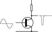
s) can tolerate the distortion. The usual application for class-C amplifiers is in RF transmitter
s operating at a single fixed carrier frequency, where the distortion is controlled by a tuned load on the amplifier. The input signal is used to switch the active device causing pulses of current to flow through a tuned circuit
forming part of the load.
The class-C amplifier has two modes of operation: tuned and untuned. The diagram shows a waveform from a simple class-C circuit without the tuned load. This is called untuned operation, and the analysis of the waveforms shows the massive distortion that appears in the signal. When the proper load (e.g., an inductive-capacitive filter plus a load resistor) is used, two things happen. The first is that the output's bias level is clamped with the average output voltage equal to the supply voltage. This is why tuned operation is sometimes called a clamper. This allows the waveform to be restored to its proper shape despite the amplifier having only a one-polarity supply. This is directly related to the second phenomenon: the waveform on the center frequency becomes less distorted. The residual distortion is dependent upon the bandwidth of the tuned load, with the center frequency seeing very little distortion, but greater attenuation the farther from the tuned frequency that the signal gets.
The tuned circuit resonates at one frequency, the fixed carrier frequency, and so the unwanted frequencies are suppressed, and the wanted full signal (sine wave) will be extracted by the tuned load. The signal bandwidth of the amplifier is limited by the Q-factor of the tuned circuit but this is not a serious limitation. Any residual harmonics can be removed using a further filter.
In practical class-C amplifiers a tuned load is invariably used. In one common arrangement the resistor shown in the circuit above is replaced with a parallel-tuned circuit consisting of an inductor and capacitor in parallel, whose components are chosen to resonate the frequency of the input signal. Power can be coupled to a load by transformer action with a secondary coil wound on the inductor. The average voltage at the drain is then equal to the supply voltage, and the signal voltage appearing across the tuned circuit varies from near zero to near twice the supply voltage during the rf cycle. The input circuit is biassed so that the active element (e.g. transistor) conducts for only a fraction of the rf cycle, usually one third (120 degrees) or less.
The active element conducts only while the drain voltage is passing through its minimum. By this means, power dissipation in the active device is minimised, and efficiency increased. Ideally, the active element would pass only an instantaneous current pulse while the voltage across it is zero: it then disspates no power and 100% efficiency is achieved. However practical devices have a limit to the peak current they can pass, and the pulse must therefore be widened, to around 120 degrees, to obtain a reasonable amount of power, and the efficiency is then 60-70%.
Class D

In the class-D amplifier the input signal is converted to a sequence of higher voltage output pulses. The averaged-over-time power values of these pulses are directly proportional to the instantaneous amplitude of the input signal. The frequency of the output pulses is typically ten or more times the highest frequency in the input signal to be amplified. The output pulses contain inaccurate spectral components (that is, the pulse frequency and its harmonics) which must be removed by a low-pass passive filter
. The resulting filtered signal is then an amplified replica of the input.
These amplifiers use pulse width modulation, pulse density modulation (sometimes referred to as pulse frequency modulation) or a more advanced form of modulation such as Delta-sigma modulation
(for example, in the Analog Devices AD1990 class-D audio power amplifier). Output stages such as those used in pulse generator
s are examples of class-D amplifiers. The term class D is usually applied to devices intended to reproduce signals with a bandwidth well below the switching frequency.
Class-D amplifiers can be controlled by either analog or digital circuit
s. The digital control introduces additional distortion called quantization error caused by its conversion of the input signal to a digital value.
The main advantage of a class-D amplifier is power efficiency. Because the output pulses have a fixed amplitude, the switching elements (usually MOSFET
s, but valves (vacuum tubes) and bipolar transistors were once used) are switched either completely on or completely off, rather than operated in linear mode. A MOSFET operates with the lowest resistance when fully on and thus has the lowest power dissipation when in that condition, except when fully off. When operated in a linear mode the MOSFET has variable amounts of resistance that vary linearly with the input voltage and the resistance is something other than the minimum possible, therefore more electrical energy is dissipated as heat. Compared to class-AB operation, class D's lower losses permit the use of a smaller heat sink
for the MOSFETS while also reducing the amount of AC power supply
power required. Thus, class-D amplifiers do not need as large or as heavy power supply transformers or heatsinks, so they are smaller and more compact in size than an equivalent class-AB amplifier.
Class-D amplifiers have been widely used to control motor
s, and almost exclusively for small DC motors, but they are now also used as audio amplifiers, with some extra circuitry to allow analogue to be converted to a much higher frequency pulse width modulated signal. The relative difficulty of achieving good audio quality means that nearly all are used in applications where quality is not a factor, such as modestly priced bookshelf audio systems and "DVD-receivers" in mid-price home theater systems.
High quality class-D audio amplifiers have now appeared in the market and these revised designs have been said to rival good traditional AB amplifiers in terms of quality. Before these higher quality designs existed an earlier use of class-D amplifiers and prolific area of application was high-powered, subwoofer amplifiers in cars. Because subwoofers are generally limited to a bandwidth of no higher than 150 Hz, the switching speed for the amplifier does not have to be as high as for a full range amplifier. Class-D amplifiers for driving subwoofers are relatively inexpensive, in comparison to class-AB amplifiers.
The letter D used to designate this amplifier class is simply the next letter after C, and does not stand for digital
. Class-D and class-E amplifiers are sometimes mistakenly described as "digital" because the output waveform superficially resembles a pulse-train of digital symbols, but a class-D amplifier merely converts an input waveform into a continuously pulse-width modulated (square wave) analog signal. (A digital waveform would be pulse-code modulated.)
Class E
The class-E/F amplifier is a highly efficient switching power amplifier, typically used at such high frequencies that the switching time becomes comparable to the duty time. As said in the class-D amplifier, the transistor is connected via a serial LC circuit to the load,and connected via a large L (inductor) to the supply voltage. The supply voltage is connected to ground via a large capacitor to prevent any RF signals leaking into the supply. The class-E amplifier adds a C (capacitor) between the transistor and ground and uses a defined L1 to connect to the supply voltage.

The above mentioned C and L are in effect a parallel LC circuit to ground. When the transistor is on, it pushes through the serial LC circuit into the load and some current begins to flow to the parallel LC circuit to ground. Then the serial LC circuit swings back and compensates the current into the parallel LC circuit. At this point the current through the transistor is zero and it is switched off. Both LC circuits are now filled with energy in C and L0. The whole circuit performs a damped oscillation. The damping by the load has been adjusted so that some time later the energy from the Ls is gone into the load, but the energy in both C0 peaks at the original value to in turn restore the original voltage so that the voltage across the transistor is zero again and it can be switched on.
With load, frequency, and duty cycle (0.5) as given parameters and the constraint that the voltage is not only restored, but peaks at the original voltage, the four parameters (L, L0, C and C0) are determined. The class-E amplifier takes the finite on resistance into account and tries to make the current touch the bottom at zero. This means that the voltage and the current at the transistor are symmetric with respect to time. The Fourier transform
allows an elegant formulation to generate the complicated LC networks and says that the first harmonic is passed into the load, all even harmonics are shorted and all higher odd harmonics are open.
Class E uses a significant amount of second-harmonic voltage. The second harmonic can be used to reduce the overlap with edges with finite sharpness. For this to work, energy on the second harmonic has to flow from the load into the transistor, and no source for this is visible in the circuit diagram. In reality, the impedance is mostly reactive and the only reason for it is that class E is a class F (see below) amplifier with a much simplified load network and thus has to deal with imperfections.
In many amateur simulations of class-E amplifiers, sharp current edges are assumed nullifying the very motivation for class E and measurements near the transit frequency of the transistors show very symmetric curves, which look much similar to class-F simulations.
The class-E amplifier was invented in 1972 by Nathan O. Sokal and Alan D. Sokal
, and details were first published in 1975. Some earlier reports on this operating class have been published in Russian.
Class F
In push–pull amplifiers and in CMOS, the even harmonics of both transistors just cancel. Experiment shows that a square wave can be generated by those amplifiers. Theoretically square waves consist of odd harmonics only. In a class-D amplifier, the output filter blocks all harmonics; i.e., the harmonics see an open load. So even small currents in the harmonics suffice to generate a voltage square wave. The current is in phase with the voltage applied to the filter, but the voltage across the transistors is out of phase. Therefore, there is a minimal overlap between current through the transistors and voltage across the transistors. The sharper the edges, the lower the overlap.While in class D, transistors and the load exist as two separate modules, class F admits imperfections like the parasitics of the transistor and tries to optimise the global system to have a high impedance at the harmonics. Of course there has to be a finite voltage across the transistor to push the current across the on-state resistance. Because the combined current through both transistors is mostly in the first harmonic, it looks like a sine. That means that in the middle of the square the maximum of current has to flow, so it may make sense to have a dip in the square or in other words to allow some overswing of the voltage square wave. A class-F load network by definition has to transmit below a cutoff frequency and reflect above.
Any frequency lying below the cutoff and having its second harmonic above the cutoff can be amplified, that is an octave bandwidth. On the other hand, an inductive-capacitive series circuit with a large inductance and a tunable capacitance may be simpler to implement. By reducing the duty cycle below 0.5, the output amplitude can be modulated. The voltage square waveform will degrade, but any overheating is compensated by the lower overall power flowing. Any load mismatch behind the filter can only act on the first harmonic current waveform, clearly only a purely resistive load makes sense, then the lower the resistance, the higher the current.
Class F can be driven by sine or by a square wave, for a sine the input can be tuned by an inductor to increase gain. If class F is implemented with a single transistor, the filter is complicated to short the even harmonics. All previous designs use sharp edges to minimise the overlap.
Classes G and H
There are a variety of amplifier designs that enhance class-AB output stages with more efficient techniques to achieve greater efficiencies with low distortion. These designs are common in large audio amplifiers since the heatsinks and power transformers would be prohibitively large (and costly) without the efficiency increases. The terms "class G" and "class H" are used interchangeably to refer to different designs, varying in definition from one manufacturer or paper to another.Class-G amplifiers (which use "rail switching" to decrease power consumption and increase efficiency) are more efficient than class-AB amplifiers. These amplifiers provide several power rails at different voltages and switch between them as the signal output approaches each level. Thus, the amplifier increases efficiency by reducing the wasted power at the output transistors. Class-G amplifiers are more efficient than class AB but less efficient when compared to class D, without the negative EMI effects of class D.
Class-H amplifiers take the idea of class G one step further creating an infinitely variable supply rail. This is done by modulating the supply rails so that the rails are only a few volts larger than the output signal at any given time. The output stage operates at its maximum efficiency all the time. Switched-mode power supplies can be used to create the tracking rails. Significant efficiency gains can be achieved but with the drawback of more complicated supply design and reduced THD performance. In common designs, a voltage drop of about 10V is maintained over the output transistors in Class H circuits. The picture above shows positive supply voltage of the output stage and the voltage at the speaker output. The boost of the supply voltage is shown for a real music signal.
The voltage signal shown is thus a larger version of the input, but has been changed in sign (inverted) by the amplification. Other arrangements of amplifying device are possible, but that given (that is, common emitter
, common source
or common cathode) is the easiest to understand and employ in practice. If the amplifying element is linear, then the output will be faithful copy of the input, only larger and inverted. In practice, transistors are not linear, and the output will only approximate the input. nonlinearity
from any of several sources is the origin of distortion within an amplifier. Which class of amplifier (A, B, AB or C) depends on how the amplifying device is biased in the diagrams the bias circuits are omitted for clarity.
Any real amplifier is an imperfect realization of an ideal amplifier. One important limitation of a real amplifier is that the output it can generate is ultimately limited by the power available from the power supply. An amplifier will saturate and clip the output if the input signal becomes too large for the amplifier to reproduce or if operational limits for a device are exceeded.
Doherty amplifiers
A hybrid configuration receiving new attention is the Doherty amplifier, invented in 1934 by William H. Dohertyfor Bell Laboratories (whose sister company, Western Electric
, was then an important manufacturer of radio transmitters). The Doherty amplifier consists of a class-B primary or carrier stages in parallel with a class-C auxiliary or peak stage. The input signal is split to drive the two amplifiers and a combining network sums the two output signals. Phase shifting networks are employed in the inputs and the outputs. During periods of low signal level, the class-B amplifier efficiently operates on the signal and the class-C amplifier is cutoff and consumes little power. During periods of high signal level, the class-B amplifier delivers its maximum power and the class-C amplifier delivers up to its maximum power. The efficiency of previous AM transmitter designs was proportional to modulation but, with average modulation typically around 20%, transmitters were limited to less than 50% efficiency. In Doherty's design, even with zero modulation, a transmitter could achieve at least 60% efficiency.
As a successor to Western Electric
for broadcast transmitters, the Doherty concept was considerably refined by Continental Electronics
Manufacturing Company of Dallas, TX. Perhaps, the ultimate refinement was the screen-grid modulation scheme invented by Joseph B. Sainton. The Sainton amplifier consists of a class-C primary or carrier stage in parallel with a class-C auxiliary or peak stage. The stages are split and combined through 90-degree phase shifting networks as in the Doherty amplifier. The unmodulated radio frequency carrier is applied to the control grids of both tubes. Carrier modulation is applied to the screen grids of both tubes. The bias point of the carrier and peak tubes is different, and is established such that the peak tube is cutoff when modulation is absent (and the amplifier is producing rated unmodulated carrier power) whereas both tubes contribute twice the rated carrier power during 100% modulation (as four times the carrier power is required to achieve 100% modulation). As both tubes operate in class C, a significant improvement in efficiency is thereby achieved in the final stage. In addition, as the tetrode carrier and peak tubes require very little drive power, a significant improvement in efficiency within the driver stage is achieved as well (317C, et al.). The released version of the Sainton amplifier employs a cathode-follower modulator, not a push–pull modulator. Previous Continental Electronics designs, by James O. Weldon and others, retained most of the characteristics of the Doherty amplifier but added screen-grid modulation of the driver (317B, et al.).
The Doherty amplifier remains in use in very-high-power AM transmitters, but for lower-power AM transmitters, vacuum-tube amplifiers in general were eclipsed in the 1980s by arrays of solid-state amplifiers, which could be switched on and off with much finer granularity in response to the requirements of the input audio. However, interest in the Doherty configuration has been revived by cellular-telephone and wireless-Internet applications where the sum of several constant-envelope users creates an aggregate AM result. The main challenge of the Doherty amplifier for digital transmission modes is in aligning the two stages and getting the class-C amplifier to turn on and off very quickly.
Recently, Doherty amplifiers have found widespread use in cellular base station transmitters for GHz frequencies. Implementations for transmitters in mobile devices have also been demonstrated.
Special classes
Various newer classes of amplifier, as defined by the technical details of their topology, have been developed on the basis of previously existing operating classes. For example, Crown's K and I-Tech Series as well as several other models utilise Crown's patented class I (or BCA) technology. Lab.gruppen
use a form of class-D amplifier called class TD or tracked class D which tracks the waveform to more accurately amplify it without the drawbacks of traditional class-D amplifiers.
"Class S" was the name of a design published by A M Sandman in Wireless World (sept. 1982), which had some elements in common with a current dumping design. It comprises of a class A input stage coupled to a class B output stage, with a specific feedback design. A modified design was used in Technics' class AA (marketed) output stage.
"Class T
" was a trademark of TriPath company which manufactures audio amplifier ICs. This new class T is a revision of the common class-D amplifier, but with changes to ensure fidelity over the full audio spectrum, unlike traditional class-D designs. It operates at different frequencies depending on the power output, with values ranging from as low as 200 kHz to 1.2 MHz, using a proprietary modulator. Tripath ceased operations in 2007, its patents acquired by Cirrus Logic
for their Mixed-Signal Audio division. Some Kenwood Recorder use class-W amplifiers.
"Class Z" is a trademark of Zetex Semiconductors
(now part of Diodes Inc. of Dallas, TX) and is a direct-digital-feedback technology. Zetex-patented circuits are being utilised in the latest power amplifiers by NAD Electronics of Canada.
Amplifier circuit
The input signal is coupled through capacitor
C1 to the base of transistor Q1. The capacitor allows the AC
signal to pass, but blocks the DC
bias voltage established by resistor
s R1 and R2 so that any preceding circuit is not affected by it. Q1 and Q2 form a differential amplifier
(an amplifier that multiplies the difference between two inputs by some constant), in an arrangement known as a long-tailed pair. This arrangement is used to conveniently allow the use of negative feedback, which is fed from the output to Q2 via R7 and R8.
The negative feedback into the difference amplifier allows the amplifier to compare the input to the actual output. The amplified signal from Q1 is directly fed to the second stage, Q3, which is a common emitter
stage that provides further amplification of the signal and the DC bias for the output stages, Q4 and Q5. R6 provides the load for Q3 (A better design would probably use some form of active load here, such as a constant-current sink). So far, all of the amplifier is operating in class A. The output pair are arranged in class-AB push–pull, also called a complementary pair. They provide the majority of the current amplification (while consuming low quiescent current) and directly drive the load, connected via DC-blocking capacitor C2. The diode
s D1 and D2 provide a small amount of constant voltage bias for the output pair, just biasing them into the conducting state so that crossover distortion is minimized. That is, the diodes push the output stage firmly into class-AB mode (assuming that the base-emitter drop of the output transistors is reduced by heat dissipation).
This design is simple, but a good basis for a practical design because it automatically stabilises its operating point, since feedback internally operates from DC up through the audio range and beyond. Further circuit elements would probably be found in a real design that would roll off
the frequency response
above the needed range to prevent the possibility of unwanted oscillation
. Also, the use of fixed diode bias as shown here can cause problems if the diodes are not both electrically and thermally matched to the output transistors if the output transistors turn on too much, they can easily overheat and destroy themselves, as the full current from the power supply is not limited at this stage.
A common solution to help stabilise the output devices is to include some emitter resistors, typically an ohm or so. Calculating the values of the circuit's resistors and capacitors is done based on the components employed and the intended use of the amp.
For the basics of radio frequency amplifiers using valves, see Valved RF amplifiers.
External links
- Rane audio's guide to amplifier classes
- Design and analysis of a basic class D amplifier
- Conversion: distortion factor to distortion attenuation and THD
- An alternate topology called the grounded bridge amplifier - pdf
- Contains an explanation of different amplifier classes - pdf
- Reinventing the power amplifier - pdf
- Anatomy of the power amplifier, including information about classes
- Tons of Tones - Site explaining non linear distortion stages in Amplifier Models
- Class D audio amplifiers, white paper - pdf
- Class E Radio Transmitters - Tutorials, Schematics, Examples, and Construction Details