

Bond graph
Encyclopedia
A bond graph is a graphical representation
of a physical dynamic system
. It is similar to the better known block diagram
and signal-flow graph
, with the major difference that the arcs in bond graphs represent bi-directional exchange of physical energy
, while those in block diagrams and signal-flow graphs represent uni-directional
flow of information. Also, bond graphs are multi domain and domain neutral. This means a bond graph can incorporate multiple domains seamlessly.
The Bond Graph is composed of the "bonds" which link together "single port", "double port" and "multi port" elements (see below for details). Each bond represents the instantaneous flow of energy (dE/dt) or power. The flow in each bond is denoted a pair of variables called 'power variables' whose product is the instantaneous power of the bond. For example, the bond of an electrical system would represent the flow of electrical energy and the power variables would be voltage and current, whose product is power. Each domain's power variables are broken into two types: "effort" and "flow". Effort multiplied by flow produces power, thus the term power variables. Every domain has a pair of power variables with a corresponding effort and flow variable. Examples of effort include force, torque, voltage, or pressure; while flow examples include velocity, current, and volumetric flow. The table below contains the most common energy domains and the corresponding "effort" and "flow".
A bond has two other features described briefly here, and discussed in more detail below. One is the "half-arrow" sign convention. This defines the assumed direction of positive energy flow. As with electrical circuit diagrams and free-body diagrams, the choice of positive direction is arbitrary, with the caveat that the analyst must be consistent throughout with the chosen definition. The other feature is the "causal stroke". This is a vertical bar placed on only one end of the bond. It is not arbitrary. As described below, there are rules for assigning the proper causality to a given port, and rules for the precedence among ports. Any port (single, double or multi) attached to the bond shall specify either "effort" or "flow" by its causal stroke, but not both. The port attached to the end of the bond with the "causal stroke" specifies the "flow" of the bond. And the bond imposes "effort" upon that port. Equivalently, the port on the end without the "causal stroke" imposes "effort" to the bond, while the bond imposes "flow" to that port. This is made more clear with the illustrative examples below.
If the dynamics of the physical system to be modeled operate on widely varying time scales, fast continuous-time behaviors can be modeled as instantaneous phenomena by using a hybrid bond graph
.
.. The term "Bond Graph" comes from the fact that many of these graphs look like the bonds in chemistry; an example of this structure is shown in the 'examples' section of this wiki..
is transmitted between connected components by a combination of "effort" and "flow" (generalized effort & generalized flow). Refer to the table above for examples of effort and flow in different domains. If an engine is connected to a wheel through a shaft, the power is being transmitted in the rotational mechanical domain, meaning the effort and the flow are torque (τ) and angular velocity (ω) respectively. A word bond graph is a first step towards a bond graph, in which words define the components. As a word bond graph, this system would look like:
τ
engine ---------- wheel
ω
A half-arrow is used to provide a sign convention, so if the engine is doing work when τ and ω are positive, then the diagram would be drawn:
τ
engine ---------- wheel
ω /
A full arrow is used to indicate a measurement, and are referred to as signal bonds, because the amount of power flowing through the bond is insignificant. However, it may be useful to certain physical components. For example, the power required to activate a relay is orders of magnitude smaller than the power through the relay itself; making it relevant only to convey whether the switch is on, not the power consumed by it.
\
wheel ---------- tachometer
ω /
For an example of a 1 junction, consider a resistor in series:
v1 ---\/\/\/\---v2
i1 R i2=i1
In this case, the flow (current) is constrained to be the same at all points, and when the implied current return path is included the efforts sum to zero. Power can be computed at points 1 and 2, and in general some power will be dissipated in the resistor. As a bond graph, this becomes
R
|\
v1 | v2
------ 1 ------
i1 / i2 /
From an electrical point of view, this diagram may seem counterintuitive in that flow is not preserved in the same way across the diagram. It may be helpful to consider the 1 junction as daisy chain
ing the bonds it connects to and power bond up to the R as a resistor with a lead returning back down, so the above is equivalent to
R
+\/\/\+
\ /
| |
v1 | | v2
------+ +------
i1 i2
Regardless of the problem domain, bond graph modeling typically proceeds from the identification of key 1 and 0 junctions associated with identifiable efforts and flows in the system, then identifying the dissipative (R) and storage elements (L and C), power sources, and drawing bonds wherever power or information flow between the sources, junctions, and storage/dissipative components. Then sign conventions (arrow heads), and causality are assigned, and finally equations describing the behavior of the system can be derived using the graph as a kind of guide or map.
As an example of causality, consider a capacitor in series with a battery. It is not physically possible to charge a capacitor instantly, so anything connected in parallel with a capacitor will necessarily have the same voltage (effort variable) as the capacitor. Similarly, an inductor cannot change flux instantly and so any component in series with an inductor will necessarily have the same flow as the inductor. Because capacitors and inductors are passive devices, they cannot maintain their respective voltage and flow indefinitely—the components to which they are attached will affect their respective voltage and flow, but only indirectly by affecting their current and voltage respectively.
Note: Causality is a symmetric relationship. When one side "causes" effort, the other side "causes" flow.
Active components such as an ideal voltage or current source are also causal.
In bond graph notation, a causal stroke may be added to one end of the power bond to indicate that the opposite end is defining the effort. Consider a constant-torque motor driving a wheel. That would be drawn as follows:
motor τ \|
SE ----------| wheel
ω |
Symmetrically, the side with the causal stroke (in this case the wheel) defines the flow for the bond.
Causality results in compatibility constraints. Clearly only one end of a power bond can define the effort and so only one end of a bond can have a causal stroke. In addition, the two passive components with time-dependent behavior, I and C, can only have one sort of causation: an I component determines flow; a C component defines effort. So from a junction, J, the only legal configurations for I and C are
\|
J -------| I
|
and
| \
J |------- C
|
A resistor has no time-dependent behavior: you can apply a voltage and get a flow instantly, or apply a flow and get a voltage instantly, thus a resistor can be at either end of a causal bond:
\| | \
| |
Sources of flow define flow, sources of effort define effort. Transformers are passive, neither dissipating nor storing energy, so causality passes through them:
| .. | | .. |
------| TF -----| or |------ TF |------
| | | |
A gyrator transforms flow to effort and effort to flow, so if flow is caused on one side, effort is caused on the other side and vice versa:
| .. | | .. |
|------ GY -----| or ------| GY |------
| | | |
Junctions
In a 0-junction, efforts are equal; in a 1-junction, flows are equal. Thus, with causal bonds, only one bond can cause the effort in a 0-junction and only one can cause the flow in a 1-junction. Thus, if the causality of one bond of a junction is known, the causality of the others is also known. That one bond is called the strong bond
___
|
|
|
------| 0 ------|
strong bond ^
|
|
|
---
|
|
|
---
|------ 1 |------
strong bond ^ ___
|
|
|
One can continue, assigning causality using the above rules. Any model which results in inconsistent causality is not physically valid. For example, consider an inductor in series with an ideal current source—a physically impossible configuration. The bond graph would look like
SF ------ 1 ------ I
Assigning causality to the source bond we get:
SF |----- 1 ------ I
Propagating the causality through the junction gives
SF |----- 1 |----- I
But assigning causality to the inductor gives
SF |----- 1 |----| I
which is invalid, because the causality on the right bond is redundant. This ability to automatically identify impossible configurations is a major advantage of bond graphs.
In contrast, one can inadvertently draw an electrical diagram or mechanical schematic that, while possible to construct, would not behave as modeled. For example, one can connect a capacitor directly to a battery, but the assumption that the battery is an ideal voltage source would be violated corresponding with the fact that the theoretical flux would be infinite. The bond graph would tell you that a resistor needs to be put in series with the capacitor to keep the model realistic.
:
R
i1 --\/\/\-----+------ i2 →
v1 | v2
C = ↓ic
|
ground ----+------
As a bond graph, the same system looks like
R C
---
|\ |\
| |
---
v1 | | v2 \
Se,in ------| 1 |----- 0 ------- out
i1 /| | / i2 /
Note that the output is assumed to draw no power from the circuit, so a full arrow is used instead of a half-arrow. For the purpose of modeling dynamics, this means the output full bond can be ignored and the diagram is simplified:
R
---
|\
v3 | i3
|
v1 | | v2
S_e,in ------| 1 |----- C
i1 /| | i2 /
 is a "source of effort" (voltage source) that forces the dynamics. Note that the causality for a source of effort imposes effort on the junction. To avoid formulating integral equations, the causality stroke for the capacitor must also impose effort on the junction. Since every 1 junction should have exactly one flow causal stroke, bond 3 must show flow imposed by the R element (causal stroke away from 1 junction).
To derive the differential equation, start on bond 2 (attached to a reactive element) and write the capacitive relation:

Because bond 2 is attached to a 1 junction (shared flow) where bond 3 determines the flow, . In turn, following the effort causality on the 1 junction we can write
  so:
so:

Since is an input, and
  is a state variable, the equation is completely expanded. For systems with multiple I and/or C elements, the process can be repeated once for each derivative of a state variable and a system of (typically linear) differential equations can be formed.
For example, suppose we put two of these in series:
R → i2 R
i1 --\/\/\-----+------------\/\/\-----+------ i3 →
v1 | v2 | v3
C = ↓ic C = ↓ic
| |
ground ----+----------------------+---------
The corresponding bond graph looks like
R C R C
--- ---
|\ |\ |\ |\
6 | 4 | 2 | 3 |
--- ---
1 | | 5 7 | | 8 9 \
SE ------| 1 |------ 0 ------| 1 |------ 0 ------ out
/| | / /| | / /
where the ever-present effort/flow (voltage/current in this case) variables have been dropped and the bonds are simply numbered per typical bond graph convention (in this case the first four numbers were placed to avoid confusion with the signal numbering in the circuit diagram). Again, the output is assumed to draw no power so bonds 8 and 9 can effectively be removed in favor of a direct connection to bond 3:
R C R
--- ---
|\ |\ |\
6 | 4 | 2 |
---
1 | | 5 7 | | 3
SE ------| 1 |------ 0 ------| 1 |------ C
/| | / /| | /
As before, we can start with the derivative of a state variable (v4) and follow the bonds to form equations:
Continuing the expansion:
Grouping by state variables and inputs:

Similarly, can be obtained:
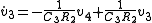
from which state equations can be formed:
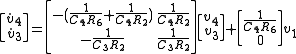 .
.
or a lever
.
Denoted
r
e1 .. e2
------- TF ------
f1 f2
where the r denotes the modulus of the transformer. This means
and .
.
relates flow to effort. It also adds no power and is written
e1 μ e2
------- GY ------
f1 f2
meaning that
and .
.
Graph (mathematics)
In mathematics, a graph is an abstract representation of a set of objects where some pairs of the objects are connected by links. The interconnected objects are represented by mathematical abstractions called vertices, and the links that connect some pairs of vertices are called edges...
of a physical dynamic system
Dynamical system
A dynamical system is a concept in mathematics where a fixed rule describes the time dependence of a point in a geometrical space. Examples include the mathematical models that describe the swinging of a clock pendulum, the flow of water in a pipe, and the number of fish each springtime in a...
. It is similar to the better known block diagram
Block diagram
Block diagram is a diagram of a system, in which the principal parts or functions are represented by blocks connected by lines, that show the relationships of the blocks....
and signal-flow graph
Signal-flow graph
A signal-flow graph is a special type of block diagram—and directed graph—consisting of nodes and branches. Its nodes are the variables of a set of linear algebraic relations. An SFG can only represent multiplications and additions. Multiplications are represented by the weights of the branches;...
, with the major difference that the arcs in bond graphs represent bi-directional exchange of physical energy
Energy
In physics, energy is an indirectly observed quantity. It is often understood as the ability a physical system has to do work on other physical systems...
, while those in block diagrams and signal-flow graphs represent uni-directional
Directed graph
A directed graph or digraph is a pair G= of:* a set V, whose elements are called vertices or nodes,...
flow of information. Also, bond graphs are multi domain and domain neutral. This means a bond graph can incorporate multiple domains seamlessly.
The Bond Graph is composed of the "bonds" which link together "single port", "double port" and "multi port" elements (see below for details). Each bond represents the instantaneous flow of energy (dE/dt) or power. The flow in each bond is denoted a pair of variables called 'power variables' whose product is the instantaneous power of the bond. For example, the bond of an electrical system would represent the flow of electrical energy and the power variables would be voltage and current, whose product is power. Each domain's power variables are broken into two types: "effort" and "flow". Effort multiplied by flow produces power, thus the term power variables. Every domain has a pair of power variables with a corresponding effort and flow variable. Examples of effort include force, torque, voltage, or pressure; while flow examples include velocity, current, and volumetric flow. The table below contains the most common energy domains and the corresponding "effort" and "flow".
A bond has two other features described briefly here, and discussed in more detail below. One is the "half-arrow" sign convention. This defines the assumed direction of positive energy flow. As with electrical circuit diagrams and free-body diagrams, the choice of positive direction is arbitrary, with the caveat that the analyst must be consistent throughout with the chosen definition. The other feature is the "causal stroke". This is a vertical bar placed on only one end of the bond. It is not arbitrary. As described below, there are rules for assigning the proper causality to a given port, and rules for the precedence among ports. Any port (single, double or multi) attached to the bond shall specify either "effort" or "flow" by its causal stroke, but not both. The port attached to the end of the bond with the "causal stroke" specifies the "flow" of the bond. And the bond imposes "effort" upon that port. Equivalently, the port on the end without the "causal stroke" imposes "effort" to the bond, while the bond imposes "flow" to that port. This is made more clear with the illustrative examples below.
| Energy Domain | effort | e symbol | e unit (metric) | e unit (imperial) | flow | f symbol | f unit (metric) | f unit (imperial) |
|---|---|---|---|---|---|---|---|---|
| Mechanical, translation | Force | F | N | lb | Linear velocity | v | m/s | ft/s, mph |
| Mechanical, rotation | Torque | τ | N·m | ft·lb | Angular velocity | ω | rad/s | rad/s |
| Electrical | Electromotive force | V or u | V | V | Current | I or i | A | A |
| Magnetic | Magnetomotive force | Flux rate | ||||||
| Hydraulic | Pressure | P | Pa | psi | Volumetric flow rate | Q | m³/s | ft^3/s |
| Thermal | temperature | T | °C or K | °F | entropy flow rate | S | W/°C | ft·lb/s·°F |
If the dynamics of the physical system to be modeled operate on widely varying time scales, fast continuous-time behaviors can be modeled as instantaneous phenomena by using a hybrid bond graph
Hybrid bond graph
A hybrid bond graph is a graphical description of a physical dynamic system with discontinuities . Similar toa regular bond graph, it is an energy-based technique...
.
History
The Bond Graph was invented by Henry PaynterHenry Paynter
Henry M. Paynter is known worldwide as the inventor of bond graphs.- Bond graphs :Bond graphs are a unique way of describing dynamic models, designed to model the interaction between different kinds of physical systems, like electrical, mechanical, hydraulical and chemical...
.. The term "Bond Graph" comes from the fact that many of these graphs look like the bonds in chemistry; an example of this structure is shown in the 'examples' section of this wiki..
Basics
The fundamental idea of a bond graph is that powerPower (physics)
In physics, power is the rate at which energy is transferred, used, or transformed. For example, the rate at which a light bulb transforms electrical energy into heat and light is measured in watts—the more wattage, the more power, or equivalently the more electrical energy is used per unit...
is transmitted between connected components by a combination of "effort" and "flow" (generalized effort & generalized flow). Refer to the table above for examples of effort and flow in different domains. If an engine is connected to a wheel through a shaft, the power is being transmitted in the rotational mechanical domain, meaning the effort and the flow are torque (τ) and angular velocity (ω) respectively. A word bond graph is a first step towards a bond graph, in which words define the components. As a word bond graph, this system would look like:
τ
engine ---------- wheel
ω
A half-arrow is used to provide a sign convention, so if the engine is doing work when τ and ω are positive, then the diagram would be drawn:
τ
engine ---------- wheel
ω /
A full arrow is used to indicate a measurement, and are referred to as signal bonds, because the amount of power flowing through the bond is insignificant. However, it may be useful to certain physical components. For example, the power required to activate a relay is orders of magnitude smaller than the power through the relay itself; making it relevant only to convey whether the switch is on, not the power consumed by it.
\
wheel ---------- tachometer
ω /
Junctions
Power bonds may join at one of two kinds of junctions: a 0 junction and a 1 junction.- In a 0 junction, the flow sums to zero and the efforts are equal. This corresponds to a node in an electrical circuit (where Kirchhoff's current law applies), or to a mechanical "stack" in which all the forces are equal.
- In a 1 junction, the efforts sum to zero and the flows are equal. This corresponds to an electrical loop, or to a forceForceIn physics, a force is any influence that causes an object to undergo a change in speed, a change in direction, or a change in shape. In other words, a force is that which can cause an object with mass to change its velocity , i.e., to accelerate, or which can cause a flexible object to deform...
balance at a mass in a mechanical system.
For an example of a 1 junction, consider a resistor in series:
v1 ---\/\/\/\---v2
i1 R i2=i1
In this case, the flow (current) is constrained to be the same at all points, and when the implied current return path is included the efforts sum to zero. Power can be computed at points 1 and 2, and in general some power will be dissipated in the resistor. As a bond graph, this becomes
R
|\
v1 | v2
------ 1 ------
i1 / i2 /
From an electrical point of view, this diagram may seem counterintuitive in that flow is not preserved in the same way across the diagram. It may be helpful to consider the 1 junction as daisy chain
Daisy chain (electrical engineering)
In electrical and electronic engineering a daisy chain is a wiring scheme in which multiple devices are wired together in sequence or in a ring...
ing the bonds it connects to and power bond up to the R as a resistor with a lead returning back down, so the above is equivalent to
R
+\/\/\+
\ /
| |
v1 | | v2
------+ +------
i1 i2
Regardless of the problem domain, bond graph modeling typically proceeds from the identification of key 1 and 0 junctions associated with identifiable efforts and flows in the system, then identifying the dissipative (R) and storage elements (L and C), power sources, and drawing bonds wherever power or information flow between the sources, junctions, and storage/dissipative components. Then sign conventions (arrow heads), and causality are assigned, and finally equations describing the behavior of the system can be derived using the graph as a kind of guide or map.
Causality
Bond graphs have a notion of causality, indicating which side of a bond determines the instantaneous effort and which determines the instantaneous flow. In formulating the dynamic equations that describe the system, causality defines, for each modeling element, which variable is dependent and which is independent. By propagating the causation graphically from one modeling element to the other, analysis of large-scale models becomes easier. Completing causal assignment in a bond graph model will allow the detection of modeling situation where an algebraic loop exists; that is the situation when a variable is defined recursively as a function of itself.As an example of causality, consider a capacitor in series with a battery. It is not physically possible to charge a capacitor instantly, so anything connected in parallel with a capacitor will necessarily have the same voltage (effort variable) as the capacitor. Similarly, an inductor cannot change flux instantly and so any component in series with an inductor will necessarily have the same flow as the inductor. Because capacitors and inductors are passive devices, they cannot maintain their respective voltage and flow indefinitely—the components to which they are attached will affect their respective voltage and flow, but only indirectly by affecting their current and voltage respectively.
Note: Causality is a symmetric relationship. When one side "causes" effort, the other side "causes" flow.
Active components such as an ideal voltage or current source are also causal.
In bond graph notation, a causal stroke may be added to one end of the power bond to indicate that the opposite end is defining the effort. Consider a constant-torque motor driving a wheel. That would be drawn as follows:
motor τ \|
SE ----------| wheel
ω |
Symmetrically, the side with the causal stroke (in this case the wheel) defines the flow for the bond.
Causality results in compatibility constraints. Clearly only one end of a power bond can define the effort and so only one end of a bond can have a causal stroke. In addition, the two passive components with time-dependent behavior, I and C, can only have one sort of causation: an I component determines flow; a C component defines effort. So from a junction, J, the only legal configurations for I and C are
\|
J -------| I
|
and
| \
J |------- C
|
A resistor has no time-dependent behavior: you can apply a voltage and get a flow instantly, or apply a flow and get a voltage instantly, thus a resistor can be at either end of a causal bond:
\| | \
| |
Sources of flow define flow, sources of effort define effort. Transformers are passive, neither dissipating nor storing energy, so causality passes through them:
| .. | | .. |
------| TF -----| or |------ TF |------
| | | |
A gyrator transforms flow to effort and effort to flow, so if flow is caused on one side, effort is caused on the other side and vice versa:
| .. | | .. |
|------ GY -----| or ------| GY |------
| | | |
Junctions
In a 0-junction, efforts are equal; in a 1-junction, flows are equal. Thus, with causal bonds, only one bond can cause the effort in a 0-junction and only one can cause the flow in a 1-junction. Thus, if the causality of one bond of a junction is known, the causality of the others is also known. That one bond is called the strong bond
___
|
|
|
------| 0 ------|
strong bond ^
|
|
|
---
|
|
|
---
|------ 1 |------
strong bond ^ ___
|
|
|
One can continue, assigning causality using the above rules. Any model which results in inconsistent causality is not physically valid. For example, consider an inductor in series with an ideal current source—a physically impossible configuration. The bond graph would look like
SF ------ 1 ------ I
Assigning causality to the source bond we get:
SF |----- 1 ------ I
Propagating the causality through the junction gives
SF |----- 1 |----- I
But assigning causality to the inductor gives
SF |----- 1 |----| I
which is invalid, because the causality on the right bond is redundant. This ability to automatically identify impossible configurations is a major advantage of bond graphs.
In contrast, one can inadvertently draw an electrical diagram or mechanical schematic that, while possible to construct, would not behave as modeled. For example, one can connect a capacitor directly to a battery, but the assumption that the battery is an ideal voltage source would be violated corresponding with the fact that the theoretical flux would be infinite. The bond graph would tell you that a resistor needs to be put in series with the capacitor to keep the model realistic.
Example
Consider a simple RC circuitRC circuit
A resistor–capacitor circuit ', or RC filter or RC network, is an electric circuit composed of resistors and capacitors driven by a voltage or current source...
:
R
i1 --\/\/\-----+------ i2 →
v1 | v2
C = ↓ic
|
ground ----+------
As a bond graph, the same system looks like
R C
---
|\ |\
| |
---
v1 | | v2 \
Se,in ------| 1 |----- 0 ------- out
i1 /| | / i2 /
Note that the output is assumed to draw no power from the circuit, so a full arrow is used instead of a half-arrow. For the purpose of modeling dynamics, this means the output full bond can be ignored and the diagram is simplified:
R
---
|\
v3 | i3
|
v1 | | v2
S_e,in ------| 1 |----- C
i1 /| | i2 /
is a "source of effort" (voltage source) that forces the dynamics. Note that the causality for a source of effort imposes effort on the junction. To avoid formulating integral equations, the causality stroke for the capacitor must also impose effort on the junction. Since every 1 junction should have exactly one flow causal stroke, bond 3 must show flow imposed by the R element (causal stroke away from 1 junction).To derive the differential equation, start on bond 2 (attached to a reactive element) and write the capacitive relation:
Because bond 2 is attached to a 1 junction (shared flow) where bond 3 determines the flow,
. In turn, following the effort causality on the 1 junction we can write so:Since
is an input, and is a state variable, the equation is completely expanded. For systems with multiple I and/or C elements, the process can be repeated once for each derivative of a state variable and a system of (typically linear) differential equations can be formed.For example, suppose we put two of these in series:
R → i2 R
i1 --\/\/\-----+------------\/\/\-----+------ i3 →
v1 | v2 | v3
C = ↓ic C = ↓ic
| |
ground ----+----------------------+---------
The corresponding bond graph looks like
R C R C
--- ---
|\ |\ |\ |\
6 | 4 | 2 | 3 |
--- ---
1 | | 5 7 | | 8 9 \
SE ------| 1 |------ 0 ------| 1 |------ 0 ------ out
/| | / /| | / /
where the ever-present effort/flow (voltage/current in this case) variables have been dropped and the bonds are simply numbered per typical bond graph convention (in this case the first four numbers were placed to avoid confusion with the signal numbering in the circuit diagram). Again, the output is assumed to draw no power so bonds 8 and 9 can effectively be removed in favor of a direct connection to bond 3:
R C R
--- ---
|\ |\ |\
6 | 4 | 2 |
---
1 | | 5 7 | | 3
SE ------| 1 |------ 0 ------| 1 |------ C
/| | / /| | /
As before, we can start with the derivative of a state variable (v4) and follow the bonds to form equations:
Continuing the expansion:
Grouping by state variables and inputs:
Similarly,
can be obtained:from which state equations can be formed:
.Transformer
A transformer adds no power but transforms it, much as an ideal electrical transformerTransformer
A transformer is a device that transfers electrical energy from one circuit to another through inductively coupled conductors—the transformer's coils. A varying current in the first or primary winding creates a varying magnetic flux in the transformer's core and thus a varying magnetic field...
or a lever
Lever
In physics, a lever is a rigid object that is used with an appropriate fulcrum or pivot point to either multiply the mechanical force that can be applied to another object or resistance force , or multiply the distance and speed at which the opposite end of the rigid object travels.This leverage...
.
Denoted
r
e1 .. e2
------- TF ------
f1 f2
where the r denotes the modulus of the transformer. This means
and
.Gyrator
A gyratorGyrator
A gyrator is a passive, linear, lossless, two-port electrical network element proposed in 1948 by Tellegen as a hypothetical fifth linear element after the resistor, capacitor, inductor and ideal transformer. Unlike the four conventional elements, the gyrator is non-reciprocal...
relates flow to effort. It also adds no power and is written
e1 μ e2
------- GY ------
f1 f2
meaning that
and
.International Conferences on Bond Graph Modeling (ECMS & ICBGM)
A bibliography on Bond Graph modeling may be extracted from the following conferences :- ECMS-2008 22nd European Conference on Modelling and Simulation, June 3 - 6th, 2008 Nicosia, Cyprus
- ICBGM-2007: 8th International Conference on Bond Graph Modeling And Simulation, January 15-17, 2007, San Diego, California, U.S.A.
- ECMS-2006 20TH European Conference on Modelling and Simulation, May 28 - 31st, 2006, Bonn, Germany
- IMAACA-2005 International Mediterranean Modeling Multiconference
- ICBGM-2005 International Conference on Bond Graph Modeling and Simulation, January 23-27, 2005, New Orleans, Louisiana, U.S.A. - Papers
- ICBGM-2003 International Conference on Bond Graph Modeling and Simulation (ICBGM'2003) January 19 - 23, 2003, Orlando, Florida, USA - Papers
- 14TH European Simulation symposium October 23-26, 2002 Dresden, Germany
- ESS'2001 13th European Simulation symposium, Marseilles, France October 18-20th, 2001
- ICBGM-2001 International Conference on Bond Graph Modeling and Simulation (ICBGM 2001), Phoenix, Arizona U.S.A.
- European Simulation Multi-conference 23 - 26 May, 2000, Gent, Belgium
- 11th European Simulation symposium, October 26-28, 1999 Castle, Friedrich-Alexander University,Erlangen-Nuremberg, Germany
- ICBGM-1999 International Conference on Bond Graph Modeling and Simulation January 17-20, 1999 San Francisco, California
- ESS-97 9TH European Simulation Symposium and Exhibition Simulation in Industry, Passau, Germany, October 19-22, 1997
- ICBGM-1997 3rd International Conference on Bond Graph Modeling And Simulation, January 12-15 1997, Sheraton-Crescent Hotel, Phoenix, Arizona
- 11th European Simulation Multiconference Istanbul, Turkey, June 1-4, 1997
- ESM-1996 10th annual European Simulation Multiconference Budapest, Hungary, June 2-6, 1996
- ICBGM-1995 Int. Conf. on Bond Graph Modeling and Simulation (ICBGM’95), January 15–18, 1995,Las Vegas, Nevada.
Further reading
- Paynter, Henry M., Analysis and design of engineering systems, The M.I.T. Press, ISBN 0-262-16004-8.
- Karnopp, Dean C., Margolis, Donald L., Rosenberg, Ronald C., 1990: System dynamics: a unified approach, Wiley, ISBN 0-471-62171-4.
- Thoma, Jean, 1975: Bond graphs: introduction and applications, Elsevier Science, ISBN 0-08-018882-6.
- Gawthrop, Peter J. and Smith, Lorcan P. S., 1996: Metamodelling: bond graphs and dynamic systems, Prentice Hall, ISBN 0-13-489824-9.
- Brown, F. T., 2007: Engineering system dynamics – a unified graph-centered approach, Taylor & Francis, ISBN 0-8493-9648-4.
- Amalendu Mukherjee, Ranjit Karmakar (1999): Modeling and Simulation of Engineering Systems Through Bondgraphs CRC Press LLC, 2000 N.W. Corporate Blvd., Boca Raton, Florida 33431. ISBN 978-0849309823
- Gawthrop, P. J. and Ballance, D. J., 1999: Symbolic computation for manipulation of hierarchical bond graphs in Symbolic Methods in Control System Analysis and Design, N. Munro (ed), IEE, London, ISBN 0-85296-943-0.
- Borutzky, Wolfgang, 2010: Bond Graph Methodology, Springer, ISBN 978-1-84882-881-0.
External links
- Complete Bond Graph Overview
- CAMP-G Bond Graph Software
- 20-sim Bond Graph Software
- MTT Model Transformation Tools http://mtt.sourceforge.net
- SYMBOLS Shakti SYstem Modeling by BOnd graph Language and Simulation *BROKEN*
- MathematicaMathematicaMathematica is a computational software program used in scientific, engineering, and mathematical fields and other areas of technical computing...
Bond Graph Toolbox allows bond graph design, analysis and simulation in a native symbolic environment http://www.virtualdynamics.com/softwares.html - Bond Graph library BG V. 2.1 Simulink add-on block library for easy simulation, design and analysis using LTI viewer
- libBondGraph C++ library to create and simulate standard and hybrid bond graph
- texBondGraph Class to draw bond graphs in LaTeX documents