
Thévenin's theorem
Encyclopedia
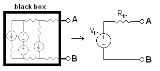
In circuit theory, Thévenin's theorem for linear electrical network
s states that any combination of voltage source
s, current source
s, and resistor
s with two terminals is electrically equivalent to a single voltage source V and a single series resistor R. For single frequency AC systems the theorem can also be applied to general impedance
s, not just resistors. The theorem was first discovered by German scientist Hermann von Helmholtz
in 1853, but was then rediscovered in 1883 by French telegraph engineer Léon Charles Thévenin
(1857–1926).
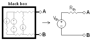
This theorem states that a circuit of voltage sources and resistors can be converted into a Thévenin equivalent, which is a simplification technique used in circuit analysis. The Thévenin equivalent can be used as a good model for a power supply or battery (with the resistor representing the internal impedance and the source representing the electromotive force
). The circuit consists of an ideal voltage source
in series with an ideal resistor
.
are required. These two equations are usually obtained by using the following steps, but any conditions placed on the terminals of the circuit should also work:
The equivalent circuit is a voltage source with voltage VTh in series with a resistance RTh.
Step 2 could also be thought of as:
The Thévenin-equivalent voltage is the voltage at the output terminals of the original circuit. When calculating a Thévenin-equivalent voltage, the voltage divider principle is often useful, by declaring one terminal to be Vout and the other terminal to be at the ground point.
The Thévenin-equivalent resistance is the resistance measured across points A and B "looking back" into the circuit. It is important to first replace all voltage- and current-sources with their internal resistances. For an ideal voltage source, this means replace the voltage source with a short circuit. For an ideal current source, this means replace the current source with an open circuit. Resistance can then be calculated across the terminals using the formulae for series and parallel circuits
. This method is valid only for circuits with independent sources. If there are dependent sources in the circuit, another method must be used such as connecting a test source across A and B and calculating the voltage across or current through the test source.
In the example, calculating the equivalent voltage:
Electrical network
An electrical network is an interconnection of electrical elements such as resistors, inductors, capacitors, transmission lines, voltage sources, current sources and switches. An electrical circuit is a special type of network, one that has a closed loop giving a return path for the current...
s states that any combination of voltage source
Voltage source
In electric circuit theory, an ideal voltage source is a circuit element where the voltage across it is independent of the current through it. A voltage source is the dual of a current source. In analysis, a voltage source supplies a constant DC or AC potential between its terminals for any current...
s, current source
Current source
A current source is an electrical or electronic device that delivers or absorbs electric current. A current source is the dual of a voltage source. The term constant-current sink is sometimes used for sources fed from a negative voltage supply...
s, and resistor
Resistor
A linear resistor is a linear, passive two-terminal electrical component that implements electrical resistance as a circuit element.The current through a resistor is in direct proportion to the voltage across the resistor's terminals. Thus, the ratio of the voltage applied across a resistor's...
s with two terminals is electrically equivalent to a single voltage source V and a single series resistor R. For single frequency AC systems the theorem can also be applied to general impedance
Electrical impedance
Electrical impedance, or simply impedance, is the measure of the opposition that an electrical circuit presents to the passage of a current when a voltage is applied. In quantitative terms, it is the complex ratio of the voltage to the current in an alternating current circuit...
s, not just resistors. The theorem was first discovered by German scientist Hermann von Helmholtz
Hermann von Helmholtz
Hermann Ludwig Ferdinand von Helmholtz was a German physician and physicist who made significant contributions to several widely varied areas of modern science...
in 1853, but was then rediscovered in 1883 by French telegraph engineer Léon Charles Thévenin
Léon Charles Thévenin
Léon Charles Thévenin was a French telegraph engineer who extended Ohm's law to the analysis of complex electrical circuits.- Background :...
(1857–1926).
This theorem states that a circuit of voltage sources and resistors can be converted into a Thévenin equivalent, which is a simplification technique used in circuit analysis. The Thévenin equivalent can be used as a good model for a power supply or battery (with the resistor representing the internal impedance and the source representing the electromotive force
Electromotive force
In physics, electromotive force, emf , or electromotance refers to voltage generated by a battery or by the magnetic force according to Faraday's Law, which states that a time varying magnetic field will induce an electric current.It is important to note that the electromotive "force" is not a...
). The circuit consists of an ideal voltage source
Voltage source
In electric circuit theory, an ideal voltage source is a circuit element where the voltage across it is independent of the current through it. A voltage source is the dual of a current source. In analysis, a voltage source supplies a constant DC or AC potential between its terminals for any current...
in series with an ideal resistor
Resistor
A linear resistor is a linear, passive two-terminal electrical component that implements electrical resistance as a circuit element.The current through a resistor is in direct proportion to the voltage across the resistor's terminals. Thus, the ratio of the voltage applied across a resistor's...
.
Calculating the Thévenin equivalent
To calculate the equivalent circuit, the resistance and voltage are needed, so two equationsSimultaneous equations
In mathematics, simultaneous equations are a set of equations containing multiple variables. This set is often referred to as a system of equations. A solution to a system of equations is a particular specification of the values of all variables that simultaneously satisfies all of the equations...
are required. These two equations are usually obtained by using the following steps, but any conditions placed on the terminals of the circuit should also work:
- Calculate the output voltage, VAB, when in open circuitOpen-circuit voltageOpen-circuit voltage is the difference of electrical potential between two terminals of a device when there is no external load connected, i.e. the circuit is broken or open. Under these conditions there is no external electric current between the terminals, even though there may be current...
condition (no load resistorExternal electric loadIf an electric circuit has a well-defined output terminal, the circuit connected to this terminal is the load....
—meaning infinite resistance). This is VTh. - Calculate the output current, IAB, when the output terminals are short circuitShort circuitA short circuit in an electrical circuit that allows a current to travel along an unintended path, often where essentially no electrical impedance is encountered....
ed (load resistance is 0). RTh equals VTh divided by this IAB.
The equivalent circuit is a voltage source with voltage VTh in series with a resistance RTh.
Step 2 could also be thought of as:
- 2a. Replace voltage sources with short circuits, and current sources with open circuits.
- 2b. Calculate the resistance between terminals A and B. This is RTh.
The Thévenin-equivalent voltage is the voltage at the output terminals of the original circuit. When calculating a Thévenin-equivalent voltage, the voltage divider principle is often useful, by declaring one terminal to be Vout and the other terminal to be at the ground point.
The Thévenin-equivalent resistance is the resistance measured across points A and B "looking back" into the circuit. It is important to first replace all voltage- and current-sources with their internal resistances. For an ideal voltage source, this means replace the voltage source with a short circuit. For an ideal current source, this means replace the current source with an open circuit. Resistance can then be calculated across the terminals using the formulae for series and parallel circuits
Series and parallel circuits
Components of an electrical circuit or electronic circuit can be connected in many different ways. The two simplest of these are called series and parallel and occur very frequently. Components connected in series are connected along a single path, so the same current flows through all of the...
. This method is valid only for circuits with independent sources. If there are dependent sources in the circuit, another method must be used such as connecting a test source across A and B and calculating the voltage across or current through the test source.
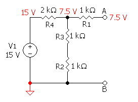
Example
 |
 |
 |
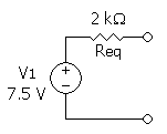 |
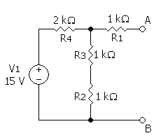
In the example, calculating the equivalent voltage:
-

(notice that R1 is not taken into consideration, as above calculations are done in an open circuit condition between A and B, therefore no current flows through this part, which means there is no current through R1 and therefore no voltage drop along this part)
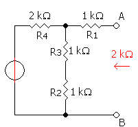
Calculating equivalent resistance:
-

-
-

-
-

Conversion to a Norton equivalent
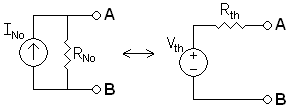
A Norton equivalent circuitNorton's theoremNorton's theorem for linear electrical networks, known in Europe as the Mayer–Norton theorem, states that any collection of voltage sources, current sources, and resistors with two terminals is electrically equivalent to an ideal current source, I, in parallel with a single resistor, R...
is related to the Thévenin equivalent by the following:


Practical limitations
- Many, if not most circuits are only linear over a certain range of values, thus the Thévenin equivalent is valid only within this linear range and may not be valid outside the range.
- The Thévenin equivalent has an equivalent I-V characteristic only from the point of view of the load.
- The power dissipation of the Thévenin equivalent is not necessarily identical to the power dissipation of the real system. However, the power dissipated by an external resistor between the two output terminals is the same regardless of how the internal circuit is represented.
See also
- Superposition theoremSuperposition theoremThe superposition theorem for electrical circuits states that the response in any branch of a bilateral linear circuit having more than one independent source equals the algebraic sum of the responses caused by each independent source acting alone, while all other independent sources are replaced...
- Extra element theoremExtra element theoremThe Extra Element Theorem is an analytic technique developed by R.D. Middlebrook for simplifying the process of deriving driving point and transfer functions for linear electronic circuits...
- Source transformationSource transformationFinding a solution to a circuit can be somewhat difficult without using tricks or methods that make the circuit appear simpler. Circuit solutions are often simplified, especially with mixed sources, by transforming a voltage into a current source, and vice versa...
- Edward Lawry NortonEdward Lawry NortonEdward Lawry Norton was an accomplished Bell Labs engineer and scientist famous for developing the concept of the Norton equivalent circuit. He attended the University of Maine for two years before transferring to M.I.T. and received a S.B. degree in 1922. He received an M.A...
External links
- Origins of the equivalent circuit concept
- Thevenin's theorem at allaboutcircuits.com
- ECE 209: Review of Circuits as LTI Systems — At end, shows application of Thévenin's theorem that turns complicated circuit into a simple first-order low-pass filterLow-pass filterA low-pass filter is an electronic filter that passes low-frequency signals but attenuates signals with frequencies higher than the cutoff frequency. The actual amount of attenuation for each frequency varies from filter to filter. It is sometimes called a high-cut filter, or treble cut filter...
voltage divider with obvious time constantTime constantIn physics and engineering, the time constant, usually denoted by the Greek letter \tau , is the risetime characterizing the response to a time-varying input of a first-order, linear time-invariant system.Concretely, a first-order LTI system is a system that can be modeled by a single first order...
and gainGainIn electronics, gain is a measure of the ability of a circuit to increase the power or amplitude of a signal from the input to the output. It is usually defined as the mean ratio of the signal output of a system to the signal input of the same system. It may also be defined on a logarithmic scale,...
.
-
-
-
-
-