
MetroWest Water Supply Tunnel
Encyclopedia
The MetroWest Water Supply Tunnel (MWWST) is an advanced underground aqueduct that supplies potable water to residents of much of Greater Boston
. It is part of the Massachusetts Water Resources Authority
(MWRA) water supply system.
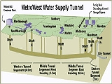
This aqueduct starts at the John J. Carroll Water Treatment Plant in Marlborough, Massachusetts
and ends at an MWRA terminal in Weston, Massachusetts
. It is about 17.6 miles (28.3 km) long (28.3 km) and is constructed far below ground level, mostly in bedrock. It includes several vertical risers called shafts, lined with steel, used to make connections throughout the system. It is built underneath portions of Marlborough
, Southborough
, Framingham
, Wayland
, and Weston
Massachusetts, with a wye intersection 235 feet (71.6 m) below the Massachusetts Turnpike
toll booths at State route 128
.
After fewer than 7 years of service,on the morning of May 1st 2010 the tunnel's connection to the city tunnel extension failed, dumping its full capacity of 8 million gallons per hour into the Charles river and forcing 2 million water customers in Boston and surrounding communities to boil water before drinking it. Emergency supplies from such locations as the Chestnut Hill Reservoir are exposed to air and are therefore susceptible to contamination by animal waste.
Greater Boston
Greater Boston is the area of the Commonwealth of Massachusetts surrounding the city of Boston. Due to ambiguity in usage, the size of the area referred to can be anywhere between that of the metropolitan statistical area of Boston and that of the city's combined statistical area which includes...
. It is part of the Massachusetts Water Resources Authority
Massachusetts Water Resources Authority
The Massachusetts Water Resources Authority is a public authority in the Commonwealth of Massachusetts that provides wholesale drinking water and sewage services to certain municipalities and industrial users in the state, primarily in the Boston area.The authority receives water from the Quabbin...
(MWRA) water supply system.
This aqueduct starts at the John J. Carroll Water Treatment Plant in Marlborough, Massachusetts
Marlborough, Massachusetts
Marlborough is a city in Middlesex County, Massachusetts, United States. The population was 38,499 at the 2010 census. Marlborough became a prosperous industrial town in the 19th century and made the transition to high technology industry in the late 20th century after the construction of the...
and ends at an MWRA terminal in Weston, Massachusetts
Weston, Massachusetts
Weston is a suburb of Boston located in Middlesex County, Massachusetts, United States in the Boston metro area. The population of Weston, according to the 2010 U.S. Census, is 11,261....
. It is about 17.6 miles (28.3 km) long (28.3 km) and is constructed far below ground level, mostly in bedrock. It includes several vertical risers called shafts, lined with steel, used to make connections throughout the system. It is built underneath portions of Marlborough
Marlborough, Massachusetts
Marlborough is a city in Middlesex County, Massachusetts, United States. The population was 38,499 at the 2010 census. Marlborough became a prosperous industrial town in the 19th century and made the transition to high technology industry in the late 20th century after the construction of the...
, Southborough
Southborough, Massachusetts
Southborough is an affluent town in Worcester County, Massachusetts, United States. It incorporates the smaller villages of Cordaville, Fayville, and Southville. Its name is often informally shortened to Southboro, a usage seen on many area signs and maps. Its population was 9,767 at the 2010...
, Framingham
Framingham, Massachusetts
Framingham is a New England town in Middlesex County, Massachusetts, United States. The population was 68,318 as of the United States 2010 Census. -History:...
, Wayland
Wayland, Massachusetts
Wayland is a town in Middlesex County, Massachusetts, United States. The population was 12,994 at the 2010 census.For geographic and demographic information on Cochituate, which is part of Wayland, please see the article Cochituate, Massachusetts.-History:...
, and Weston
Weston, Massachusetts
Weston is a suburb of Boston located in Middlesex County, Massachusetts, United States in the Boston metro area. The population of Weston, according to the 2010 U.S. Census, is 11,261....
Massachusetts, with a wye intersection 235 feet (71.6 m) below the Massachusetts Turnpike
Massachusetts Turnpike
The Massachusetts Turnpike is the easternmost stretch of Interstate 90. The Turnpike begins at the western border of Massachusetts in West Stockbridge connecting with the Berkshire Connector portion of the New York State Thruway...
toll booths at State route 128
Route 128 (Massachusetts)
Route 128, also known as the Yankee Division Highway , and originally the Circumferential Highway, is a partial beltway around Boston, Massachusetts, United States. The majority of the highway is built to freeway standards, and about 3/5 of it is part of the Interstate Highway System...
.
History
In 1989, the Massachusetts Water Resources Authority (MWRA) issued a planning and design contract for a second transmission main to provide redundancy for the Hultman Aqueduct. As originally conceived, the project consisted of a tunnel combined with reconstruction of the Sudbury Aqueduct, a 19th century construction that had been taken out of service in 1974. During feasibility studies, it was recognized that costs and environmental and community impact issues related to reconstruction of the Sudbury Aqueduct through an urban/suburban area compared unfavorably with a full length tunnel in rock, deep under existing structures and facilities. The alignment of the tunnel generally coincides with the existing Hultman Aqueduct and is constructed in permanent underground easements below several hundred private properties. The full length, unreinforced concrete lined, pressure tunnel design concept was selected and the facility was named the MetroWest Water Supply Tunnel.After fewer than 7 years of service,on the morning of May 1st 2010 the tunnel's connection to the city tunnel extension failed, dumping its full capacity of 8 million gallons per hour into the Charles river and forcing 2 million water customers in Boston and surrounding communities to boil water before drinking it. Emergency supplies from such locations as the Chestnut Hill Reservoir are exposed to air and are therefore susceptible to contamination by animal waste.