

IBM 3705 Communications Controller
Encyclopedia
System/370
The IBM System/370 was a model range of IBM mainframes announced on June 30, 1970 as the successors to the System/360 family. The series maintained backward compatibility with the S/360, allowing an easy migration path for customers; this, plus improved performance, were the dominant themes of the...
. Its purpose was to connect communication lines to the mainframe channel
Channel I/O
In computer science, channel I/O is a generic term that refers to a high-performance input/output architecture that is implemented in various forms on a number of computer architectures, especially on mainframe computers...
. It was a first communications controller
Front end processor
A front end processor , or a communications processor, is a small-sized computer which interfaces to the host computer a number of networks, such as SNA, or a number of peripheral devices, such as terminals, disk units, printers and tape units. Data is transferred between the host computer and the...
of the popular IBM 37xx series. It was announced in March 1972. Designed for semiconductor memory which was not ready at the time of announcement, the 3705-I had to use 1.2 microsecond core storage; the later 3705-II used 1.0 microsecond SRAM. Monolithic System Technology components, similar to those in S/370, were used.
The 3705 normally occupied a single frame two feet wide and three feet deep. Up to three expansion frames could be attached for a theoretical capacity of 352 half-duplex lines and two independent channel adapters.
The 3704 was an entry level version of the 3705 with limited features.
Purpose
IBM intended it to be used in three ways:- Emulation of the older IBM 2703 Communications Controller and its predecessors. The relevant software was the Emulation Program or EP.
- Connection of Systems Network ArchitectureSystems Network ArchitectureSystems Network Architecture is IBM's proprietary networking architecture created in 1974. It is a complete protocol stack for interconnecting computers and their resources. SNA describes the protocol and is, in itself, not actually a program...
(SNA) devices to a mainframe. The relevant software was Network Control Program (NCP). When used in this fashion, the 3705 was considered an SNA PU4. - Combining the two methods above in a configuration called a Partitioned Emulation Program or PEP.
Architecture
The storage word length was 16-bits. The registers had the same width as the address bus. Their length varied between 16, 18 and 20 bits depending on the amount of storage installed. A particular interrupt level had eight registers. Register zero was the program counter which gave the address of the next instruction to be executed; the other seven were accumulators. The four odd-numbered accumulators could be addressed as eight single-byte accumulators.Instructions were fairly simple. Most were register-to-register or register-immediate instructions which executed in a single memory cycle. There were eight storage reference instructions which required two or three storage cycles to complete. The only shift capability was to shift right one or to add a register to itself.
Special hardware assisted in the calculation of a cyclic redundancy check
Cyclic redundancy check
A cyclic redundancy check is an error-detecting code commonly used in digital networks and storage devices to detect accidental changes to raw data...
for detection of transmission errors. Both CRC-16 CCITT and CRC-16 IBM were supported. Assuming the running value was maintained in storage, the execution time to accumulate one more byte was five storage cycles (three instructions).
Rapid context switching was a design objective. The register file was divided into four sections. The three commonly used interrupt levels and the background level had distinct sets of registers. Therefore entry into most interrupt levels did not require saving the registers of the interrupted program. The infrequently used level which processed program and hardware errors shared registers with the next highest level and thus had to save and restore registers.
The five program levels were:
- Error processing
- Communication line events
- Channel adapter events
- Service requests from other levels
- Background level
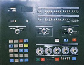
The 3705 had a flashing light style control panel which was superior to most other IBM panels of that style. The two unusual (for IBM) features were:
- Storage (and some external registers) could be displayed while the program was executing.
- The hex input switches and the two register-sized displays could be used by the program while the machine was running. This capability derived from the objective of emulating the IBM 2703 which had a fairly rich control panel.
Peripherals
Three types of peripherals were available: communications scanners, channel adapters and 8" floppy diskFloppy disk
A floppy disk is a disk storage medium composed of a disk of thin and flexible magnetic storage medium, sealed in a rectangular plastic carrier lined with fabric that removes dust particles...
(only available in models without a channel adapter). The first Communication Scanner and the first Channel Adapter occupied the same frame as the CCU. Extra peripherals required extra frames.
Communication Scanners
Three different communication scanners were offered:The Type 1 Communication Scanner was an entry level device which presented an interrupt on every received bit. Transmission also required an interrupt for every bit. In theory this would have allowed for rather imaginative uses such as Morse Code and connection to devices with unusual framing methods. A maximum of 64 half-duplex lines could be attached. The aggregate bandwidth was restricted due to the heavy processing requirements.
The Type II Communication Scanner performed functions similar to a USART. There was an interrupt for every transmitted or received character. Six different asynchronous character formats, two forms of Bisync
Binary Synchronous Communications
Binary Synchronous Communication is an IBM link protocol, announced in 1967 after the introduction of System/360. It replaced the synchronous-transmit-receive protocol used with second generation computers. The intent was that common link management rules could be used with three different...
and HDLC/SDLC
Synchronous Data Link Control
Synchronous Data Link Control is a computer communications protocol. It is the layer 2 protocol for IBM's Systems Network Architecture . SDLC supports multipoint links as well as error correction. It also runs under the assumption that an SNA header is present after the SDLC header...
were supported. A single scanner could attach up to 96 (64 for the first scanner) half-duplex lines. This is the basis of the theoretical maximum capacity of 352 lines. In practice the limit was lower as a scanner with more than 48 half duplex lines could not support any 9600 bit/s lines.
The Type III Communication Scanner was a high performance device for attachment of Bisync
Binary Synchronous Communications
Binary Synchronous Communication is an IBM link protocol, announced in 1967 after the introduction of System/360. It replaced the synchronous-transmit-receive protocol used with second generation computers. The intent was that common link management rules could be used with three different...
and HDLC/SDLC
Synchronous Data Link Control
Synchronous Data Link Control is a computer communications protocol. It is the layer 2 protocol for IBM's Systems Network Architecture . SDLC supports multipoint links as well as error correction. It also runs under the assumption that an SNA header is present after the SDLC header...
lines. It operated on entire frames. DMA
Direct memory access
Direct memory access is a feature of modern computers that allows certain hardware subsystems within the computer to access system memory independently of the central processing unit ....
was used to fetch and store the bytes of a frame. In theory the line attachment capacity was the same as for Type II Communication Scanner (352 line limit). The need to restrict scanner size to 48 lines to support 9600 bit/s was still present. Restricting scanner size to 16 lines allowed line speeds of up to 30,000 bit/s. A scanner size of 8 lines allowed speed of about 60,000 bit/s.
Maximum Communication Line Connection Estimates
With modem supplied clocking, a single line was limited to 56 kbit/s; with internal clocking the limit was 2400 bit/s.Aggregate line connection ability was limited by processing speed.
For a Type II Communications Scanner, processing of a received or transmitted character might take fifty storage cycles (forty instructions). In a 3705-II this gives an aggregate capacity of 20,000 byte/s. This would allow about 160 half-duplex lines running at a mean speed of 120 cps. Alternatively sixteen half-duplex lines running at 1200 cps (9600 bit/s) would be the theoretical limit. IPSANET
IPSANET
IPSANET was a packet switching network written by I. P. Sharp Associates . Operation began in May 1976. It initially used IBM 3705s and Computer Automation LSI-2 computers as nodes. An Intel 80286 based-node was added in 1987. It was called the Beta node.The original purpose was to connect...
experience was that six full-duplex 9600 bit/s lines carrying a heavy load was the limit. IBM software may have had superior performance.
For a Type III Communications Scanner cycle steal processing of a single character was fairly inexpensive—a single storage cycle was required. This would give a theoretical limit of a million cps (eighty 9600 bit/s half-duplex lines). In practice the limit was probably lower as some processing would be required for end of frame. Also if the frame contents were moved about in storage this would require 3.5 storage cycles per byte.
Channel Adapters
Two types of channel adapter were offered:Type 1 and Type 4 Channel Adapters were designed for 270x emulation. They recognized up to 256 channel addresses and transferred data in small bursts (four bytes for the Type 1; 32 bytes maximum for the Type 4). The hardware could accept almost all of the 240 possible channel command codes. Software had to analyse the command from the channel and either reject the command or process it according to specific rules. Interrupt processing required about fifty storage cycles to process a four byte transfer. The 3705 could only have a single Type 1 Adapter but two Type 4 Adapters were permitted.
Type 2 and Type 3 Channel Adapters were designed for NCP use only. Only one device address was recognized. Data transfer was via cycle steal which made the overhead low if large buffers were used. The hardware accepted seven channel commands of which four were completely processed by the adapter. This left a read and two write commands for the software to process. These adapters could be connected to any of the three System/370
System/370
The IBM System/370 was a model range of IBM mainframes announced on June 30, 1970 as the successors to the System/360 family. The series maintained backward compatibility with the S/360, allowing an easy migration path for customers; this, plus improved performance, were the dominant themes of the...
channel types but a block multiplexor channel was preferred. The Type 3 Adapter could be simultaneously operational (but not in mid-command) on two different channels which might be connected to different hosts.
Related Machines
The Amdahl 4705 was compatible with and ran about 2.5 times as fast as a comparable 3705-II. The IBM 3704 was an entry level version of the 3705. It was restricted to 26 half duplex lines (assuming Type 2 Scanner). DMA devices were not supported on the 3704. Performance was about the same as a 3705-I. A 4704 (a 3704-compatible device) was planned, but was never introduced.The Amdahl 4745 was completely and in every respect a logical superset, or a physical subset of the IBM 3745. Whereas the IBM 3745 offered one or two physical processors, and one or two physical buses, both apparently for redundancy, the Amdahl offered one very highly reliable physical processor and one very highly reliable physical bus (but two logical buses), with no apparent need for redundancy. Whereas the IBM 3745 offered two buses, the Amdahl 4745 offered a single bus which throughput capacity exceeded the aggregate throughput capacity of the two buses of the IBM 3745.
The design of the Amdahl 4745 was such that the control program (NCP) could not tell whether it was operating in an IBM 3745 or in an Amdahl 4745 (or, for that matter, in an IBM 3725 or in an Amdahl 4725). Amdahl's logical and physical simulation of the IBM 3745 (IBM 3725) was that complete.
Later, a very high-speed scanner was offered with the Amdahl 4745 (and also with the Amdahl 4725, for which IBM had no such corresponding 3725 offering) which offered increased redundancy over the IBM 4745 very high-speed scanner (1.544 Mb/s, T1, or 2.048 Mb/s, E1).
Demise
The 3705 was eventually replaced by the 3720IBM 3720
The IBM 3720 was a communications controller made by IBM, suitable for use in an IBM System/390. Official service support was withdrawn in 1999 in favour of the IBM 3745. The IBM 3720 is unrelated to the similarly-numbered IBM 3270 display terminal system.-External links:*...
and 3725. The 3745
IBM 3745
The IBM 3745 is the latest and last of a 37xx family of communications controllers for the IBM mainframe environment. As of mid-2009 there were an estimated 7,000+ of the larger 3745 models still in active production status, down from 20,000 or more in 2007...
was similar but not entirely compatible. The 3705 was withdrawn from marketing in December 1985. Hardware maintenance service was withdrawn in January 1999.