
FS class E636
Encyclopedia
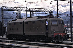
The FS
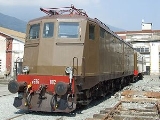
E636 is a class of Italian
articulated electric locomotive
s. They were introduced in the course of the 1940s until the 1960s, and have been decommissioned in 2006. They have been one of the most numerous Italian locomotive group, and have been widely employed during their long career, hauling every type of train, ranging from freight to long range passenger services. Their introduction also saw the employment of some revolutionary (for the time) design concepts, such as the articulated carbody and the three bogies scheme.
 The E636 was designed to overcome the problems showed in the 1930s by both the E626
multi-purpose and E326
high-speed locomotives, in order to better handle the increasing railway traffic in Italy
.
The E636 was the first Italian locomotive adopting the Bo-Bo-Bo
configuration with chassis divided into two articulated parts pivoting on the central bogie
, which is very well suited for the often tortuous lines of Italy and that would have been later repeated on the E645/646
and E656
classes. The presence of a great number of wheels was considered important due to the presence of a number of high-slope lines in the Italian railroad network as it increases the adhesion limit, meaning that the locomotive is less prone to wheel slips. The new engines weighted approximately 101 tons. Engines were initially the same as E626. The 32R used a 3 kV catenary but this was soon shown to be inadequate and so were updated and provided with a new hollow axle transmission system. Mainly two different gear ratios were installed: 21/65 for sloping lines or heavy freight trains (maximum speed of 95 km/h, elevated later to 110 km/h), and the longer 28/65, with a maximum speed of 120 km/h, suited for passenger services.
The locomotive was built in three different series:
The first unit entered service in May 1940. Six locomotives were destroyed during World War II
. After the war the total number of locomotives was brought to 469, also thanks to the support from the Marshall Plan
, and making it one of the most numerous groups of Italian locomotives. All the units were painted with an auburn livery; this was changed in the 1990s to a white one with green stripes for most trains (XMPR livery).
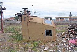
By 2000s railway standards, E636s were old and uncomfortable. The original design of the cockpits proved absolutely unfit to modern safety standards: this was shown in an accident in 1996 at Sulmona
, where the engine driver died despite the low speed, without being able to leave the cockpit in time. 200 units were therefore rebuilt and stripped of all asbestos
.
Starting from 1990s, E636s were used mainly for cargo services, save for the more backlog Sicilian
lines. Some units were lent to minor Italian railroads. The phasing out of the entire class was completed in May 2006.
resistor
s connected in series, for a total resistance of 29 ohm
s) that needs to be gradually, but as soon as possible, excluded on start-ups, which regulates the current to the six 32R-200 DC
traction motors, two per bogie
.
The motors can be connected in three combinations: series, series-parallel and parallel; each combination provides a progressively higher voltage to the motors, therefore increasing the current.
Their set-up is the following:
 The rheostat (connected in series to the traction motors) is necessary because the DC motor has the intrinsic characteristic of absorbing a current inversely proportional to its rotating speed; at high speeds, it absorbs less current. This means that on start the current would be very high, because the only resistance encountered would be only the one offered by motors and internal conductors, which is very low (a short circuit, in practice). The rheostat increases the overall resistance when starting the locomotive, lowering the current and allowing a smoother start.
In S-P and P combinations, the rheostat is divided in three branches connected in parallel; this lowers the overall rheostat equivalent resistance to about 3.5 ohm, while in S combination its elements are all connected in series.
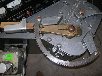
Like almost every Italian locomotive with rheostatic regulation since E626, traction is controlled via a lever (commonly referred to as maniglione) mounted on a support called roncola; this support has several notches, each representing a portion of the rheostat, plus three "end combination" notches and two "transition" positions (a bigger block between the notches).
To accelerate, the driver rotates gradually counterclockwise the lever notch by notch, and in doing so the various rheostat contactors are closed, shunting the resistors and lowering the total rheostat resistance, also allowing more current to the motors; as speed builds up, the counter-electromotive force lowers this current, until the rheostat is no longer necessary: it is, then, totally excluded (obviously if in traction and in an "end combination" notch). This safely allows traction for an indefinite period of time, within certain limits.
When the end combination notches are reached, the driver can then insert the single shunt (one for each combination) or make a transition to the next combination, reintroducing the rheostat which has to be excluded again, for the following combinations until the end of the parallel combination is reached.
The shunts increase the current into the motors by shunting some motor spires (through a contactor in parallel); this reduces the magnetic flux
and, as said, increases the current (since the two are inversely proportional). There are various "shunt levels", depending on the locomotive, as is further explained; usually, there is one per combination.
It is also important to remove the shunts before making a transition, in order to avoid flashes due to anormally high currents.
Like some E626s, E636 locomotives are not provided with the "CEM" motor combiner (CEM stands for Combinatore Escluditore Motori), a device that, during transitions, rotates, combining the motors accordingly through various contactors.
On 636, this is achieved through the uses of more delicate spires, so transitions (especially backward ones) need to be very slow and gradual. The optimal moment to pass to the following/preceding combination first/last notches is when the motor ammeter indicates 0 Ampères, which happens when passing over the transition position with the lever (the driver should briefly stop in the middle of the block and pay attention to the ammeter), meaning that the motor contactors are in optimal position and is safe to proceed. Failure in doing this may result in flashes that will damage the contactors.
An important parameter the driver has to consider, especially during rheostatic exclusion, is the current into the traction circuit.
In particular, if he is excluding too fast, a wheel slippage can occur (in this case the use of sanders and reducing throttle can help), and one or more maximum current relays can open when the maximum allowed current value is exceeded.
The locomotive is protected from overly high currents through different kinds of relay
s:
When they open, they also open the main breaker; that cuts the connection to the catenary.
Before the 1970s, the maximum currents for the relays were the following:
Between 1970 and 1980, the previous values changed:
As can be seen, the currents allowed in series are 450 A in both cases, while in Series-Parallel and Parallel combinations are 350 A and 450 A respectively.
As said, one level of field shunt (percentage of field weakening: 31%) is allowed in each combination; however, some units received 92-250 (used on FS Class E424
) and 32RT-200 type motors which allowed a maximum of 5 levels of field shunts (percentage of field weakening: 65%, 45% on the latters).
These units where later made identical to standard ones again.
All the following built units had the same transmission type of 176-183 but slightly different.
Different locomotives have received various gear ratios (see "Special Units" for more details):
3,000 V
dedicated motors until unit 201; later units have 1 kW motors identical to the ones used on FS Class E646
; they are also used as dynamos to recharge the 24 V batteries (only if line voltage is greater than 1,500 V) used to feed low tension devices (lights, locomotive heating systems, contactors etc.)
Air production on the locomotive was granted by two C38 type compressors; later they were upgraded with the more reliable W242, however, on some units, only one compressor was replaced, leaving one of each type in use on a single locomotive; the C38 produced air until 8 bars in main reservoir tanks were reached, while the W242 from 8 to 9 bars. In fact, on these units, only the W242 was used on normal conditions; the other one only if pressure dropped below 7 bars.
Main-tanks and the 24 V batteries supplies air and current to several systems:
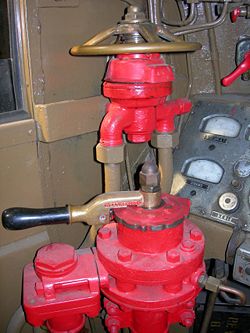
Originally the locomotive mounted a 7-position L-type Westinghouse brake controller and wheel-type locomotive brake, later replaced by the more common Oerlikon FV4 and RA-M2 levers respectively.
 The locomotive has three kinds of brakes:
It is a negative-type brake and is called continuous because it extends itself through the entire train, automatic because if brake continuity is no longer present (general pipe breaks), emergency braking is automatically applied.
On units with Breda-type valves and Oerlikon levers the brakes are graduable during braking and releasing; the working principles are the following.
The braking system of the locomotive is formed by an array of components:
When brakes are released, pressure in the brake pipe is about 5 bars, and 0 bars in brake cylinders.
To brake the train the driver, by moving the brake controller, creates a depression in a particular tank called "", which, through a series of coils creates a connection to the exterior which makes the general pipe to gradually lower its pressure to a value equal to the one present in the aforementioned tank (how fast this happens depends on train length: the longer it is, the slower this procedure will be).
Inside the the command reservoir pressure "wins" over now lower pipe pressure and thus the piston moves, creating a connection between the braking cylinders and the auxiliary reservoir (fed by the main tanks), which will then send a quantity of air to the brake cylinders proportional to the entity of the depression. The maximum pressure that can be reached into the brake cylinders on E636 is 3.8 bar, which corresponds to a pressure inside the general pipe of about 3,5 bars.
In case of emergency braking
, the brake pipe is put to direct communication with outside atmosphere, rapidly dropping pressure, and consequently making the train brake very fastly (though there isn't a variation of braking power: only the braking speed is affected).
To release brakes, the driver makes the pressure rise in the , via the brake controller; the pressure in the brake pipe is restored (air is taken from the main reservoir tanks, and from the main pipe if present) to the value present in the .
Inside the the brake pipe pressure wins over the command reservoir pressure and so the connection between the brake cylinders and the auxiliary tanks is modified (or cut, depending on the pipe pressure); the brake cylinders unload themselves sending their air outside until their pressure reaches a value proportional to the entity of the depression.
When pipe pressure is 5 bars, the cylinders will unload until they are empty.
For a faster brakes' release, it is also possible to briefly "overload" the braking system to a pressure proportional to the depression previously present, up to a maximum pressure of 7.2 bars; shortly after this, the pressure drops to 5.5 bars, and is gradually brought back to 5 bars in about 240 secs.
However, on units with Triple Valves (Distributore tipo Westinghouse) and 7-position levers, braking circuit is slightly different. The is divided in two parts like said before, but there isn't the command reservoir tank: when the pressure inside the brake pipe drops, it's directly the auxiliary reservoir that makes the frame put in the middle moving.
Braking is not gradual on release in this case: when the driver puts the controller on "release" position, brakes are fully released; if he brakes again too shortly after, there is the risk to have a loss of braking power because there may not be enough air to brake optimally, since the absence of the fixed pressure of the command reservoir doesn't ensure that there is enough air to safely release the brakes. It is even possible to fully exhaust the reservoir, with the consequent danger to not be able to stop the train at all. This is prevented in units with Breda and other types of valves as the brakes cannot be fully released if there is not enough air in main reservoir tanks to brake again.
There is a risk associated to the "overload" operation.
Inside the the pressures inside the two chambers are balanced: during the overload both command reservoir and brake pipe pressures rise proportionally.
As said they are gradually lowered back to 5 bars but it may happen that the command reservoir "gets struck" to a higher pressure, while the pipe pressure is lower. This keeps the connection between the auxiliary reservoir and the brake cylinders and consequently the brakes in effect.
In this occurrence a possible solution is to overload again the system so pressures can be rebalanced, or, if this doesn't work, to manually "reset" the command reservoir (emptying it) by pulling a lever located outside.
On units with 7-position levers the risk is greater: the pipe is put to direct connection with the main tanks and, if the controller is left for too much time in the overload position, it may reach a very high pressure (even 9 bars).
It is very easy for the brakes to remain in effect in this case, and the only practicable solution is to manually empty the command reservoir tanks as said above.
 On post war units, 7 mm (0.275590551181102 in) reinforcement frames have been introduced on the chassis and under the cabs, as the first 108 units showed some mechanical weaknesses in those points; in mid 1980s it was decided to reinforce only the chassis on pre-war units (however units 026 an 065 never received these modifications).
To reduce parasite motion, dampers were mounted between the carbodies: glycerine-type from units 1-276 and special-oil type from unit 277 onwards, although these were later eliminated in 1977 because considered useless.
The first 108 units had different rheostat ventilation shafts on the roof than the rest of the units ones, although these were later replaced with the more efficient shafts used on the latter units.
They also had sliding oil-buckles, while following units had rolling bearing ones.
Units 162-171 were equipped with French-derived Athermos buckles for testing purposes, which were later removed.
Sandthrowers were mounted internally into the bogie in the units 001 - 108; after the war they were replaced by external ones that also were natively mounted on later units.
designed by FS engineer Minucciani, that required a periodic acknowledgement from the driver when the train was moving (or emergency braking would have been commanded), but after the war, due to labor union pressures, it was discontinued; however, starting from the 1970s, many (not all) units received "Ripetizione Segnali a 4 codici"
system, Hasler speedometer and a modified "speed graph recorder" (Zona tachigrafica), that also recorded the codes received from the RS.
During the 1960s-1970s Ansaldo-Breda built a locomotive derived from E636 for use in Yugoslavia, classified JŽ 326
.
Ferrovie dello Stato
Ferrovie dello Stato is a government-owned holding which manage infrastructure and service on the Italian rail network. The subsidiary Trenitalia is the main rail operator in Italy.-Organization:Ferrovie dello Stato subsidiaries are:...
E636 is a class of Italian
Italy
Italy , officially the Italian Republic languages]] under the European Charter for Regional or Minority Languages. In each of these, Italy's official name is as follows:;;;;;;;;), is a unitary parliamentary republic in South-Central Europe. To the north it borders France, Switzerland, Austria and...
articulated electric locomotive
Electric locomotive
An electric locomotive is a locomotive powered by electricity from overhead lines, a third rail or an on-board energy storage device...
s. They were introduced in the course of the 1940s until the 1960s, and have been decommissioned in 2006. They have been one of the most numerous Italian locomotive group, and have been widely employed during their long career, hauling every type of train, ranging from freight to long range passenger services. Their introduction also saw the employment of some revolutionary (for the time) design concepts, such as the articulated carbody and the three bogies scheme.
History
FS Class E626
The FS E.625 and E.626 are two classes of Italian electric locomotives produced for the Ferrovie dello Stato. They were introduced in the course of the 1920s and remained in service until the 1990s...
multi-purpose and E326
FS Class E326
The FS E326 was a class of Italian railways electric locomotives. Designed in 1929, they were introduced in the early 1930s, for hauling passenger trains at relatively high speed.-History:...
high-speed locomotives, in order to better handle the increasing railway traffic in Italy
Italy
Italy , officially the Italian Republic languages]] under the European Charter for Regional or Minority Languages. In each of these, Italy's official name is as follows:;;;;;;;;), is a unitary parliamentary republic in South-Central Europe. To the north it borders France, Switzerland, Austria and...
.
The E636 was the first Italian locomotive adopting the Bo-Bo-Bo
Bo-Bo-Bo
thumb|Italian articulated Bo-Bo-Bo [[FS Class E656|E656]] locomotive, [[Rome]], June 2, 2006.A Bo-Bo-Bo in UIC classification is a locomotive with three independent two-axle bogies with all axles powered...
configuration with chassis divided into two articulated parts pivoting on the central bogie
Bogie
A bogie is a wheeled wagon or trolley. In mechanics terms, a bogie is a chassis or framework carrying wheels, attached to a vehicle. It can be fixed in place, as on a cargo truck, mounted on a swivel, as on a railway carriage/car or locomotive, or sprung as in the suspension of a caterpillar...
, which is very well suited for the often tortuous lines of Italy and that would have been later repeated on the E645/646
FS class E646
The FS E645 and E646 are two classes of similar electric locomotives used on Italian railways. They were introduced during the 1950s and they have been retired in 2009.- History :...
and E656
FS Class E656
The Class E656 is an Italian articulated rheostatic-type electric locomotive built from 1973 to 1989. An evolution of the E646/5, they are all-purpose locomotives, and have been used on every kind of train, ranging from freight to intercity passenger trasport.The E656 is nicknamed "Caimano" .-...
classes. The presence of a great number of wheels was considered important due to the presence of a number of high-slope lines in the Italian railroad network as it increases the adhesion limit, meaning that the locomotive is less prone to wheel slips. The new engines weighted approximately 101 tons. Engines were initially the same as E626. The 32R used a 3 kV catenary but this was soon shown to be inadequate and so were updated and provided with a new hollow axle transmission system. Mainly two different gear ratios were installed: 21/65 for sloping lines or heavy freight trains (maximum speed of 95 km/h, elevated later to 110 km/h), and the longer 28/65, with a maximum speed of 120 km/h, suited for passenger services.
The locomotive was built in three different series:
- 1st series (001-108), from 1940 to 1942
- 2nd series (109-243), from 1952 to 1956
- 3rd series (244-469), from 1957 to 1962
The first unit entered service in May 1940. Six locomotives were destroyed during World War II
World War II
World War II, or the Second World War , was a global conflict lasting from 1939 to 1945, involving most of the world's nations—including all of the great powers—eventually forming two opposing military alliances: the Allies and the Axis...
. After the war the total number of locomotives was brought to 469, also thanks to the support from the Marshall Plan
Marshall Plan
The Marshall Plan was the large-scale American program to aid Europe where the United States gave monetary support to help rebuild European economies after the end of World War II in order to combat the spread of Soviet communism. The plan was in operation for four years beginning in April 1948...
, and making it one of the most numerous groups of Italian locomotives. All the units were painted with an auburn livery; this was changed in the 1990s to a white one with green stripes for most trains (XMPR livery).
By 2000s railway standards, E636s were old and uncomfortable. The original design of the cockpits proved absolutely unfit to modern safety standards: this was shown in an accident in 1996 at Sulmona
Sulmona
thumb|150px|Celestine V's hermitage and the remains of the Shrine of Hercules Curinus.thumb|150px|Palazzo SS. Annunziata and Museo Civicothumb|150px|Church of SS...
, where the engine driver died despite the low speed, without being able to leave the cockpit in time. 200 units were therefore rebuilt and stripped of all asbestos
Asbestos
Asbestos is a set of six naturally occurring silicate minerals used commercially for their desirable physical properties. They all have in common their eponymous, asbestiform habit: long, thin fibrous crystals...
.
Starting from 1990s, E636s were used mainly for cargo services, save for the more backlog Sicilian
Sicily
Sicily is a region of Italy, and is the largest island in the Mediterranean Sea. Along with the surrounding minor islands, it constitutes an autonomous region of Italy, the Regione Autonoma Siciliana Sicily has a rich and unique culture, especially with regard to the arts, music, literature,...
lines. Some units were lent to minor Italian railroads. The phasing out of the entire class was completed in May 2006.
Technical details
E636 are very simple locomotives. Most functions of the main command circuit are accomplished through various relays and contactors. In case of failure the train driver could easily fix them to at least free the tracks; also, especially in last years of their service, E636s were the first locomotives that the new train drivers studied during their training courses, due to their simple working mechanics.Motors and electrical description
As most older Italian locomotives, E636 has a rheostat (formed by 16 cast ironCast iron
Cast iron is derived from pig iron, and while it usually refers to gray iron, it also identifies a large group of ferrous alloys which solidify with a eutectic. The color of a fractured surface can be used to identify an alloy. White cast iron is named after its white surface when fractured, due...
resistor
Resistor
A linear resistor is a linear, passive two-terminal electrical component that implements electrical resistance as a circuit element.The current through a resistor is in direct proportion to the voltage across the resistor's terminals. Thus, the ratio of the voltage applied across a resistor's...
s connected in series, for a total resistance of 29 ohm
Ohm
The ohm is the SI unit of electrical resistance, named after German physicist Georg Simon Ohm.- Definition :The ohm is defined as a resistance between two points of a conductor when a constant potential difference of 1 volt, applied to these points, produces in the conductor a current of 1 ampere,...
s) that needs to be gradually, but as soon as possible, excluded on start-ups, which regulates the current to the six 32R-200 DC
Direct current
Direct current is the unidirectional flow of electric charge. Direct current is produced by such sources as batteries, thermocouples, solar cells, and commutator-type electric machines of the dynamo type. Direct current may flow in a conductor such as a wire, but can also flow through...
traction motors, two per bogie
Bogie
A bogie is a wheeled wagon or trolley. In mechanics terms, a bogie is a chassis or framework carrying wheels, attached to a vehicle. It can be fixed in place, as on a cargo truck, mounted on a swivel, as on a railway carriage/car or locomotive, or sprung as in the suspension of a caterpillar...
.
The motors can be connected in three combinations: series, series-parallel and parallel; each combination provides a progressively higher voltage to the motors, therefore increasing the current.
Their set-up is the following:
| Combination | Motor set-up | Voltage per motor |
|---|---|---|
| Series | All motors are connected in series | 500 V |
| Series-Parallel | Two branches of three motors | 1000 V |
| Parallel | Three branches of two motors | 1500 V |
In S-P and P combinations, the rheostat is divided in three branches connected in parallel; this lowers the overall rheostat equivalent resistance to about 3.5 ohm, while in S combination its elements are all connected in series.
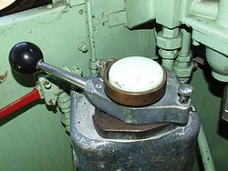
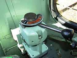
Like almost every Italian locomotive with rheostatic regulation since E626, traction is controlled via a lever (commonly referred to as maniglione) mounted on a support called roncola; this support has several notches, each representing a portion of the rheostat, plus three "end combination" notches and two "transition" positions (a bigger block between the notches).
To accelerate, the driver rotates gradually counterclockwise the lever notch by notch, and in doing so the various rheostat contactors are closed, shunting the resistors and lowering the total rheostat resistance, also allowing more current to the motors; as speed builds up, the counter-electromotive force lowers this current, until the rheostat is no longer necessary: it is, then, totally excluded (obviously if in traction and in an "end combination" notch). This safely allows traction for an indefinite period of time, within certain limits.
When the end combination notches are reached, the driver can then insert the single shunt (one for each combination) or make a transition to the next combination, reintroducing the rheostat which has to be excluded again, for the following combinations until the end of the parallel combination is reached.
The shunts increase the current into the motors by shunting some motor spires (through a contactor in parallel); this reduces the magnetic flux
Magnetic flux
Magnetic flux , is a measure of the amount of magnetic B field passing through a given surface . The SI unit of magnetic flux is the weber...
and, as said, increases the current (since the two are inversely proportional). There are various "shunt levels", depending on the locomotive, as is further explained; usually, there is one per combination.
It is also important to remove the shunts before making a transition, in order to avoid flashes due to anormally high currents.
Like some E626s, E636 locomotives are not provided with the "CEM" motor combiner (CEM stands for Combinatore Escluditore Motori), a device that, during transitions, rotates, combining the motors accordingly through various contactors.
On 636, this is achieved through the uses of more delicate spires, so transitions (especially backward ones) need to be very slow and gradual. The optimal moment to pass to the following/preceding combination first/last notches is when the motor ammeter indicates 0 Ampères, which happens when passing over the transition position with the lever (the driver should briefly stop in the middle of the block and pay attention to the ammeter), meaning that the motor contactors are in optimal position and is safe to proceed. Failure in doing this may result in flashes that will damage the contactors.
An important parameter the driver has to consider, especially during rheostatic exclusion, is the current into the traction circuit.
In particular, if he is excluding too fast, a wheel slippage can occur (in this case the use of sanders and reducing throttle can help), and one or more maximum current relays can open when the maximum allowed current value is exceeded.
The locomotive is protected from overly high currents through different kinds of relay
Relay
A relay is an electrically operated switch. Many relays use an electromagnet to operate a switching mechanism mechanically, but other operating principles are also used. Relays are used where it is necessary to control a circuit by a low-power signal , or where several circuits must be controlled...
s:
- General maximum current relay ("RMx");
- Three motor branch maximum current relays ("RMx 1-2, RMx 3-4, RMx 5-6");
- REC maximum current relay ("RMx REC");
When they open, they also open the main breaker; that cuts the connection to the catenary.
Before the 1970s, the maximum currents for the relays were the following:
| Relay | Maximum Current allowed |
|---|---|
| RMx | 1050 A |
| RMx 1-2 | 450 A |
| RMx 2-3 | 350 A |
| RMx 3-4 | 350 A |
| RMx REC | 500 A |
Between 1970 and 1980, the previous values changed:
| Relay | Maximum Current allowed |
|---|---|
| RMx | 1200 A |
| RMx 1-2 | 450 A |
| RMx 2-3 | 400 A |
| RMx 3-4 | 400 A |
| RMx REC | 500 A |
As can be seen, the currents allowed in series are 450 A in both cases, while in Series-Parallel and Parallel combinations are 350 A and 450 A respectively.
As said, one level of field shunt (percentage of field weakening: 31%) is allowed in each combination; however, some units received 92-250 (used on FS Class E424
FS Class E424
The FS E424 is a class of Italian railways electric locomotives. They were built in 1943-1951 and have been decommissioned in 2008.-History:A design for a small multi-service Bo-Bo locomotive, with speed up to 90 km/h, had been devised by Giuseppe Bianchi as early as in the 1930s, but the...
) and 32RT-200 type motors which allowed a maximum of 5 levels of field shunts (percentage of field weakening: 65%, 45% on the latters).
These units where later made identical to standard ones again.
Motion transmission
Units from 001 to 243 mounted Negri-type transmission, except for units 195-198 and 176-183 which had a rubber tampons in place of coil packs and double hollow axle transmission and rubber tampons respectively.All the following built units had the same transmission type of 176-183 but slightly different.
Different locomotives have received various gear ratios (see "Special Units" for more details):
| Gear ratio | Max speed (km/h) | Notes |
|---|---|---|
| 21/65 | 110 | Originally 95 km/h elevated to 105 km/h shortly after, then to 110 in 1982 |
| 28/65 | 120 | Eliminated in 1991 |
| 20/65 | 120 | Units 044 and 089 only |
| 24/74 | 105 | Units 271-275 only |
Auxiliary and pneumatic services
The motor cooling-fans were activated by two 4.5 kWWatt
The watt is a derived unit of power in the International System of Units , named after the Scottish engineer James Watt . The unit, defined as one joule per second, measures the rate of energy conversion.-Definition:...
3,000 V
Volt
The volt is the SI derived unit for electric potential, electric potential difference, and electromotive force. The volt is named in honor of the Italian physicist Alessandro Volta , who invented the voltaic pile, possibly the first chemical battery.- Definition :A single volt is defined as the...
dedicated motors until unit 201; later units have 1 kW motors identical to the ones used on FS Class E646
FS class E646
The FS E645 and E646 are two classes of similar electric locomotives used on Italian railways. They were introduced during the 1950s and they have been retired in 2009.- History :...
; they are also used as dynamos to recharge the 24 V batteries (only if line voltage is greater than 1,500 V) used to feed low tension devices (lights, locomotive heating systems, contactors etc.)
Air production on the locomotive was granted by two C38 type compressors; later they were upgraded with the more reliable W242, however, on some units, only one compressor was replaced, leaving one of each type in use on a single locomotive; the C38 produced air until 8 bars in main reservoir tanks were reached, while the W242 from 8 to 9 bars. In fact, on these units, only the W242 was used on normal conditions; the other one only if pressure dropped below 7 bars.
Main-tanks and the 24 V batteries supplies air and current to several systems:
- Braking system, which takes air from the main reservoir tanks and which is generally kept under a pressure of about 5 bar (when brakes aren't unreleased).
- Main breaker (, IR), which is the "high voltage switch" that connects the 3 kV of the line to the locomotive. It can be closed only when pressure is greater than 5 bars.
- Contactors. They are widely employed on Italian electro-mechanic locomotives, including E636. They are used in various systems, mainly to insert/exclude the rheostat's resistors; can move only when pressure is greater than 5 bars, and the IR must be closed.
- Horn and whistle (Tromba and Fischio). The locomotives have two horns and whistles, one above each driving cab. The firsts are activated by a solenoid valveSolenoid valveA solenoid valve is an electromechanical valve for use with liquid or gas. The valve is controlled by an electric current through a solenoid: in the case of a two-port valve the flow is switched on or off; in the case of a three-port valve, the outflow is switched between the two outlet ports...
and work only when batteries are inserted and pressure is greater than 5 bars, while the seconds can reach their maximum frequence with pressures of about 4 bars. - Sand throwers (Sabbiere). As the name suggests, they throw sand on the track, in order to increase adherence. They are to be manually activated by the driver in case of wheel-slip, and work with pressure of about 5 bars.
- Flange oilers (Ungibordo). During the 1970s, in order to conserve the wheel flange, the locomotives have received a DeLimon system that sprays oil via compressed air on regular selectable intervals into the channel between wheel flange and wheel surface of the front wheel.
- First pantograph-raise compressor (Compressore di primo alzamento). This small compressor, feed by the 24 V provided by the batteries is used when first activating the locomotive, when main tanks are empty, to produce enough air to raise the pantograph for the first time.
Originally the locomotive mounted a 7-position L-type Westinghouse brake controller and wheel-type locomotive brake, later replaced by the more common Oerlikon FV4 and RA-M2 levers respectively.
Braking systems
- Hand brake: manually activated by two wheels in each cab, one for each bogie, which make the brake shoes clamp against the wheel; a total of four out of six axles are braked this way.
- Locomotive air brakes (Freno Diretto or Moderabile): takes air from the main reservoir tanks, bypassing the brake pipe and directly loading the brake cylinders of the locomotive, thus braking it. It is slightly faster than the continuous brake, but brakes the locomotive only; it is not advisable to be used to brake a full, wagon-fitted train, since it can cause a "spring effect".
- Continuous, automatic air brakeAir brake (rail)An air brake is a conveyance braking system actuated by compressed air. Modern trains rely upon a fail-safe air brake system that is based upon a design patented by George Westinghouse on March 5, 1872. The Westinghouse Air Brake Company was subsequently organized to manufacture and sell...
, used to brake the entire train.
It is a negative-type brake and is called continuous because it extends itself through the entire train, automatic because if brake continuity is no longer present (general pipe breaks), emergency braking is automatically applied.
On units with Breda-type valves and Oerlikon levers the brakes are graduable during braking and releasing; the working principles are the following.
The braking system of the locomotive is formed by an array of components:
- Two kind of tanks, called "auxiliary reservoir" (serbatoio ausiliario) and "command reservoir" ().
- One or two pipes, running along the train, called "main pipe" (, not on every E636 and generally only on passenger stock, freight cars don't have it) and "general pipe" (, the actual brake pipe).
- A tap (the controller which is used to graduate braking).
- A particular device called "", which is divided into two chambers: one is kept at the general pipe pressure (which is variable), while the other at the command reservoir pressure (which is fixed to 5 bars, though may vary if the brakes are overloaded); in the middle there is a mobile piston.
- The brake cylinders.
- The brake rigging.
When brakes are released, pressure in the brake pipe is about 5 bars, and 0 bars in brake cylinders.
To brake the train the driver, by moving the brake controller, creates a depression in a particular tank called "", which, through a series of coils creates a connection to the exterior which makes the general pipe to gradually lower its pressure to a value equal to the one present in the aforementioned tank (how fast this happens depends on train length: the longer it is, the slower this procedure will be).
Inside the the command reservoir pressure "wins" over now lower pipe pressure and thus the piston moves, creating a connection between the braking cylinders and the auxiliary reservoir (fed by the main tanks), which will then send a quantity of air to the brake cylinders proportional to the entity of the depression. The maximum pressure that can be reached into the brake cylinders on E636 is 3.8 bar, which corresponds to a pressure inside the general pipe of about 3,5 bars.
In case of emergency braking
Emergency brake
On trains, the expression emergency brake has several meanings:* The maximum brake force available to the driver/engineer from his conventional braking system, usually operated by taking the brake handle to its furthest postion, through a gate mechanism, or by pushing a separate plunger in the cab*...
, the brake pipe is put to direct communication with outside atmosphere, rapidly dropping pressure, and consequently making the train brake very fastly (though there isn't a variation of braking power: only the braking speed is affected).
To release brakes, the driver makes the pressure rise in the , via the brake controller; the pressure in the brake pipe is restored (air is taken from the main reservoir tanks, and from the main pipe if present) to the value present in the .
Inside the the brake pipe pressure wins over the command reservoir pressure and so the connection between the brake cylinders and the auxiliary tanks is modified (or cut, depending on the pipe pressure); the brake cylinders unload themselves sending their air outside until their pressure reaches a value proportional to the entity of the depression.
When pipe pressure is 5 bars, the cylinders will unload until they are empty.
For a faster brakes' release, it is also possible to briefly "overload" the braking system to a pressure proportional to the depression previously present, up to a maximum pressure of 7.2 bars; shortly after this, the pressure drops to 5.5 bars, and is gradually brought back to 5 bars in about 240 secs.
However, on units with Triple Valves (Distributore tipo Westinghouse) and 7-position levers, braking circuit is slightly different. The is divided in two parts like said before, but there isn't the command reservoir tank: when the pressure inside the brake pipe drops, it's directly the auxiliary reservoir that makes the frame put in the middle moving.
Braking is not gradual on release in this case: when the driver puts the controller on "release" position, brakes are fully released; if he brakes again too shortly after, there is the risk to have a loss of braking power because there may not be enough air to brake optimally, since the absence of the fixed pressure of the command reservoir doesn't ensure that there is enough air to safely release the brakes. It is even possible to fully exhaust the reservoir, with the consequent danger to not be able to stop the train at all. This is prevented in units with Breda and other types of valves as the brakes cannot be fully released if there is not enough air in main reservoir tanks to brake again.
There is a risk associated to the "overload" operation.
Inside the the pressures inside the two chambers are balanced: during the overload both command reservoir and brake pipe pressures rise proportionally.
As said they are gradually lowered back to 5 bars but it may happen that the command reservoir "gets struck" to a higher pressure, while the pipe pressure is lower. This keeps the connection between the auxiliary reservoir and the brake cylinders and consequently the brakes in effect.
In this occurrence a possible solution is to overload again the system so pressures can be rebalanced, or, if this doesn't work, to manually "reset" the command reservoir (emptying it) by pulling a lever located outside.
On units with 7-position levers the risk is greater: the pipe is put to direct connection with the main tanks and, if the controller is left for too much time in the overload position, it may reach a very high pressure (even 9 bars).
It is very easy for the brakes to remain in effect in this case, and the only practicable solution is to manually empty the command reservoir tanks as said above.
Mechanical modifications
The locomotive is formed by two half carbodies, pivoting over the central bogie. Between them, there is a bellow, which was originally made with rubber then replaced in the 1950s by an impermeable membrane. In recent years this was further replaced by flexible plastic material.To reduce parasite motion, dampers were mounted between the carbodies: glycerine-type from units 1-276 and special-oil type from unit 277 onwards, although these were later eliminated in 1977 because considered useless.
The first 108 units had different rheostat ventilation shafts on the roof than the rest of the units ones, although these were later replaced with the more efficient shafts used on the latter units.
They also had sliding oil-buckles, while following units had rolling bearing ones.
Units 162-171 were equipped with French-derived Athermos buckles for testing purposes, which were later removed.
Sandthrowers were mounted internally into the bogie in the units 001 - 108; after the war they were replaced by external ones that also were natively mounted on later units.
Safety systems
The first 108 locomotives originally had mounted a vigilance pedalDead man's switch
A dead man's switch is a switch that is automatically operated in case the human operator becomes incapacitated, such as through death or loss of consciousness....
designed by FS engineer Minucciani, that required a periodic acknowledgement from the driver when the train was moving (or emergency braking would have been commanded), but after the war, due to labor union pressures, it was discontinued; however, starting from the 1970s, many (not all) units received "Ripetizione Segnali a 4 codici"
RS4 Codici
RS4 Codici is a train protection system used in Italy. The term is an abbreviation of Ripetizione Segnali a 4 codici ....
system, Hasler speedometer and a modified "speed graph recorder" (Zona tachigrafica), that also recorded the codes received from the RS.
Special and experimental units
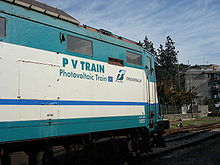
- E636-385 was part of the "PV Train" project and received photovoltaicPhotovoltaicsPhotovoltaics is a method of generating electrical power by converting solar radiation into direct current electricity using semiconductors that exhibit the photovoltaic effect. Photovoltaic power generation employs solar panels composed of a number of solar cells containing a photovoltaic material...
cells used to recharge the 24 V batteries. Due to this, it has been inserted in the asset of Italian historical units; - E636-082 has been used for testing in 1965 of rheostatic braking (the same system was later adopted on FS Class E444FS Class E444The FS E444 is a class of Italian railways electric locomotives. They were introduced in the course of the 1960 until 1975. Starting from 1995, all E444s were upgraded as E444R.The locomotives are nicknamed Tartaruga .-E444 standard:...
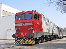
); a second, smaller lever was mounted on the top of the traction lever, and was used to control the braking rheostat. This units also mounted more and bigger vents on its sides. At this time, it has been stripped of many internal components, and is not able to run. - E636-284 is maybe the most famous unit of the group. The unit was involved in an accident, where the driving cabin was damaged. FS decided to recover the unit, and also decided to experiment a new type of driving cabin, similar to the ones used on FS class E656FS Class E656The Class E656 is an Italian articulated rheostatic-type electric locomotive built from 1973 to 1989. An evolution of the E646/5, they are all-purpose locomotives, and have been used on every kind of train, ranging from freight to intercity passenger trasport.The E656 is nicknamed "Caimano" .-...
. The unit is nicknamed "Camilla", originating from which is supposed to be the girlfriend's name of a worker employed in the rebuilding works, who wrote it with chalk near one of the couplers of the locomotive. This unit is also historical. - In 1951 units 044 and 089 received the 92-250 type motors, used on FS Class E424FS Class E424The FS E424 is a class of Italian railways electric locomotives. They were built in 1943-1951 and have been decommissioned in 2008.-History:A design for a small multi-service Bo-Bo locomotive, with speed up to 90 km/h, had been devised by Giuseppe Bianchi as early as in the 1930s, but the...
, and the gear ratio was also changed to 20/65, for a maximum speed allowed of 120 km/h (max power 2,490 kW instead of 2,100 kW). The results of this experiment had proven successful, as these locomotives had the same performances as FS Class E428FS Class E428The FS E428 was a class of Italian railways electric locomotives. They were introduced in the course of the 1930s, for fast services on the Florence-Rome line, being decommissioned in the 1980s.-History:...
(gear ratio 31/101), but with less weight and power; however they were later brought back to their original status. - Units from 271 to 275 where built with different bogies than the standard ones (similar to the ones used on the FS Class E646FS class E646The FS E645 and E646 are two classes of similar electric locomotives used on Italian railways. They were introduced during the 1950s and they have been retired in 2009.- History :...
prototypes), 32RT-200 motors, 5 shunt levels and a gear ratio of 24/74 (max speed 105 km/h). These units were later made identical to standard units.
During the 1960s-1970s Ansaldo-Breda built a locomotive derived from E636 for use in Yugoslavia, classified JŽ 326
HŽ series 1061
The HŽ series 1061 is a 6-axle articulated electric locomotive series still used by Hrvatske Željeznice. It is similar to, and developed from, the Italian FS E636. It was known as JŽ series 362 in SFRJ and currently as SŽ series 362 in Slovenia...
.
See also
- HŽ series 1061HŽ series 1061The HŽ series 1061 is a 6-axle articulated electric locomotive series still used by Hrvatske Željeznice. It is similar to, and developed from, the Italian FS E636. It was known as JŽ series 362 in SFRJ and currently as SŽ series 362 in Slovenia...
- Italian site about E636, with detailed descriptions and photo galleries