

Switched Reluctance Motor
Encyclopedia
Electric motor
An electric motor converts electrical energy into mechanical energy.Most electric motors operate through the interaction of magnetic fields and current-carrying conductors to generate force...
which runs by reluctance
Magnetic reluctance
Magnetic reluctance, or magnetic resistance, is a concept used in the analysis of magnetic circuits. It is analogous to resistance in an electrical circuit, but rather than dissipating magnetic energy it stores magnetic energy...
torque. It has wound field coils as in a DC motor
DC motor
A DC motor is an electric motor that runs on direct current electricity.-Brush:The brushed DC electric motor generates torque directly from DC power supplied to the motor by using internal commutation, stationary magnets , and rotating electrical magnets.Like all electric motors or generators,...
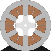
for the stator windings. The rotor however has no magnets or coils attached. The rotor of the motor becomes aligned as soon as the opposite poles of the stator become energised. In order to achieve a full rotation of the motor, the windings must be energised in the correct sequence. For example, if the poles a1 and a2 are energised then the rotor will align itself with these poles. Once this has occurred it is possible for the stator poles to be de-energised before the stator poles of b1 and b2 are energised. The rotor is now positioned at the stator poles b. This sequence continues through c before arriving back at the start. This sequence can also be reversed to achieve motion in the opposite direction. This sequence can be found to be unstable while in operation.
Control
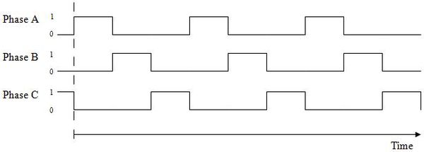
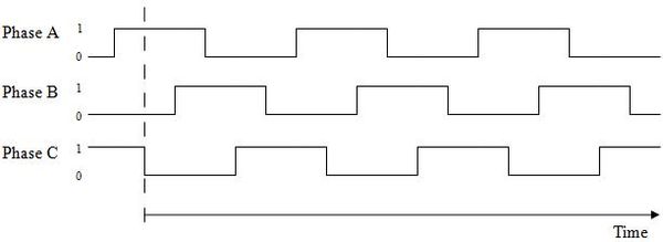
The control system is responsible for giving the required sequential pulses to the power circuitry in order to activate the phases as required. There are two options for producing the sequence including a microcontroller to produce the signal or a timer circuit which could also produce the desired signal.Timer
The use of a timer circuit would be very effective in producing the necessary signal with which to control the circuit. As the required signal is very simple it could easily be implemented by a digital timer, such as the 555 timer. A digital timer is more precise than any other form of timer, such as a mechanical timer. With the widespread use of digital logic within integrated circuits the cost of these timers has reduced considerably. The latest controllers in use incorporate programmable logic controllers (PLC’s) rather than electromechanical components in their implementation. Within PLC’s, the timers are normally simulated by the software incorporated in the controller; the timer is therefore controlled by the software. There are obvious advantages to this system, although the control of a soft start could be hard to implement in this way.Microcontroller
A microcontroller is ideal for this kind of application since it enables a very precise control of the phase activation timings. It also gives the possibility of implementing a soft start function in software form, in order to reduce the amount of hardware required. This is explained in the soft start section of this article.Power circuitry
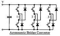
There are 3 phases in an asymmetric bridge converter corresponding to the phases of the switched reluctance motor. If both of the power switches on either side of the phase are turned on, then that corresponding phase shall be actuated. Once the current has risen above the set value, the switch shall turn off. The energy now stored within the motor winding shall now maintain the current in the same direction until that energy is depleted.
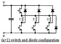
A capacitor can be added to either configuration, and is used to address noise issues by ensuring that the switching of the power switches shall not cause fluctuations in the supply voltage.