Nullor
Encyclopedia
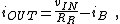
A nullor is a theoretical two-port network
composed of a nullator
at its input and a norator
at its output. Nullors represent an ideal amplifier
, having infinite current, voltage, transconductance and transimpedance gain. Its transmission parameters are all zero, that is, its input-output behavior is summarized with the matrix:
Two-port network
A two-port network is an electrical circuit or device with two pairs of terminals connected together internally by an electrical network...
composed of a nullator
Nullator
In electronics, a nullator is a theoretical linear, time-invariant one-port defined as having zero current and voltage across its terminals. Nullators are strange in the sense that they simultaneously have properties of both a short and an open circuit...
at its input and a norator
Norator
In electronics, a norator is a theoretical linear, time-invariant one-port which can have an arbitrary current and voltage between its terminals...
at its output. Nullors represent an ideal amplifier
Amplifier
Generally, an amplifier or simply amp, is a device for increasing the power of a signal.In popular use, the term usually describes an electronic amplifier, in which the input "signal" is usually a voltage or a current. In audio applications, amplifiers drive the loudspeakers used in PA systems to...
, having infinite current, voltage, transconductance and transimpedance gain. Its transmission parameters are all zero, that is, its input-output behavior is summarized with the matrix:
-

In negative feedbackNegative feedbackNegative feedback occurs when the output of a system acts to oppose changes to the input of the system, with the result that the changes are attenuated. If the overall feedback of the system is negative, then the system will tend to be stable.- Overview :...
circuits, the circuit surrounding the nullor determines the nullor output in such a way as to force the nullor input to zero.
Inserting a nullor in a circuit schematic imposes mathematical constraints on how that circuit must behave, forcing the circuit itself to adopt whatever arrangements are needed to meet the conditions. For example, an ideal op amp can be modeled using a nullor, and the textbook analysis of a feedback circuit using an ideal op amp uses the mathematical conditions imposed by the nullor to analyze the circuit surrounding the op amp.
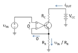
Example: voltage-controlled current sink
Figure 1 shows a voltage-controlled current sink. The sink is intended to draw the same current iOUT regardless of the applied voltage VCC at the output. The value of current drawn is to be set by the input voltage vIN. Here the sink is to be analyzed by idealizing the op amp as a nullor.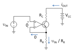
Using properties of the input nullator portion of the nullor, the input voltage across the op amp input terminals is zero. Consequently, the voltage across reference resistor RR is the applied voltage vIN, making the current in RR simply vIN / RR. Again using the nullator properties, the input current to the nullor is zero. Consequently, Kirchhoff's current law at the emitter provides an emitter current of vIN / RR. Using properties of the norator output portion of the nullor, the nullor provides whatever current is demanded of it, regardless of the voltage at its output. In this case, it provides the transistor base current iB. Thus, Kirchhoff's current law applied to the transistor as a whole provides the output current drawn through resistor RC as:
where the base current of the bipolar transistor iB is normally negligible provided the transistor remains in active mode. That is, based upon the idealization of a nullor, the output current is controlled by the user-applied input voltage vIN and the designer's choice for the reference resistor RR.
The purpose of the transistor in the circuit is to reduce the portion of the current in RR supplied by the op amp. Without the transistor, the current through RC would be iOUT = ( VCC − vIN ) / RC, which interferes with the design goal of independence of iOUT from VCC. Another practical advantage of the transistor is that the op amp must deliver only the small transistor base current, which is unlikely to tax the op amp's current delivery capability. Of course, only real op amps are current-limited, not nullors.
The remaining variation of the current with the voltage VCC is due to the Early effectEarly EffectThe Early effect is the variation in the width of the base in a bipolar junction transistor due to a variation in the applied base-to-collector voltage, named after its discoverer James M. Early...
, which causes the β of the transistor to change with its collector-to-base voltage VCB according to the relation β = β0 ( 1 + VCB / VA ), where VA is the so-called Early voltage. Analysis based upon a nullor leads to the output resistance of this current sink as Rout = rO ( β + 1 ) + RC , where rO is the small-signal transistor output resistance given by rO = ( VA + VCB ) / iout. See current mirror for the analysis.
Use of the nullor idealization allows design of the circuitry around the op amp. The practical problem remains of designing an op amp that behaves like a nullor.-