
Isolation amplifier
Encyclopedia
Isolation amplifiers provide electrical isolation and an electrical safety barrier. They protect data acquisition
components from common mode voltages, which are potential differences between instrument ground and signal ground. Instruments without an isolation barrier that are applied in the presence of a common mode voltage allow ground currents to circulate, leading in the best case to a noisy representation of the signal under investigation. In the worst case, assuming that the magnitude of common mode voltage and/or current is sufficient, instrument destruction is likely.
Amplifiers with an isolation barrier allow the front-end of the amplifier to float with respect to common mode voltage to the limit of the barrier's breakdown voltage, which is often 1,000 VDC, peak AC, or more. This action serves to protect the amplifier and the instrument connected to it, while still allowing a reasonably accurate measurement.
These amplifiers are also used for amplifying low-level signals in multi-channel applications. They can also eliminate measurement errors caused by ground loops
. Amplifiers with internal transformer
s reduce circuit costs by eliminating the need for additional isolated power supply
. They are usually used as analogue interfaces between systems with separated grounds
.
There are two types:
In most applications, an output voltage
is obtained by passing the output current
through a resistor
.
Other applications:
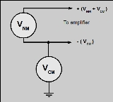
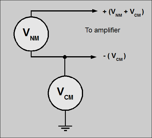 All signal sources are a composite of two major components. The normal mode component (VNM) represents the signal of interest and is the voltage that is applied directly across the inputs of the amplifier. The common mode component (VCM) represents the difference in potential between the low side of the normal mode component and the ground of the amplifier that is used to measure the signal of interest (the normal mode voltage).
In many measurement situations the common mode component is irrelevantly low, but rarely zero. Common mode components of only a few millivolts are frequently encountered and largely and successfully ignored, especially when the normal mode component is orders of magnitude larger.
The first indicator that common mode voltage magnitude is competing with the normal mode component is a noisy reproduction of the latter at the amplifier’s output. Such a situation does not usually define the need for an isolation amplifier, but rather a differential amplifier
. Since the common mode component appears simultaneously and in phase on both amplifier inputs, the differential amplifier, within the limits of the amplifier’s design, can reject it.
However, if the sum of the normal mode and common mode voltages exceeds either the differential amplifier’s common mode range, or maximum range without damage then the need for an isolation amplifier is firmly established.
Furthermore, the frequency of the common mode voltage can adversely affect performance. Higher frequency common mode voltages create difficulty for many isolation amplifiers due to the parasitic capacitance of the isolation barrier. This capacitance appears as a low impedance to higher frequency signals, and allows the common mode voltage to essentially blow past the barrier and interfere with measurements, or even damage the amplifier. However, most common mode voltages are a composite of line voltages, so frequencies generally remain in the 50 to 60 Hz region with some harmonic content, well within the rejection range of most isolation amplifiers.
In other less spectacular failure modes, a differential amplifier will often subtly break in the presence of a common mode voltage that only slightly exceeds its maximum range specification. Novice technicians will often irreparably damage successive differential amplifiers in this manner until the presence of a common mode voltage component is identified, and the differential amplifier is replaced with an isolation amplifier.
Similar to the instrumentation amplifier, Isolation amplifiers have fixed differential gain over a wide range of frequencies, high input impedance and low output impedance.
For most industrial applications that require isolation, the single-ended floating design provides the best price/performance.
There are also two broad classifications of isolation amplifiers that should be considered in tandem with the application:
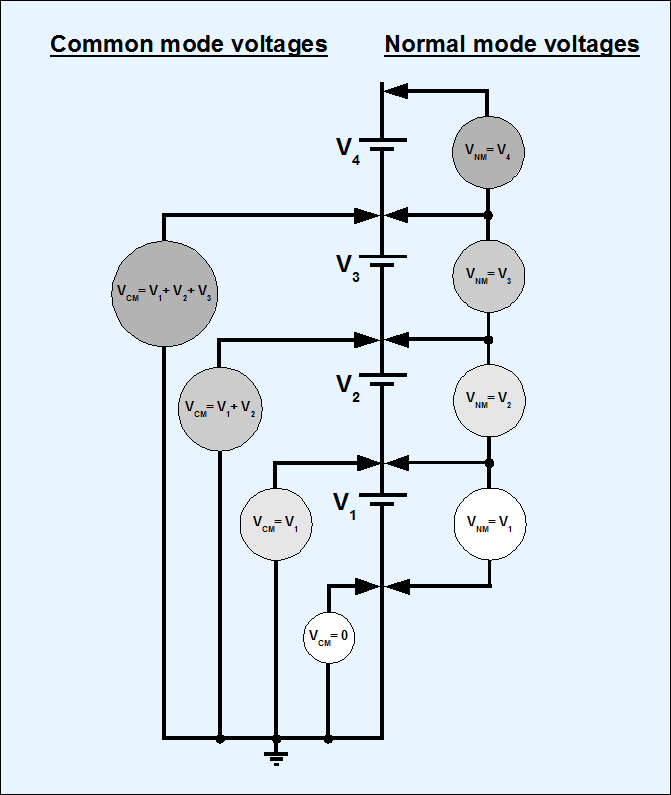 Stacked voltage cell measurements are common with the growing popularity of solar cells and fuel cells. In this application the technician wants to profile the performance of individual series-connected voltages cells, but the need for an isolated amplifier is often overlooked. That requirement is defined by the fact that each voltage cell (the normal mode voltage) is removed from ground by an amount equal to the sum of the voltage cells below it (the common mode voltage). Unless the amplifiers used to measure individual cell voltages are allowed to float at a level equal to the common mode voltage, measurements are not likely to be accurate for any but the first cell in the string where the common mode voltage is zero.
An exception to this premise is allowed for a non-isolated differential amplifier, but only to the point that the common mode voltage does not exceed the amplifier’s common mode range, and especially its maximum measurement range without damage.
Data acquisition
Data acquisition is the process of sampling signals that measure real world physical conditions and converting the resulting samples into digital numeric values that can be manipulated by a computer. Data acquisition systems typically convert analog waveforms into digital values for processing...
components from common mode voltages, which are potential differences between instrument ground and signal ground. Instruments without an isolation barrier that are applied in the presence of a common mode voltage allow ground currents to circulate, leading in the best case to a noisy representation of the signal under investigation. In the worst case, assuming that the magnitude of common mode voltage and/or current is sufficient, instrument destruction is likely.
Amplifiers with an isolation barrier allow the front-end of the amplifier to float with respect to common mode voltage to the limit of the barrier's breakdown voltage, which is often 1,000 VDC, peak AC, or more. This action serves to protect the amplifier and the instrument connected to it, while still allowing a reasonably accurate measurement.
These amplifiers are also used for amplifying low-level signals in multi-channel applications. They can also eliminate measurement errors caused by ground loops
Ground loop (electricity)
In an electrical system, a ground loop usually refers to a current, almost always unwanted, in a conductor connecting two points that are supposed to be at the same potential, often ground, but are actually at different potentials. Ground loops created by improperly designed or improperly installed...
. Amplifiers with internal transformer
Transformer
A transformer is a device that transfers electrical energy from one circuit to another through inductively coupled conductors—the transformer's coils. A varying current in the first or primary winding creates a varying magnetic flux in the transformer's core and thus a varying magnetic field...
s reduce circuit costs by eliminating the need for additional isolated power supply
Power supply
A power supply is a device that supplies electrical energy to one or more electric loads. The term is most commonly applied to devices that convert one form of electrical energy to another, though it may also refer to devices that convert another form of energy to electrical energy...
. They are usually used as analogue interfaces between systems with separated grounds
Ground (electricity)
In electrical engineering, ground or earth may be the reference point in an electrical circuit from which other voltages are measured, or a common return path for electric current, or a direct physical connection to the Earth....
.
There are two types:
- Two ports:
- when the DC-DC is not integrated.
- when there are two isolated parts.
- Three ports:
- When the DC-DC is integrated.
- the parts are isolated between them.
In most applications, an output voltage
Voltage
Voltage, otherwise known as electrical potential difference or electric tension is the difference in electric potential between two points — or the difference in electric potential energy per unit charge between two points...
is obtained by passing the output current
Electric current
Electric current is a flow of electric charge through a medium.This charge is typically carried by moving electrons in a conductor such as wire...
through a resistor
Resistor
A linear resistor is a linear, passive two-terminal electrical component that implements electrical resistance as a circuit element.The current through a resistor is in direct proportion to the voltage across the resistor's terminals. Thus, the ratio of the voltage applied across a resistor's...
.
Other applications:
- Floating pulse amplifier output voltage and current interface.
- InstrumentationInstrumentationInstrumentation is defined as the art and science of measurement and control of process variables within a production, or manufacturing area....
in high-noise environments. - Analogue front-end processing.
- Medical instrumentation.
Signal source components
In many measurement situations the common mode component is irrelevantly low, but rarely zero. Common mode components of only a few millivolts are frequently encountered and largely and successfully ignored, especially when the normal mode component is orders of magnitude larger.
The first indicator that common mode voltage magnitude is competing with the normal mode component is a noisy reproduction of the latter at the amplifier’s output. Such a situation does not usually define the need for an isolation amplifier, but rather a differential amplifier
Differential amplifier
A differential amplifier is a type of electronic amplifier that amplifies the difference between two voltages but does not amplify the particular voltages.- Theory :Many electronic devices use differential amplifiers internally....
. Since the common mode component appears simultaneously and in phase on both amplifier inputs, the differential amplifier, within the limits of the amplifier’s design, can reject it.
However, if the sum of the normal mode and common mode voltages exceeds either the differential amplifier’s common mode range, or maximum range without damage then the need for an isolation amplifier is firmly established.
Isolation amplifier usage
Isolation amplifiers exist only to make the common mode component of a signal source largely irrelevant to normal mode component measurement. The capacity of an isolation amplifier to fulfill this ideal is a function of two key isolation amplifier specifications:- The amplifier’s isolation breakdown voltage, which defines the absolute maximum common mode voltage that it will tolerate without damage. Specifications of 1,000 volts and more are common.
- The amplifier’s common mode rejection ratio (often abbreviated CMRR). The CMRR specification defines the degree to which the common mode voltage will disrupt the normal mode component measurement, and therefore affect measurement accuracy.
Furthermore, the frequency of the common mode voltage can adversely affect performance. Higher frequency common mode voltages create difficulty for many isolation amplifiers due to the parasitic capacitance of the isolation barrier. This capacitance appears as a low impedance to higher frequency signals, and allows the common mode voltage to essentially blow past the barrier and interfere with measurements, or even damage the amplifier. However, most common mode voltages are a composite of line voltages, so frequencies generally remain in the 50 to 60 Hz region with some harmonic content, well within the rejection range of most isolation amplifiers.
Misconceptions
Isolation amplifiers are commonly confused with differential amplifiers. The misconception is that differential and isolation amplifiers are synonymous. This false impression has often caused the incineration of differential amplifiers in large common mode applications where an isolation amplifier was in order.In other less spectacular failure modes, a differential amplifier will often subtly break in the presence of a common mode voltage that only slightly exceeds its maximum range specification. Novice technicians will often irreparably damage successive differential amplifiers in this manner until the presence of a common mode voltage component is identified, and the differential amplifier is replaced with an isolation amplifier.
Similar to the instrumentation amplifier, Isolation amplifiers have fixed differential gain over a wide range of frequencies, high input impedance and low output impedance.
Amplifier selection guidelines
Instrumentation amplifiers can be classified into four broad categories, organized from least to most costly:- Single-ended. An unbalanced input, non-isolated. Suitable for measurements where common mode voltages are zero, or extremely small. Very inexpensive.
- Differential. A balanced input, non-isolated. Suitable for measurements where the sum of common mode and normal mode voltages remains within the measurement range of the amplifier.
- Single-ended, floating common. An isolated and quasi-balanced input (the floating common is typically connected to the (-) input of a differential amplifier). Suitable for off-ground measurements up to the breakdown voltage of the isolation barrier, and exhibits very good common mode rejection (100 db typical).
- Differential, floating common. An, isolated and balanced input. Suitable for off-ground measurements to the breakdown voltage of the isolation barrier, and exhibits superb common mode rejection (>120 db).
For most industrial applications that require isolation, the single-ended floating design provides the best price/performance.
There are also two broad classifications of isolation amplifiers that should be considered in tandem with the application:
- Amplifiers providing input-to-output isolation without channel-to-channel isolation. This is a less expensive form of isolation that offers only one isolation barrier for a multi-channel instrument. Although the commons of each channel are isolated from power ground by the input-to-output isolation barrier, they are not isolated from each other. Therefore a common mode voltage on one will attempt to float all the others, sometimes with disastrous results. This form of isolation is suitable only when it is certain that that there is only one common mode voltage that is equally applied to all channels.
- Amplifiers providing both input-to-output and channel-to-channel isolation. This is the purest form of isolation, and the option that should be considered for nearly all applications. Multi-channel instruments that employ it are immune to inconsistent common mode voltages on any combination of channels within the limits of the amplifiers.
Stacked voltage cell measurements
An exception to this premise is allowed for a non-isolated differential amplifier, but only to the point that the common mode voltage does not exceed the amplifier’s common mode range, and especially its maximum measurement range without damage.