

EIA-485
Encyclopedia
| RS-485 | |
|---|---|
| Standard | EIA RS-485 |
| Physical Media | Twisted pair Twisted pair Twisted pair cabling is a type of wiring in which two conductors are twisted together for the purposes of canceling out electromagnetic interference from external sources; for instance, electromagnetic radiation from unshielded twisted pair cables, and crosstalk between neighboring pairs... |
| Network Topology Network topology Network topology is the layout pattern of interconnections of the various elements of a computer or biological network.... |
Point-to-point, Multi-dropped Multidrop bus A multidrop bus is a computer bus in which all components are connected to the same set of electrical wires. A process of arbitration determines which device gets the right to be the sender of information at any point in time... , Multi-point Bus network A bus network topology is a network architecture in which a set of clients are connected via a shared communications line, called a bus. There are several common instances of the bus architecture, including one in the motherboard of most computers, and those in some versions of Ethernet... |
| Maximum Devices | 32 drivers or receivers |
| Maximum Distance | 1200 metres (4000 feet) |
| Mode of Operation | Differential signaling Differential signaling Differential signaling is a method of transmitting information electrically by means of two complementary signals sent on two separate wires. The technique can be used for both analog signaling, as in some audio systems, and digital signaling, as in RS-422, RS-485, Ethernet , PCI Express and USB... |
| Maximum Baud Rate | 100 kbit/s - 10 Mbit/s |
| Voltage Levels | -7 V to +12 V |
| Mark(1) | Positive Voltages (B-A > +200 mV) |
| Space(0) | negative voltages (B-A < -200 mV) |
| Available Signals | Tx+/Rx+, Tx-/Rx- (Half Duplex) Tx+, Tx-, Rx+, Rx- (Full Duplex) |
| Connector types | Not specified. |
EIA-485, also known as TIA/EIA-485 or RS-485, is a standard defining the electrical characteristics of drivers and receivers for use in balanced digital multipoint systems. The standard is published by the ANSI
American National Standards Institute
The American National Standards Institute is a private non-profit organization that oversees the development of voluntary consensus standards for products, services, processes, systems, and personnel in the United States. The organization also coordinates U.S. standards with international...
Telecommunications Industry Association
Telecommunications Industry Association
The Telecommunications Industry Association is accredited by the American National Standards Institute to develop voluntary, consensus-based industry standards for a wide variety of ICT products, and currently represents nearly 400 companies...
/Electronic Industries Alliance
Electronic Industries Alliance
The Electronic Industries Alliance was a standards and trade organization composed as an alliance of trade associations for electronics manufacturers in the United States. They developed standards to ensure the equipment of different manufacturers was compatible and interchangeable...
(TIA/EIA). Digital communications networks implementing the EIA-485 standard can be used effectively over long distances and in electrically noisy environments. Multiple receivers may be connected to such a network in a linear, multi-drop configuration. These characteristics make such networks useful in industrial environments and similar applications.
Overview
EIA-485 only specifies electrical characteristics of the driver and the receiver. It does not specify or recommend any communications protocolCommunications protocol
A communications protocol is a system of digital message formats and rules for exchanging those messages in or between computing systems and in telecommunications...
. EIA-485 enables the configuration of inexpensive local networks and multidrop communications links. It offers data transmission
Data transmission
Data transmission, digital transmission, or digital communications is the physical transfer of data over a point-to-point or point-to-multipoint communication channel. Examples of such channels are copper wires, optical fibres, wireless communication channels, and storage media...
speeds of 35 Mbit/s
Bitrate
In telecommunications and computing, bit rate is the number of bits that are conveyed or processed per unit of time....
up to 10 m and 100 kbit/s
Bitrate
In telecommunications and computing, bit rate is the number of bits that are conveyed or processed per unit of time....
at 1200 m. Since it uses a differential balanced line
Balanced line
In telecommunications and professional audio, a balanced line or balanced signal pair is a transmission line consisting of two conductors of the same type, each of which have equal impedances along their lengths and equal impedances to ground and to other circuits. The chief advantage of the...
over twisted pair
Twisted pair
Twisted pair cabling is a type of wiring in which two conductors are twisted together for the purposes of canceling out electromagnetic interference from external sources; for instance, electromagnetic radiation from unshielded twisted pair cables, and crosstalk between neighboring pairs...
(like EIA-422
EIA-422
RS-422 is a technical standard that specifies electrical characteristics of a digital signalling circuit. Differential-mode signals can be sent at rates as high as 10 million bits per second, or may be sent on cables as long as 1200 metres. Some systems directly interconnect using RS 422 signals,...
), it can span relatively large distances (up to 4000 feet (1,219.2 m)). A rule of thumb is that the speed in bit/s multiplied by the length in meters should not exceed 108. Thus a cable should not signal faster than .
In contrast to EIA-422
EIA-422
RS-422 is a technical standard that specifies electrical characteristics of a digital signalling circuit. Differential-mode signals can be sent at rates as high as 10 million bits per second, or may be sent on cables as long as 1200 metres. Some systems directly interconnect using RS 422 signals,...
, which has a single driver circuit which cannot be switched off, EIA-485 drivers need to be put in transmit mode explicitly by asserting a signal to the driver. This allows EIA-485 to implement linear topologies
Network topology
Network topology is the layout pattern of interconnections of the various elements of a computer or biological network....
using only two wires. The equipment located along a set of EIA-485 wires are interchangeably called nodes, stations and devices.
The recommended arrangement of the wires is as a connected series of point-to-point (multidropped) nodes, a line or bus, not a star, ring, or multiply connected network. Ideally, the two ends of the cable will have a termination resistor connected across the two wires. Without termination resistors, reflections of fast driver edges can cause multiple data edges that can cause data corruption. Termination resistors also reduce electrical noise sensitivity due to the lower impedance, and bias resistors (see below) are required. The value of each termination resistor should be equal to the cable impedance (typically, 120 ohms for twisted pairs).
Star and ring topologies are not recommended because of signal reflections or excessively low or high termination impedance. But if a star configuration is unavoidable, such as when controlling multiple pan tilt zoom cameras from a central video surveillance hub, special EIA-485 star/hub repeaters are available which bidirectionally listen for data on each span and then retransmit the data onto all other spans.
Somewhere along the set of wires, pull up or pull down resistors are established to Fail-safe
Fail-safe
A fail-safe or fail-secure device is one that, in the event of failure, responds in a way that will cause no harm, or at least a minimum of harm, to other devices or danger to personnel....
bias each data line/wire when the lines are not being driven by any device. This way, the lines will be biased to known voltages and nodes will not interpret the noise from undriven lines as actual data; without biasing resistors, the data lines float in such a way that electrical noise sensitivity is greatest when all device stations are silent or unpowered.
Master-slave arrangement
Often in a master-slave arrangement when one device dubbed "the master" initiates all communication activity, the master device itself provides the bias and not the slave devices. In this configuration, the master device is typically centrally located along the set of EIA-485 wires, so it would be two slave devices located at the physical end of the wires that would provide the terminationElectrical termination
Electrical termination of a signal involves providing a terminator at the end of a wire or cable to prevent an RF signal from being reflected back from the end, causing interference...
. The master device itself would provide termination if it were located at a physical end of the wires, but that is often a bad design as the master would be better located at a halfway point between the slave devices. Note that it is not a good idea to apply the bias at multiple node locations, because, by doing so, the effective bias resistance is lowered, which could possibly cause a violation of the EIA-485 specification and cause communications to malfunction. By keeping the biasing with the master, slave device design is simplified and this situation is avoided.
Three-wire connection
Full duplex operation
EIA-485, like EIA-422 can be made full-duplexDuplex (telecommunications)
A duplex communication system is a system composed of two connected parties or devices that can communicate with one another in both directions. The term multiplexing is used when describing communication between more than two parties or devices....
by using four wires. Since EIA-485 is a multi-point specification, however, this is not necessary in many cases. EIA-485 and EIA-422 can interoperate with certain restrictions.
Converters between EIA-485 and other formats are available to allow a personal computer
Personal computer
A personal computer is any general-purpose computer whose size, capabilities, and original sales price make it useful for individuals, and which is intended to be operated directly by an end-user with no intervening computer operator...
to communicate with remote devices. By using "Repeaters" and "Multi-Repeaters" very large RS-485 networks can be formed. The Application Guidelines for TIA/EIA-485-A has one diagram called "Star Configuration. Not recommended." Using an RS-485 "Multi-Repeater" can allow for "Star Configurations" with "Home Runs" (or multi-drop) connections similar to Ethernet Hub/Star implementations (with greater distances). Hub/Star systems (with "Multi-Repeaters") allow for very maintainable systems, without violating any of the RS-485 specifications. Repeaters can also be used to extend the distance or number of nodes on a network.
Applications
EIA-485 signals are used in a wide range of computer and automation systems. In a computer system, SCSISCSI
Small Computer System Interface is a set of standards for physically connecting and transferring data between computers and peripheral devices. The SCSI standards define commands, protocols, and electrical and optical interfaces. SCSI is most commonly used for hard disks and tape drives, but it...
-2 and SCSI-3 may use this specification to implement the physical layer
Physical layer
The physical layer or layer 1 is the first and lowest layer in the seven-layer OSI model of computer networking. The implementation of this layer is often termed PHY....
for data transmission between a controller and a disk drive. EIA-485 is used for low-speed data communications in commercial aircraft cabins vehicle bus
Vehicle bus
A vehicle bus is a specialized internal communications network that interconnects components inside a vehicle...
. It requires minimal wiring, and can share the wiring among several seats, reducing weight.
EIA-485 is used as the physical layer underlying many standard and proprietary automation protocols used to implement Industrial Control Systems
Industrial Control Systems
Industrial control system is a general term that encompasses several types of control systems used in industrial production, including supervisory control and data acquisition systems, distributed control systems , and other smaller control system configurations such as skid-mounted programmable...
, including the most common versions of Modbus
Modbus
Modbus is a serial communications protocol published by Modicon in 1979 for use with its programmable logic controllers . Simple and robust, it has since become one of the de facto standard communications protocols in the industry, and it is now amongst the most commonly available means of...
and Profibus
Profibus
PROFIBUS is a standard for field bus communication in automation technology and was first promoted in 1989 by BMBF...
. These are used in programmable logic controller
Programmable logic controller
A programmable logic controller or programmable controller is a digital computer used for automation of electromechanical processes, such as control of machinery on factory assembly lines, amusement rides, or light fixtures. PLCs are used in many industries and machines...
s and on factory floors. Since it is differential, it resists electromagnetic interference from motors and welding equipment.
In theatre and performance venues EIA-485 networks are used to control lighting and other systems using the DMX512 protocol.
In surveillance
Surveillance
Surveillance is the monitoring of the behavior, activities, or other changing information, usually of people. It is sometimes done in a surreptitious manner...
, EIA-485 is used to control pan tilt zoom cameras.
EIA-485 is also used in building automation
Building automation
Building automation describes the functionality provided by the control system of a building. A building automation system is an example of a distributed control system...
as the simple bus wiring and long cable length is ideal for joining remote devices. It may be used to control video surveillance systems or to interconnect security control panels and devices such as access control card readers.
Although many applications use EIA-485 signal levels, the speed, format, and protocol of the data transmission is not specified by EIA-485. Interoperation even of similar devices from different manufacturers is not assured by compliance with the signal levels alone.
Connectors
EIA-485 does not specify any connector or pinout. Circuits may be terminated on screw terminalScrew terminal
A screw terminal is a type of electrical connector where a wire is clamped down to metal by a screw.The wire is sometimes just stripped of electrical insulation at the end, and is bent in a U or J shape to fit around the shaft of the screw....
s, D-subminiature
D-subminiature
The D-subminiature or D-sub is a common type of electrical connector. They are named for their characteristic D-shaped metal shield. When they were introduced, D-subs were among the smaller connectors used on computer systems....
connectors, or other types of connectors.
Signs of common mistakes
From a software engineer's perspective, miswired RS-485 can lead to spurious characters because a spurious mark bit is seen. A bus without good pull up and pull down resistors will be noise-sensitive. These can be system-wide (albeit trivial) problems that require looking beyond just the CPU that is being programmed.Pin labeling
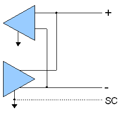
The EIA-485 differential line consists of two pins:- A aka '−' aka TxD-/RxD- aka inverting pin
- B aka '+' aka TxD+/RxD+ aka non-inverting pin
- SC aka G aka reference pin.
The SC line is the optional voltage reference connection. This is the reference potential used by the transceiver to measure the A and B voltages.
The B line is positive (compared to A) when the line is idle (i.e., data is 1).
In addition to the A and B connections, the EIA standard also specifies a third interconnection point called C, which is the common signal reference ground.
These names are all in use on various equipment, but the actual standard released by EIA only uses the names A and B. However, despite the unambiguous standard, there is much confusion about which is which:
The EIA-485 signaling specification states that signal A is the inverting or '-' pin and signal B is the non-inverting or '+' pin.
This is in conflict with the A/B naming used by a number of differential transceiver manufacturers, including, among others:
- Texas Instruments, as seen in their application handbook on EIA-422/485 communications (A=non-inverting, B=inverting)
- Intersil, as seen in their data sheet for the ISL4489 transceiver
- Maxim, as seen in their data sheet for the MAX483 transceiver
These manufacturers are incorrect, but their practice is in widespread use.
Therefore, care must be taken when using A/B naming.
The standard does not discuss cable shielding, but makes some recommendations on preferred methods of interconnecting the signal reference common and equipment case grounds.
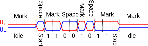
Waveform example
The graphChart
A chart is a graphical representation of data, in which "the data is represented by symbols, such as bars in a bar chart, lines in a line chart, or slices in a pie chart"...
below shows potentials
Electric potential
In classical electromagnetism, the electric potential at a point within a defined space is equal to the electric potential energy at that location divided by the charge there...
of the '+' and '−' pins of an EIA-485 line during transmission
Data transmission
Data transmission, digital transmission, or digital communications is the physical transfer of data over a point-to-point or point-to-multipoint communication channel. Examples of such channels are copper wires, optical fibres, wireless communication channels, and storage media...
of one byte
Byte
The byte is a unit of digital information in computing and telecommunications that most commonly consists of eight bits. Historically, a byte was the number of bits used to encode a single character of text in a computer and for this reason it is the basic addressable element in many computer...
(0xD3, least significant bit
Least significant bit
In computing, the least significant bit is the bit position in a binary integer giving the units value, that is, determining whether the number is even or odd. The lsb is sometimes referred to as the right-most bit, due to the convention in positional notation of writing less significant digits...
first) of data using an asynchronous start-stop
Asynchronous start-stop
Asynchronous serial communication describes an asynchronous, serial transmission protocol in which a start signal is sent prior to each byte, character or code word and a stop signal is sent after each code word...
method.
See also
- Electronic Industries AllianceElectronic Industries AllianceThe Electronic Industries Alliance was a standards and trade organization composed as an alliance of trade associations for electronics manufacturers in the United States. They developed standards to ensure the equipment of different manufacturers was compatible and interchangeable...
- RS-232RS-232In telecommunications, RS-232 is the traditional name for a series of standards for serial binary single-ended data and control signals connecting between a DTE and a DCE . It is commonly used in computer serial ports...
- RS-422
- RS-423RS-423RS/EIA/TIA-423 is a standard for serial communications. It defines an unbalanced interface , with a single, unidirectional sending driver, and allows for up to 10 receivers . It is normally implemented in integrated circuit technology and can also be employed for the interchange of serial binary...
- ProfibusProfibusPROFIBUS is a standard for field bus communication in automation technology and was first promoted in 1989 by BMBF...
- FieldbusFieldbusFieldbus is the name of a family of industrial computer network protocols used for real-time distributed control, now standardized as IEC 61158....
- List of network buses