
Charlieplexing
Encyclopedia
Charlieplexing is a technique proposed in early 1995 by Charlie Allen at Maxim Integrated Products
for driving a multiplexed display
in which relatively few I/O pins on a microcontroller
are used to drive an array of LEDs. The method utilizes the tri-state logic capabilities of microcontrollers in order to gain efficiency over traditional multiplexing. Although it is more efficient in its use of I/O, there are issues that cause it to be more complicated to design and render it impractical for larger displays. These issues include duty cycle, current requirements and the forward voltages of the LEDs.
When using charlieplexing, n drive pins can drive n digits with n-1 segments. When simplified, it equates to n pins being able to drive n2-n segments or LEDs. Traditional multiplexing takes many more pins to drive the same number of LEDs; 2n pins must be used to drive n2 LEDs (though a 1-of-n decoder chip can be used to reduce the number of microcontroller I/O pins to ).
).
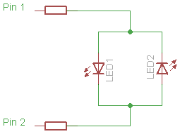
By applying a positive charge to pin 1 and grounding pin 2, LED 1 will light. Since current cannot flow through LEDs in reverse bias, LED 2 will remain unlit. If the charges on pin 1 and pin 2 are reversed, LED 2 will light and LED 1 will be unlit.
The Charlieplexing technique does not actually make a larger matrix possible when only using two pins, because two LEDs can be driven by two pins without any matrix connections, and without even using tri-state mode. However, the 2-pin circuit serves as a simple example to show the basic concepts before moving on to larger circuits where Charlieplexing actually shows an advantage.
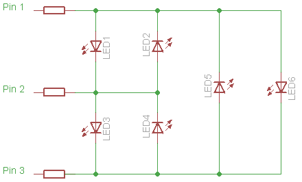
This presents a problem however. In order for this circuit to act like the previous one, we must disconnect one of the pins before applying charge to the remaining two. This can be solved by utilizing the tri-state logic properties of microcontroller pins. Microcontroller pins generally have three states, 5 V, 0 V and input. Input mode puts the pin into a high impedance
state which, electrically speaking, “disconnects” that pin from the circuit, meaning little or no current will flow through it. This allows for the circuit to see any number of pins connected at any time, simply by changing the state of the pin. In order to drive the 6 LED matrix above, the two pins corresponding to the LED we wish to light are connected to 5 V and 0 V while the third pin is set in its input state. In doing so, we prevent current leakage out of the third pin, ensuring that the LED we wish to light is the only one lit.
By using tri-state logic, the matrix can theoretically be expanded to any size, as long as pins are available. For n pins, you can have up to n(n-1) LEDs in the matrix. Any LED can be lit by applying 5 V and 0 V to its corresponding pins and setting all of the other pins connected to the matrix to input mode.
for each LED must be greater than 50 Hz. Suppose 8 tri-state pins are used to control 56 LEDs via charlieplexing, which is enough for 8 7-segment displays (without decimal points). Typically 7-segment displays are made to have a common cathode, sometimes a common anode, but without loss of generality suppose it is a common cathode. All LEDs in all 8 7-segment displays cannot be turned on simultaneously in any desired combination via charlieplexing. It is impossible to get 56 bits of information directly from 8 trits (the term for a base-3 character, as the pins are 3-state) of information, as 8 trits fundamentally comprises 8*log(3)/log(2) or about 12.7 bits of information, which falls far short of the 56 bits required to turn all 56 LEDs on or off in any arbitrary combination. Instead, the human eye must be fooled by use of a flicker. Only one 7-segment display, one set of 7 LEDs can be active at any time. The way this would be done is for the 8 common cathodes of the 8 displays to each get assigned to its own unique pin among the 8 I/O ports. At any time, one and only one of the 8 controlling I/O pins will be actively low, and thus only the 7-segment display with its common cathode connected to that actively low pin can have any of its LEDs on. That is the active 7-segment display. The anodes of the 7 LED segments within the active 7-segment display can then be turned on in any combination by having the other 7 I/O ports either high or in high-impedance mode, in any combination. They are connected to the remaining 7 pins, but through resistors (the common cathode connection is connected to the pin itself, not through a resistor, because otherwise the current through each individual segment would depend on the number of total segments turned on, as they'd all have to share a single resistor). But to show a desired number using all 8 digits, only one 7-segment display can be shown at a time, so all 8 must be cycled through separately, and in a 50th of a second for the entire period of 8. Thus the display must be refreshed at 400 Hz for the period-8 cycle through all 8 segments to make the LEDs flash no slower than 50 times per second. This requires constant interruption of whatever additional processing the controller performs, 400 times per second.
, the current
requirement of a charlieplexed display increases much faster than it would with a traditionally multiplexed display. As the display gets larger, the average current flowing through the LED must be (roughly) constant in order for it to maintain constant brightness, thus requiring the peak current to increase proportionally. This causes a number of issues that limit the practical size of a charlieplexed display.
s, like when using different color LEDs, problems can exist where other LEDs will light when not wanted to.
If we look at the diagram above we notice that if LED 6 has a four volt forward voltage, and LED’s 1 and 3 have forward voltages of two volts or less, they will light when LED 6 is intended to, as their current path is shorter. This issue can easily be avoided by checking the forward voltages of the LEDs used in the matrix and checking for compatibility issues. Or, more simply, using LEDs that have the same forward voltage.
If the failed LED becomes an open circuit, the voltage between the LEDs 2 electrodes may build up until it finds a path through two LEDs. There are as many such paths as there are pins used to control the array minus 2; if the LED with anode at node m and cathode at node n fails in this way, it may be that every single pair of LEDs in which one's anode is node m, cathode is p for any value of p (with the exceptions that p cannot be m or n, so there are as many possible choices for p as the number of pins controlling the array minus 2), along with the LED whose anode is p and cathode is n, will all light up.
If there are 8 I/O pins controlling the array, this means there will be 6 parasitic paths through pairs of 2 LEDs, and 12 LEDs may be unintentionally lit, but fortunately this will only happen when the one bad LED is supposed to come on, which may be a small fraction of the time, and will exhibit no deleterious symptoms when the problem LED is not supposed to be lit. If the problem is a short between nodes x and y, then every time any LED U with either x or y as its anode or cathode and some node z as its other electrode is supposed to come on (without loss of generality, suppose U's cathode is connected to x), the LED V with cathode y and anode z will light as well, so any time EITHER node x or y is activated as an anode OR a cathode, two LEDs will come on instead of one. In this case, it lights only one additional LED unintentionally, but it does it far more frequently; not merely when the failed LED is supposed to come on, but when ANY LED which has a pin in common with the failed LED is supposed to come on.
The problem elements become especially difficult to identify if there are two or more LEDs at fault. What this means is that unlike most methods in which the loss of a single LED merely causes a single burned-out segment, when charlieplexing is used, one or two burned-out LEDs, whatever the mode of failure, will almost certainly cause a catastrophic cascade of unintended lightings of the LEDs that still work, very likely rendering the entire device completely and immediately unusable. This must be taken into account when considering the required lifetime and failure characteristics of the device being designed.
One potential application for this is to read a standard (4x3) 12-key numeric keypad using only 4 I/O lines. The traditional row-column scan method requires 4 + 3 = 7 I/O lines. Thus charlieplexing saves 3 I/O lines; however it adds the expense of 12 diodes, (since the diodes are only free when LEDs are used). This reference shows a variation on the circuit that only needs 4 diodes, however that method qualifies as lossy compression, because when certain combinations of buttons are pressed simultaneously, those signals interfere with the microcontroller's ability to read certain other buttons. The microcontroller can always detect when the data is corrupt, but there is no guarantee it can sense the original key presses, unless only one button is pressed at a time. (However, it is probably possible to arrange the circuit so that if at most any two adjacent buttons are pressed, then no data loss will occur.) Basically though, the input is only loss-less on the 4 diode circuit if only one button is pressed at a time, or if certain problematic multiple key presses are avoided. In the 12 diode circuit, this is not an issue, and there is always a one-to-one correspondence between button presses and input data. However, there are so many diodes that are required to use the method (especially for larger arrays) that there is generally no cost savings over the traditional row-column scan method, unless for some reason the cost of a diode is only a fraction of the cost of an I/O pin, where that fraction is one over the number of I/O lines.
Maxim Integrated Products
Maxim Integrated Products is a publicly traded company that designs, manufactures, and sells analog and mixed-signal semiconductor products. Maxim develops integrated circuits for the industrial, communications, consumer, and computing markets....
for driving a multiplexed display
Multiplexed display
Multiplexed displays are electronic displays where the entire display is not driven at one time. Instead, sub-units of the display are multiplexed, that is, driven one at a time, but the electronics and the persistence of vision...
in which relatively few I/O pins on a microcontroller
Microcontroller
A microcontroller is a small computer on a single integrated circuit containing a processor core, memory, and programmable input/output peripherals. Program memory in the form of NOR flash or OTP ROM is also often included on chip, as well as a typically small amount of RAM...
are used to drive an array of LEDs. The method utilizes the tri-state logic capabilities of microcontrollers in order to gain efficiency over traditional multiplexing. Although it is more efficient in its use of I/O, there are issues that cause it to be more complicated to design and render it impractical for larger displays. These issues include duty cycle, current requirements and the forward voltages of the LEDs.
Traditional multiplexing
Display multiplexing is very different from multiplexing used in data transmission, although it has the same basic principles. In display multiplexing, the data lines of the displays are connected together in parallel to a common bus on the microcontroller. Then, the displays are turned on and addressed individually. This allows one to use fewer I/O pins than it would normally take to drive the same number of displays directly.When using charlieplexing, n drive pins can drive n digits with n-1 segments. When simplified, it equates to n pins being able to drive n2-n segments or LEDs. Traditional multiplexing takes many more pins to drive the same number of LEDs; 2n pins must be used to drive n2 LEDs (though a 1-of-n decoder chip can be used to reduce the number of microcontroller I/O pins to
).Complementary drive
Charlieplexing, in its simplest form, works using a matrix of complementary pairs of LEDs. The simplest possible charlieplexed matrix would look like this:By applying a positive charge to pin 1 and grounding pin 2, LED 1 will light. Since current cannot flow through LEDs in reverse bias, LED 2 will remain unlit. If the charges on pin 1 and pin 2 are reversed, LED 2 will light and LED 1 will be unlit.
The Charlieplexing technique does not actually make a larger matrix possible when only using two pins, because two LEDs can be driven by two pins without any matrix connections, and without even using tri-state mode. However, the 2-pin circuit serves as a simple example to show the basic concepts before moving on to larger circuits where Charlieplexing actually shows an advantage.
Expanding: tri-state logic
If we were to expand this circuit to accommodate 3 pins and 6 LEDs, it would look like this:This presents a problem however. In order for this circuit to act like the previous one, we must disconnect one of the pins before applying charge to the remaining two. This can be solved by utilizing the tri-state logic properties of microcontroller pins. Microcontroller pins generally have three states, 5 V, 0 V and input. Input mode puts the pin into a high impedance
High impedance
In electronics, high impedance means that a point in a circuit has a relatively high impedance to other points in the circuit.-Digital electronics:...
state which, electrically speaking, “disconnects” that pin from the circuit, meaning little or no current will flow through it. This allows for the circuit to see any number of pins connected at any time, simply by changing the state of the pin. In order to drive the 6 LED matrix above, the two pins corresponding to the LED we wish to light are connected to 5 V and 0 V while the third pin is set in its input state. In doing so, we prevent current leakage out of the third pin, ensuring that the LED we wish to light is the only one lit.
By using tri-state logic, the matrix can theoretically be expanded to any size, as long as pins are available. For n pins, you can have up to n(n-1) LEDs in the matrix. Any LED can be lit by applying 5 V and 0 V to its corresponding pins and setting all of the other pins connected to the matrix to input mode.
Refresh rate
Because only a single set of LEDs, all having a common anode or cathode, can be lit simultaneously without turning on unintended LEDs, charlieplexing requires frequent output changes, through a method known as flickering. When flickering is done, not all LEDs are lit quite simultaneously, but rather one set of LEDs is lit briefly, then another set, then another, and eventually the cycle repeats. If it is done fast enough, they will appear to all be on, all the time, to the human eye. In order for a display to not have any noticeable flicker, the refresh rateRefresh rate
The refresh rate is the number of times in a second that a display hardware draws the data...
for each LED must be greater than 50 Hz. Suppose 8 tri-state pins are used to control 56 LEDs via charlieplexing, which is enough for 8 7-segment displays (without decimal points). Typically 7-segment displays are made to have a common cathode, sometimes a common anode, but without loss of generality suppose it is a common cathode. All LEDs in all 8 7-segment displays cannot be turned on simultaneously in any desired combination via charlieplexing. It is impossible to get 56 bits of information directly from 8 trits (the term for a base-3 character, as the pins are 3-state) of information, as 8 trits fundamentally comprises 8*log(3)/log(2) or about 12.7 bits of information, which falls far short of the 56 bits required to turn all 56 LEDs on or off in any arbitrary combination. Instead, the human eye must be fooled by use of a flicker. Only one 7-segment display, one set of 7 LEDs can be active at any time. The way this would be done is for the 8 common cathodes of the 8 displays to each get assigned to its own unique pin among the 8 I/O ports. At any time, one and only one of the 8 controlling I/O pins will be actively low, and thus only the 7-segment display with its common cathode connected to that actively low pin can have any of its LEDs on. That is the active 7-segment display. The anodes of the 7 LED segments within the active 7-segment display can then be turned on in any combination by having the other 7 I/O ports either high or in high-impedance mode, in any combination. They are connected to the remaining 7 pins, but through resistors (the common cathode connection is connected to the pin itself, not through a resistor, because otherwise the current through each individual segment would depend on the number of total segments turned on, as they'd all have to share a single resistor). But to show a desired number using all 8 digits, only one 7-segment display can be shown at a time, so all 8 must be cycled through separately, and in a 50th of a second for the entire period of 8. Thus the display must be refreshed at 400 Hz for the period-8 cycle through all 8 segments to make the LEDs flash no slower than 50 times per second. This requires constant interruption of whatever additional processing the controller performs, 400 times per second.
Peak current
Due to the decreased duty cycleDuty cycle
In engineering, the duty cycle of a machine or system is the time that it spends in an active state as a fraction of the total time under consideration....
, the current
Electric current
Electric current is a flow of electric charge through a medium.This charge is typically carried by moving electrons in a conductor such as wire...
requirement of a charlieplexed display increases much faster than it would with a traditionally multiplexed display. As the display gets larger, the average current flowing through the LED must be (roughly) constant in order for it to maintain constant brightness, thus requiring the peak current to increase proportionally. This causes a number of issues that limit the practical size of a charlieplexed display.
- LEDs often have a maximum peak current rating as well as an average current rating.
- If the microcontroller code crashes, the LED left lit is under much higher stress than in a traditionally multiplexed display increasing the risk of a failure before the fault is spotted.
Requirement for tristate
All the outputs used to drive a charlieplexed display must be tristate. If the current is low enough to drive the displays directly off the I/O pins of the microcontroller this is no problem but if external tristates must be used then each tristate will generally require two output lines to control eliminating most of the advantage of a charlieplexed display. Since the current from microcontroller pins is typically limited to 20 mA or so this severely restricts the practical size of a charlieplexed display. However, it can be done enabling one segment at the time.Complexity
Charlieplex matrixes are significantly more complicated, both in the required PC Board layout and microcontroller programming, than are traditional multiplex matrices. This increases design time.Forward voltage
When using LEDs with different forward voltageVoltage
Voltage, otherwise known as electrical potential difference or electric tension is the difference in electric potential between two points — or the difference in electric potential energy per unit charge between two points...
s, like when using different color LEDs, problems can exist where other LEDs will light when not wanted to.
If we look at the diagram above we notice that if LED 6 has a four volt forward voltage, and LED’s 1 and 3 have forward voltages of two volts or less, they will light when LED 6 is intended to, as their current path is shorter. This issue can easily be avoided by checking the forward voltages of the LEDs used in the matrix and checking for compatibility issues. Or, more simply, using LEDs that have the same forward voltage.
LED failure
If a single LED fails, either by becoming an open circuit, by becoming a short-circuit, or becoming leaky (developing a parasitic parallel resistance which allows current in both directions), the impact will be catastrophic for the display as a whole and furthermore the actual problem LED may be notoriously difficult to identify, as not just a single but potentially large set of LEDs which should not be lit may all come on together, and without detailed knowledge of the circuit, the relation between which LED is bad and what set of LEDs all come on together cannot be easily established.If the failed LED becomes an open circuit, the voltage between the LEDs 2 electrodes may build up until it finds a path through two LEDs. There are as many such paths as there are pins used to control the array minus 2; if the LED with anode at node m and cathode at node n fails in this way, it may be that every single pair of LEDs in which one's anode is node m, cathode is p for any value of p (with the exceptions that p cannot be m or n, so there are as many possible choices for p as the number of pins controlling the array minus 2), along with the LED whose anode is p and cathode is n, will all light up.
If there are 8 I/O pins controlling the array, this means there will be 6 parasitic paths through pairs of 2 LEDs, and 12 LEDs may be unintentionally lit, but fortunately this will only happen when the one bad LED is supposed to come on, which may be a small fraction of the time, and will exhibit no deleterious symptoms when the problem LED is not supposed to be lit. If the problem is a short between nodes x and y, then every time any LED U with either x or y as its anode or cathode and some node z as its other electrode is supposed to come on (without loss of generality, suppose U's cathode is connected to x), the LED V with cathode y and anode z will light as well, so any time EITHER node x or y is activated as an anode OR a cathode, two LEDs will come on instead of one. In this case, it lights only one additional LED unintentionally, but it does it far more frequently; not merely when the failed LED is supposed to come on, but when ANY LED which has a pin in common with the failed LED is supposed to come on.
The problem elements become especially difficult to identify if there are two or more LEDs at fault. What this means is that unlike most methods in which the loss of a single LED merely causes a single burned-out segment, when charlieplexing is used, one or two burned-out LEDs, whatever the mode of failure, will almost certainly cause a catastrophic cascade of unintended lightings of the LEDs that still work, very likely rendering the entire device completely and immediately unusable. This must be taken into account when considering the required lifetime and failure characteristics of the device being designed.
Input data multiplexing
Charlieplexing can also be used to multiplex digital input signals into a microcontroller. The same diode circuits are used, except a switch is placed in series with each diode. To read whether a switch is open or closed, the microcontroller configures one pin as an input with an internal pull-up resistor. The other pin is configured as an output and set to logic-low. If the input pin reads low then the switch is closed, and if the input pin reads high then the switch is open.One potential application for this is to read a standard (4x3) 12-key numeric keypad using only 4 I/O lines. The traditional row-column scan method requires 4 + 3 = 7 I/O lines. Thus charlieplexing saves 3 I/O lines; however it adds the expense of 12 diodes, (since the diodes are only free when LEDs are used). This reference shows a variation on the circuit that only needs 4 diodes, however that method qualifies as lossy compression, because when certain combinations of buttons are pressed simultaneously, those signals interfere with the microcontroller's ability to read certain other buttons. The microcontroller can always detect when the data is corrupt, but there is no guarantee it can sense the original key presses, unless only one button is pressed at a time. (However, it is probably possible to arrange the circuit so that if at most any two adjacent buttons are pressed, then no data loss will occur.) Basically though, the input is only loss-less on the 4 diode circuit if only one button is pressed at a time, or if certain problematic multiple key presses are avoided. In the 12 diode circuit, this is not an issue, and there is always a one-to-one correspondence between button presses and input data. However, there are so many diodes that are required to use the method (especially for larger arrays) that there is generally no cost savings over the traditional row-column scan method, unless for some reason the cost of a diode is only a fraction of the cost of an I/O pin, where that fraction is one over the number of I/O lines.