

Bridged T delay equaliser
Encyclopedia
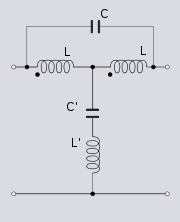
The bridged-T delay equaliser is an electrical all-pass filter
All-pass filter
An all-pass filter is a signal processing filter that passes all frequencies equally, but changes the phase relationship between various frequencies. It does this by varying its propagation delay with frequency...
circuit utilising bridged-T topology whose purpose is to insert an, ideally, constant delay at all frequencies in the signal path. It is a class of image filter.
Applications
The network is used when it is required that two or more signals are matched to each other on some form of timing criterion. Delay is added to all other signals so that the total delay is matched to the signal which already has the longest delay. In television broadcasting, for instance, it is desirable that the timing of the television waveform synchronisation pulses from different sources are aligned as they reach studio control rooms or network switching centres. This ensures that cuts between sources do not result in disruption at the receivers. Another application occurs when stereophonic soundStereophonic sound
The term Stereophonic, commonly called stereo, sound refers to any method of sound reproduction in which an attempt is made to create an illusion of directionality and audible perspective...
is connected by landline, for instance from an outside broadcast to the studio centre. It is important that delay is equalised between the two stereo channels as a difference will destroy the stereo image
Stereo imaging
Stereo imaging is an audio jargon term used for the aspect of sound recording and reproduction concerning spatial locations of the sound source, both laterally and in depth. An image is 'good' if the performers can be effortlessly located; 'bad' if there is no hope of doing so...
. When the landlines are long and the two channels arrive by substantially different routes it can require many filter sections to fully equalise the delay.
Operation
The operation is best explained in terms of the phase shift the network introduces. At low frequencies L is low impedance and C' is high impedance and consequently the signal passes through the network with no shift in phase. As the frequency increases, the phase shift gradually increases, until at some frequency, ω0, the shunt branch of the circuit, L'C', goes in to resonance and causes the centre-tap of L to be short-circuited to ground. TransformerTransformer
A transformer is a device that transfers electrical energy from one circuit to another through inductively coupled conductors—the transformer's coils. A varying current in the first or primary winding creates a varying magnetic flux in the transformer's core and thus a varying magnetic field...
action between the two halves of L, which had been steadily becoming more significant as the frequency increased, now becomes dominant. The winding of the coil is such that the secondary winding produces an inverted voltage to the primary. That is, at resonance the phase shift is now 180°. As the frequency continues to increase, the phase delay also continues to increase and the input and output start to come back into phase as a whole cycle delay is approached. At high frequencies L and L' approach open-circuit and C approaches short-circuit and the phase delay tends to level out at 360°.
The relationship between phase shift (φ) and time delay (TD) with angular frequency (ω) is given by the simple relation,

It is required that TD is constant at all frequencies over the band of operation. φ must therefore be kept linearly proportional to ω. With suitable choice of parameters, the network phase shift can be made linear up to about 180° phase shift.
Design
The four component values of the network provide four degrees of freedomDegrees of freedom (physics and chemistry)
A degree of freedom is an independent physical parameter, often called a dimension, in the formal description of the state of a physical system...
in the design. It is required from image theory
Image impedance
Image impedance is a concept used in electronic network design and analysis and most especially in filter design. The term image impedance applies to the impedance seen looking in to the ports of a network. Usually a two-port network is implied but the concept is capable of being extended to...
(see Zobel network
Zobel network
Zobel networks are a type of filter section based on the image impedance design principle. They are named after Otto Zobel of Bell Labs who published a much referenced paper on image filters in 1923. The distinguishing feature of Zobel networks is that the input impedance is fixed in the design...
) that the L/C branch and the L'/C' branch are the dual of each other (ignoring the transformer action) which provides two parameters for calculating component values. A third parameter is set by choosing a resonant frequency, this is set to (at least) the maximum frequency the network is required to operate at.
There is one remaining degree of freedom that the designer can use to maximimally linearise the phase/frequency response. This parameter is usually stated as the L/C ratio. As stated above, it is not practical to linearise the phase response above 180°, ie half a cycle, so once a maximum frequency of operation, fm is chosen, this sets the maximum delay that can be designed in to the circuit and is given by,

For broadcast sound purposes, 15 kHz is often chosen as the maximum usable frequency on landlines. A delay equaliser designed to this specification can therefore insert a delay of 33μs. In reality, the differential delay that might be required to equalise may be many hundreds of microseconds. A chain of many sections in tandem will be required. For television purposes, a maximum frequency of 6 MHz might be chosen, which corresponds to a delay of 83ns. Again, many sections may be required to fully equalise. In general, much greater attention is paid to the routing and exact length of television cables because many more equaliser sections are required to remove the same delay difference as compared to audio.
See also
- All-pass filterAll-pass filterAn all-pass filter is a signal processing filter that passes all frequencies equally, but changes the phase relationship between various frequencies. It does this by varying its propagation delay with frequency...
- Lattice phase equaliserLattice phase equaliserA lattice phase equaliser or lattice filter is an example of an all-pass filter. That is, the attenuation of the filter is constant at all frequencies but the relative phase between input and output varies with frequency...
- Bartlett's bisection theoremBartlett's bisection theoremBartlett's Bisection Theorem is an electrical theorem in network analysis due to Albert Charles Bartlett. The theorem shows that any symmetrical two-port network can be transformed into a lattice network...
- Zobel networkZobel networkZobel networks are a type of filter section based on the image impedance design principle. They are named after Otto Zobel of Bell Labs who published a much referenced paper on image filters in 1923. The distinguishing feature of Zobel networks is that the input impedance is fixed in the design...