
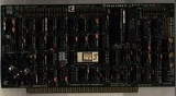
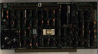
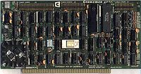
4FDC Floppy Disk Controller
Encyclopedia
Floppy disk controller
A floppy disk controller is a special-purpose chip and associated disk controller circuitry that directs and controls reading from and writing to a computer's floppy disk drive . This article contains concepts common to FDCs based on the NEC µPD765 and Intel 8072A or 82072A and their descendants,...
is designed to interface both 5- and 8-inch floppy disk
Floppy disk
A floppy disk is a disk storage medium composed of a disk of thin and flexible magnetic storage medium, sealed in a rectangular plastic carrier lined with fabric that removes dust particles...
drives to the S-100 computer bus
S-100 bus
The S-100 bus or Altair bus, IEEE696-1983 , was an early computer bus designed in 1974 as a part of the Altair 8800, generally considered today to be the first personal computer...
used in Cromemco
Cromemco
Cromemco was a Mountain View, California microcomputer company known for its high-end Z80-based S-100 bus computers in the early days of the home computer revolution. The Cromemco Dazzler was the first color graphics card available for personal computers....
and other IEEE 696 computers. It also contains an RS232 serial
Serial communications
In telecommunication and computer science, serial communication is the process of sending data one bit at a time, sequentially, over a communication channel or computer bus. This is in contrast to parallel communication, where several bits are sent as a whole, on a link with several parallel channels...
I/O
Input/output
In computing, input/output, or I/O, refers to the communication between an information processing system , and the outside world, possibly a human, or another information processing system. Inputs are the signals or data received by the system, and outputs are the signals or data sent from it...
channel with software-selectable baud
Baud
In telecommunications and electronics, baud is synonymous to symbols per second or pulses per second. It is the unit of symbol rate, also known as baud rate or modulation rate; the number of distinct symbol changes made to the transmission medium per second in a digitally modulated signal or a...
rates from 110 to 76,800. In addition, it has a 1K resident 2708 ROM
Read-only memory
Read-only memory is a class of storage medium used in computers and other electronic devices. Data stored in ROM cannot be modified, or can be modified only slowly or with difficulty, so it is mainly used to distribute firmware .In its strictest sense, ROM refers only...
containing Cromemco's RDOS, the Resident Disk Operating System
Disk operating system
Disk Operating System and disk operating system , most often abbreviated as DOS, refers to an operating system software used in most computers that provides the abstraction and management of secondary storage devices and the information on them...
.
The 4FDC was designed to drive Persci 277 8-inch single-density floppy drives. These drives were interesting in two respects
- They used a fast voice coilVoice coilA voice coil is the coil of wire attached to the apex of a loudspeaker cone. It provides the motive force to the cone by the reaction of a magnetic field to the current passing through it...
actuator and not a stepper motorStepper motorA stepper motor is a brushless, electric motor that can divide a full rotation into a large number of steps. The motor's position can be controlled precisely without any feedback mechanism , as long as the motor is carefully sized to the application...
to position the drive read write head - The data separator electronics were on the drive itself
Due to the second fact, an unmodified 4FDC can not be used with 8-inch drives that don't have single-density data separators on the drive electronics. Later Cromemco disk controllers such as the 16FDC and 64FDC contained both single and double density data separators and the 64FDC also supplied write pre-compensation.
An aftermarket add-on board, the FDCX4 Double Density Upgrade Board for the 4FDC, was designed and marketed by JVB Electronics. The FDCX4 was a daughter board assembly that replaced the WD1771 single density disk controller chip on the 4FDC with a FD1791 (early production) or Fujitsu MB8876A (later production) double-density controller chip. The FDCX4, in addition to using an analog phase-locked-loop data separator in all modes, also used write-precompensation
Write precompensation
Write precompensation is a technical aspect of hard disk design. It is the use of a stronger magnetic field to write data in sectors that are closer to the center of the disk...
. These features allowed the FDCX4 equipped 4FDC to reliably use the Persci 277 drives, as well as other drives, in double-density mode.
Technical Notes
Four switches on the 4FDC interface card are usedto set the operation of the card. Switch 1 is the RDOS
DISABLE switch. When this switch is ON the 1K ROM
containing RDOS cannot be accessed by the computer.
When this switch is OFF the RDOS program resides in
the computer memory
Computer storage
Computer data storage, often called storage or memory, refers to computer components and recording media that retain digital data. Data storage is one of the core functions and fundamental components of computers....
space from address 0xC000 to 0xC3FF.
Switch 2 is the RDOS DISABLE AFTER BOOT switch. If
this switch is ON the 1K ROM containing RDOS will
automatically be disabled after CDOS is bootstrapped
in from a disk thus clearing memory space from
0xC000 to 0xC3FF for system use. (In this mode the ROM
is actually disabled by an output to port 40H which
is done automatically by CDOS). If switch 2 is OFF,
RDOS remains in memory space even after CDOS is loaded.
RDOS contains two programs; 1) the CDOS bootstrap
program and 2) the console monitor program. Switch 3 is
the BOOT ENABLE switch. When this switch is ON the bootstrap
program will execute (thus loading CDOS) without
first entering the monitor program. If this switch is
off, RDOS begins in the console monitor mode permitting
the bootstrap operation or other operations to be performed
under console control.
Switch 4 is the INITIALIZATION INHIBIT switch.
When this switch is ON, diskettes cannot be initialized
under software control thus preventing a "runaway," program
from unintentionally altering the diskette initialization.
This switch must be OFF when initializing diskettes.
Western DigitalWestern DigitalWestern Digital Corporation is one of the largest computer hard disk drive manufacturers in the world. It has a long history in the electronics industry as an integrated circuit maker and a storage products company. Western Digital was founded on April 23, 1970 by Alvin B...
FD1771-1 Interfaces
All signals from the drives are TTLTTL
TTL may refer to:* Taiwan Tobacco and Liquor, a state-owned manufacturer of cigarettes and alcohol in Taiwan* Through-the-lens metering, a feature of cameras capable of measuring light levels in a scene through their lens...
.buffered. and have
150 Ω
Ohm
The ohm is the SI unit of electrical resistance, named after German physicist Georg Simon Ohm.- Definition :The ohm is defined as a resistance between two points of a conductor when a constant potential difference of 1 volt, applied to these points, produces in the conductor a current of 1 ampere,...
pullups. Maxi and mini signals are wired and at
the pullup side of the buffers. Signals which. do not apply
to the mini (i.e. ,.READY and SEP CLOCK), are disabled and
pulled high when the mini is selected.
Signals to the drives from the 1771 are TTL buffered
with separate buffers for mini and. maxi connectors. The
STEP output is stretched by IC37 to about 16 microseconds
before going to the .drives.. The HLD (head load) output does
not go directly to the drives but rather enables the drive
select lines through IC10 Pin1. Thus, the actual drive select
signal to the drive is the coincidence of a latched drive
selection (done at port 34H) and HLD from the 1771. Head
loading time is determined by counters IC36. and 27. timeout is controlled by the count loaded into lC3'S by IC53.
Signals DRQ, HLD, and INTRQ (or EOJ) are available at
input port 34H (rC9). Various control signals are assigned
to output port 34H and are latched by rcs 24 and 41.
Board Priority Chain
The 4FDC includes a ripple priority circuit which willdefeat the interrupt acknowledge cycle of Priority IN/ is
held low. If the 4FDC is allowed to perform the interrupt
acknowledge, it will pull down its Priority Out/ line to
signal others in the chain not to respond. This chain is
compatible with the Cromemco TU-ART.