
Turbine map
Encyclopedia
Each turbine
in a gas turbine
engine has an operating map. Complete maps are either based on turbine rig test results or are predicted by a special computer program. Alternatively, the map of a similar turbine can be suitably scaled.
, but not actual flow. Sometimes the axes of a turbine map are transposed, to be consistent with those of a compressor map
. As in this case, a companion plot, showing the variation of isentropic (i.e. adiabatic
) or polytropic efficiency, is often also included.
In this example the turbine is a transonic unit, where the throat Mach number
reaches sonic
conditions and the turbine becomes truly choked
. Consequently, there is virtually no variation in flow between the corrected speed
lines at high pressure ratios.
Most turbines however, are subsonic devices, the highest Mach number at the NGV throat being about 0.85. Under these conditions, there is a slight scatter in flow between the percent corrected speed lines in the 'choked'
region of the map, where the flow for a given speed reaches a plateau.
Unlike a compressor (or fan), surge (or stall) does not occur in a turbine. This is because the flow through the unit is all 'downhill', from high to low pressure. Consequently there is no surge line marked on a turbine map.
Working lines are difficult to see on a conventional turbine map because the speed lines bunch-up. One trick is to replot the map, with the y-axis being the multiple of flow and corrected speed. This separates the speed lines, enabling working lines (and efficiency contours) to be cross-plotted and clearly seen.
 The following discussion relates to the expansion system of a 2 spool, high bypass ratio, unmixed, turbofan.
On the RHS is a typical primary (i.e. hot) nozzle map (or characteristic). Its appearance is similar to that of a turbine map, but it lacks any (rotational) speed lines. Note that at high flight speeds (ignoring the change in altitude), the hot nozzle is usually in, or close to, a choking condition. This is because the ram rise in the air intake factors-up the nozzle pressure ratio. At static (e.g. SLS) conditions there is no ram rise, so the nozzle tends to operate unchoked (LHS of plot).
The low pressure turbine 'sees' the variation in flow capacity of the primary nozzle. A falling nozzle flow capacity tends to reduce the LP turbine pressure ratio (and deltaH/T). As the left hand map shows, initially the reduction in LP turbine deltaH/T has little effect upon the entry flow of the unit. Eventually, however, the LP turbine unchokes, causing the flow capacity of the LP turbine to start to decrease.
 As long as the LP turbine remains choked, there is no significant change in HP turbine pressure ratio (or deltaH/T) and flow. Once, however, the LP turbine unchokes, the HP turbine deltaH/T starts to decrease. Eventually the HP turbine unchokes, causing its flow capacity to start to fall. Ground Idle is often reached shortly after HPT unchoke.
Turbine
A turbine is a rotary engine that extracts energy from a fluid flow and converts it into useful work.The simplest turbines have one moving part, a rotor assembly, which is a shaft or drum with blades attached. Moving fluid acts on the blades, or the blades react to the flow, so that they move and...
in a gas turbine
Gas turbine
A gas turbine, also called a combustion turbine, is a type of internal combustion engine. It has an upstream rotating compressor coupled to a downstream turbine, and a combustion chamber in-between....
engine has an operating map. Complete maps are either based on turbine rig test results or are predicted by a special computer program. Alternatively, the map of a similar turbine can be suitably scaled.
Description
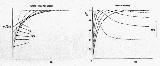
A typical turbine map is shown on the right. In this particular case, lines of percent corrected speed (based on a reference value) are plotted against the x-axis which is pressure ratio, but deltaH/T (roughly proportional to temperature drop across the unit/component entry temperature) is also often used. The y-axis is some measure of flow, usually non-dimensional flow or, as in this case, corrected flowCorrected flow
Corrected Flow is the mass flow that would pass through a device if the inlet pressure and temperature corresponded to ambient conditions at Sea Level, on a Standard Day Corrected Flow is the mass flow that would pass through a device (e.g. compressor, bypass duct, etc.) if the inlet pressure and...
, but not actual flow. Sometimes the axes of a turbine map are transposed, to be consistent with those of a compressor map
Compressor map
Each compressor in a gas turbine engine has an operating map. Complete maps are either based on compressor rig test results or are predicted by a special computer program...
. As in this case, a companion plot, showing the variation of isentropic (i.e. adiabatic
Adiabatic process
In thermodynamics, an adiabatic process or an isocaloric process is a thermodynamic process in which the net heat transfer to or from the working fluid is zero. Such a process can occur if the container of the system has thermally-insulated walls or the process happens in an extremely short time,...
) or polytropic efficiency, is often also included.
In this example the turbine is a transonic unit, where the throat Mach number
Mach number
Mach number is the speed of an object moving through air, or any other fluid substance, divided by the speed of sound as it is in that substance for its particular physical conditions, including those of temperature and pressure...
reaches sonic
Speed of sound
The speed of sound is the distance travelled during a unit of time by a sound wave propagating through an elastic medium. In dry air at , the speed of sound is . This is , or about one kilometer in three seconds or approximately one mile in five seconds....
conditions and the turbine becomes truly choked
Choked flow
Choked flow is a compressible flow effect. The parameter that becomes "choked" or "limited" is the velocity or the mass flow rate.Choked flow is a fluid dynamic condition associated with the Venturi effect...
. Consequently, there is virtually no variation in flow between the corrected speed
Corrected speed
Corrected Speed is the speed a component would rotate at if the inlet temperature corresponded to ambient conditions at Sea Level, on a Standard Day Corrected Speed is the speed a component would rotate at if the inlet temperature corresponded to ambient conditions at Sea Level, on a Standard Day...
lines at high pressure ratios.
Most turbines however, are subsonic devices, the highest Mach number at the NGV throat being about 0.85. Under these conditions, there is a slight scatter in flow between the percent corrected speed lines in the 'choked'
Choked flow
Choked flow is a compressible flow effect. The parameter that becomes "choked" or "limited" is the velocity or the mass flow rate.Choked flow is a fluid dynamic condition associated with the Venturi effect...
region of the map, where the flow for a given speed reaches a plateau.
Unlike a compressor (or fan), surge (or stall) does not occur in a turbine. This is because the flow through the unit is all 'downhill', from high to low pressure. Consequently there is no surge line marked on a turbine map.
Working lines are difficult to see on a conventional turbine map because the speed lines bunch-up. One trick is to replot the map, with the y-axis being the multiple of flow and corrected speed. This separates the speed lines, enabling working lines (and efficiency contours) to be cross-plotted and clearly seen.
Progressive unchoking of the expansion system
On the RHS is a typical primary (i.e. hot) nozzle map (or characteristic). Its appearance is similar to that of a turbine map, but it lacks any (rotational) speed lines. Note that at high flight speeds (ignoring the change in altitude), the hot nozzle is usually in, or close to, a choking condition. This is because the ram rise in the air intake factors-up the nozzle pressure ratio. At static (e.g. SLS) conditions there is no ram rise, so the nozzle tends to operate unchoked (LHS of plot).
The low pressure turbine 'sees' the variation in flow capacity of the primary nozzle. A falling nozzle flow capacity tends to reduce the LP turbine pressure ratio (and deltaH/T). As the left hand map shows, initially the reduction in LP turbine deltaH/T has little effect upon the entry flow of the unit. Eventually, however, the LP turbine unchokes, causing the flow capacity of the LP turbine to start to decrease.