
Translinear circuit
Encyclopedia
A translinear circuit is a circuit that carries out its function using the translinear principle. These are current-mode circuits that can be made using transistors that obey an exponential
current-voltage characteristic—this includes BJTs and CMOS transistors in weak inversion.
The word translinear (TL) was invented by Barrie Gilbert
in 1975 to describe circuits that used the exponential current-voltage relation of BJTs. By using this exponential relationship, this class of circuits can implement multiplication, amplification and power-law relationships. When Barrie Gilbert described this class of circuits he also described the translinear principle (TLP) which made the analysis of these circuits possible in a way that the previous view of BJTs as linear current amplifiers did not allow. TLP was later extended to include other elements that obey an exponential current-voltage relationship (such as CMOS transistors in weak inversion).
The TLP has been used in a variety of circuits including vector arithmetic circuits, current conveyors, current-mode operational amplifier
s, and RMS
-DC converters. It has been in use since the 1960s (by Gilbert), but was not formalized until 1975. In the 1980s, Evert Seevinck's work helped to create a systematic process for translinear circuit design. In 1990 Seevinck invented a circuit he called a companding current-mode integrator that was effectively a first-order log-domain filter. A version of this was generalized in 1993 by Douglas Frey and the connection between this class of filters and TL circuits was made most explicit in the late 90s work of Jan Mulder et al. where they describe the dynamic translinear principle. More work by Seevinck led to synthesis techniques for extremely low-power TL circuits. More recent work in the field has led to the voltage-translinear principle, multiple-input translinear element networks, and field-programmable analog arrays (FPAAs).
The TLP is dependent on the exponential current-voltage relationship of a circuit element. Thus, an ideal TE follows the relationship

where is a pre-exponential scaling current,
  is a dimensionless multiplier to
  ,
,  is a dimensionless multiplier to the gate-emitter voltage and
  is the thermal voltage
  .
.
In a circuit, TEs are described as either clockwise (CW) or counterclockwise (CCW). If the arrow on the emitter point clockwise, it's considered a CW TE, if it points counterclockwise, it's considered a CCW TE. Consider an example:
 By Kirchoff's Voltage Law, the voltage around the loop that goes from
  to
to  must be 0. In other words, the voltage drops must equal the voltage increases. When a loop that only goes through the emitter-gate connections of TEs exists, we call it a translinear loop. Mathematically, this becomes

Because of the exponential current-voltage relationship, this implies TLP:

this is effectively because current is used as the signal. Because of this, voltage is the log of the signal and addition in the log domain is like multiplication of the original signal (ie ). This rule, that the product of the current through CW TEs is equal to the current through CCW TEs in a translinear loop is known as the translinear principle.
For a detailed derivation of the TLP, and physical interpretations of the parameters in the ideal TE law, please refer to or .
A derivation of the TLP based on graph theory concepts has been given by Rafael Vargas-Bernal et al. in 2000. In this work, it is illustrated as a graphical representation can be used for the future development of a verification tool that plays an important and fundamental role in the structured design of translinear circuits.
According to TLP,
 .
.
This means that where
where  is the unit scaling current (ie the definition of unity for the circuit). This is effectively a squaring circuit where
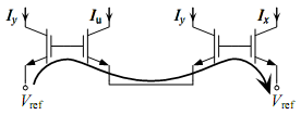
  . This particular circuit is designed in what is known as an alternating topology, which means that CW TEs alternate with CCW TEs. Here's the same circuit in a stacked topology.
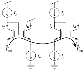
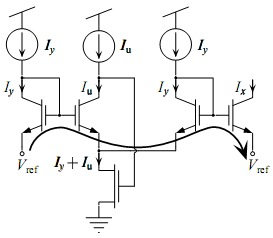
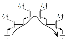 The same equation applies to this circuit as to the alternating topology according to TLP. Neither of these circuits can be implemented in real life without biasing the transistors such that the currents expected to flow through them can actually do so. Here are some example biasing schemes:
A two quadrant multiplier has the relationship hold while allowing
  to be either positive or negative. We'll let
  and
and  . Also note that
  and
and  etc. Plugging these values into the original equation yields
  . This can be rephrased as
  . By equating the positive and negative portions of the equation, two equations that can be directly built as translinear loops arise:


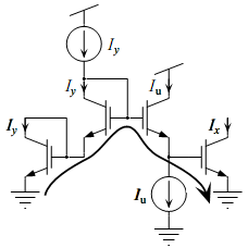
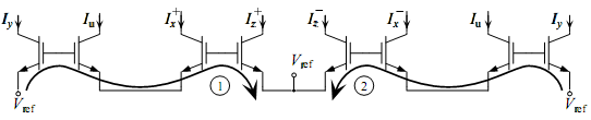
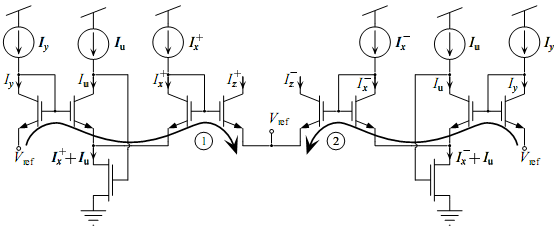
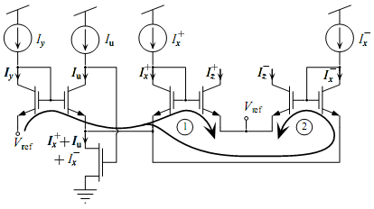
The following are the alternating loops that implement the desired equations and some biasing schemes for the circuit.
Exponential function
In mathematics, the exponential function is the function ex, where e is the number such that the function ex is its own derivative. The exponential function is used to model a relationship in which a constant change in the independent variable gives the same proportional change In mathematics,...
current-voltage characteristic—this includes BJTs and CMOS transistors in weak inversion.
The word translinear (TL) was invented by Barrie Gilbert
Barrie Gilbert
Barrie Gilbert was born in 1937 in Bournemouth, England. He is well-known for his invention of numerous analog circuit concepts, holding over 100 patents worldwide, and for the discovery of the Translinear Principle and a class of related topologies loosely referred to as the Gilbert cell, one of...
in 1975 to describe circuits that used the exponential current-voltage relation of BJTs. By using this exponential relationship, this class of circuits can implement multiplication, amplification and power-law relationships. When Barrie Gilbert described this class of circuits he also described the translinear principle (TLP) which made the analysis of these circuits possible in a way that the previous view of BJTs as linear current amplifiers did not allow. TLP was later extended to include other elements that obey an exponential current-voltage relationship (such as CMOS transistors in weak inversion).
The TLP has been used in a variety of circuits including vector arithmetic circuits, current conveyors, current-mode operational amplifier
Operational amplifier
An operational amplifier is a DC-coupled high-gain electronic voltage amplifier with a differential input and, usually, a single-ended output...
s, and RMS
RMS
-Science and technology:* Root mean square, a concept encapsulating the "average", in some sense, of a quantity. Frequently encountered in statistics, the physical sciences and electronics...
-DC converters. It has been in use since the 1960s (by Gilbert), but was not formalized until 1975. In the 1980s, Evert Seevinck's work helped to create a systematic process for translinear circuit design. In 1990 Seevinck invented a circuit he called a companding current-mode integrator that was effectively a first-order log-domain filter. A version of this was generalized in 1993 by Douglas Frey and the connection between this class of filters and TL circuits was made most explicit in the late 90s work of Jan Mulder et al. where they describe the dynamic translinear principle. More work by Seevinck led to synthesis techniques for extremely low-power TL circuits. More recent work in the field has led to the voltage-translinear principle, multiple-input translinear element networks, and field-programmable analog arrays (FPAAs).
The Translinear Principle
The translinear principle is that in a closed loop containing an even number of translinear elements (TEs) with an equal number of them arranged clockwise and counter-clockwise, the product of the currents through the clockwise TEs equals the product of the currents through the counter-clockwise TEs orThe TLP is dependent on the exponential current-voltage relationship of a circuit element. Thus, an ideal TE follows the relationship
where
is a pre-exponential scaling current, is a dimensionless multiplier to , is a dimensionless multiplier to the gate-emitter voltage and is the thermal voltage .In a circuit, TEs are described as either clockwise (CW) or counterclockwise (CCW). If the arrow on the emitter point clockwise, it's considered a CW TE, if it points counterclockwise, it's considered a CCW TE. Consider an example:
to must be 0. In other words, the voltage drops must equal the voltage increases. When a loop that only goes through the emitter-gate connections of TEs exists, we call it a translinear loop. Mathematically, this becomesBecause of the exponential current-voltage relationship, this implies TLP:
this is effectively because current is used as the signal. Because of this, voltage is the log of the signal and addition in the log domain is like multiplication of the original signal (ie
). This rule, that the product of the current through CW TEs is equal to the current through CCW TEs in a translinear loop is known as the translinear principle.For a detailed derivation of the TLP, and physical interpretations of the parameters in the ideal TE law, please refer to or .
A derivation of the TLP based on graph theory concepts has been given by Rafael Vargas-Bernal et al. in 2000. In this work, it is illustrated as a graphical representation can be used for the future development of a verification tool that plays an important and fundamental role in the structured design of translinear circuits.
Squaring Circuit
.This means that
where is the unit scaling current (ie the definition of unity for the circuit). This is effectively a squaring circuit where . This particular circuit is designed in what is known as an alternating topology, which means that CW TEs alternate with CCW TEs. Here's the same circuit in a stacked topology.2-Quadrant Multiplier
The design of a 2-quadrant multiplier can be easily done using TLP. The first issue with this circuit is that negative values of currents need to be represented. Since all currents must be positive for the exponential relationship to hold (the log operation is not defined for negative numbers), positive currents must represent negative currents. The way this is done is by defining two positive currents whose difference is the current of interest.A two quadrant multiplier has the relationship
hold while allowing to be either positive or negative. We'll let and . Also note that and etc. Plugging these values into the original equation yields . This can be rephrased as . By equating the positive and negative portions of the equation, two equations that can be directly built as translinear loops arise:The following are the alternating loops that implement the desired equations and some biasing schemes for the circuit.