
Tower Mounted Amplifier
Encyclopedia
Low-noise amplifier
Low-noise amplifier is an electronic amplifier used to amplify possibly very weak signals . It is usually located very close to the detection device to reduce losses in the feedline. This active antenna arrangement is frequently used in microwave systems like GPS, because coaxial cable feedline is...
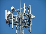
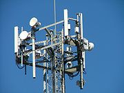
(LNA) mounted as close as practical to the antenna in mobile masts or Base Transceiver Station
Base Transceiver Station
A base transceiver station or cell site is a piece of equipment that facilitates wireless communication between user equipment and a network. UEs are devices like mobile phones , WLL phones, computers with wireless internet connectivity, WiFi and WiMAX gadgets etc...
s. A TMA reduces the base transceiver station noise figure
Noise figure
Noise figure is a measure of degradation of the signal-to-noise ratio , caused by components in a radio frequency signal chain. The noise figure is defined as the ratio of the output noise power of a device to the portion thereof attributable to thermal noise in the input termination at standard...
(NF) and therefore improve its overall sensitivity; in other words the mobile mast is able to receive weaker signals.
Benefits in mobile communications
In two way communicationsTwo-way radio
A two-way radio is a radio that can both transmit and receive , unlike a broadcast receiver which only receives content. The term refers to a personal radio transceiver that allows the operator to have a two-way conversation with other similar radios operating on the same radio frequency...
systems, there are occasions when one way, one link, is weaker than the other, normally referenced as unbalanced links. This can be fixed by making the transmitter on that link stronger or the receiver more sensitive to weaker signals.
TMAs are used in mobile networks to improve the sensitivity of the uplink in mobile phone masts. Since the transmitter is a mobile phone it cannot be easily modified to transmit stronger signals. Improving the uplink translates into a combination of better coverage and mobile transmitting at less power, which in turn implies a lower drain from its batteries, thus a longer battery charge.
There are occasions when the cable between the antenna and the receiver is so lossy (too thin or too long) that the signal weakens from the antenna before reaching the receiver; therefore it may be decided to install TMAs from the start to make the system viable. In other words, the TMA can only partially correct, or palliate, the link imbalance.
Drawbacks/pitfalls
- If the received signal is not weak, installing a TMA will not deliver its intended benefit.
- If the received signal is strong enough, it may cause the TMA to create its own interference which is passed on to the receiver.
- In some mobile networks (e.g. IS-95IS-95Interim Standard 95 is the first CDMA-based digital cellular standard by Qualcomm. The brand name for IS-95 is cdmaOne. IS-95 is also known as TIA-EIA-95....
or WCDMA - aka European 3G3G3G or 3rd generation mobile telecommunications is a generation of standards for mobile phones and mobile telecommunication services fulfilling the International Mobile Telecommunications-2000 specifications by the International Telecommunication Union...
-), it is not simple to detect and correct unbalanced links since the link balance is not constant; link balance changes with traffic load. However, other mobile networks (e.g. GSM) have a constant link, therefore it is possible analyse call records and establish where TMAs are needed.
- There might be practical room restrictions, visual, or structural weight restrictions to install a TMA at the top of a phone mast.
- If the TMA fails, it may render the system unusable until serviced, unless it can be bypassed.
- Servicing TMAs is harder than servicing receivers - and thus more expensive - as the TMA may be dangerously near (near field) of the antenna and high up in a tower. The receiver may alternatively be housed in a cabinet or hut at the base of the tower.
Mathematical principles
In a receiver, the receiving path starts with the signal originating at the antenna. Then the signal is amplified in further stages within the receiver. It is actually not amplified all at once but in stages, with some stages producing other changes (like changing the signal's frequencyFrequency mixer
In electronics a mixer or frequency mixer is a nonlinear electrical circuit that creates new frequencies from two signals applied to it. In its most common application, two signals at frequencies f1 and f2 are applied to a mixer, and it produces new signals at the sum f1 + f2 and difference f1 -...
).
The principle can be demonstrated mathematically; the receiver's noise figure is calculated by modularly assessing each amplifier stage. Each stage consists of a noise figure
Noise figure
Noise figure is a measure of degradation of the signal-to-noise ratio , caused by components in a radio frequency signal chain. The noise figure is defined as the ratio of the output noise power of a device to the portion thereof attributable to thermal noise in the input termination at standard...
(F) and an amount of amplification, or gain (G). So amplifier number 1 will be right after the antenna and described by
 and
and  . The relationship of the stages is known as the Friis formula.
Note that:
- The first amplifier will set the temperature (
 ); nothing reduces its contribution to the total.
 - The second amplifier's temperature (
 ) will also influence the total but it is reduced (divided) by the gain of the first amplifier
  .
. - The third amplifier's temperature is influencing even less, as it is reduced by its preceding amplifier gains
 ,
,  .
. - And so on until N stages.
Typical receiver without TMA
Start with a typical receiver: Antenna - Connecting Cable (stage 1) - Receiver (stage 2).
The first stage after the antenna is actually the connecting cable. Therefore:
- Stage 1:
 is equal to the loss of the cable and will increase with ambient temperature
 - Stage 2:
 will depend on the lossiness of the cable. Since the element is lossy
  is less than one; in order words, it will increase
  . The more loss, the closer
  is to zero and the more
  will increase.
What can be done to improve the receiver to pick up very weak signals? It must have a lower noise figure; that is when the TMA comes into use.
Typical receiver with TMA
It is a chain of 4 modules: antenna - short connecting cable (stage 1) - TMA (stage 2) - longer connecting cable (stage 3) - receiver (stage 4)- Stage 1: By using the shortest, the least lossy connecting cable between the antenna and the TMA,
 is low
 is nearly one.
 - Stage 2: The TMA of noise figure
 and gain
  .
. - Stage 3: Then comes the next cable (
 and
and  ), but this time its noise addition (
 ) is reduced by
  .
. - Stage 4: Then comes the receiver, whose noise figure is less downgraded by the cables, as
 ,
,  is from the TMA,
  and from the second cable. So
  will counteract the effects of
  .
.
Updating the Friis formula with this case, the noise figure is now:

In this way, the cable losses are now negligible and do not significantly affect the system noise figure.
This number is normally expressed in decibels (dB) thus:
