

Short Baseline Acoustic Positioning System
Encyclopedia
A Short Baseline Acoustic Positioning System is one of three broad classes of underwater acoustic positioning systems
that are used to track underwater vehicles and divers. The other two classes are Ultra Short Baseline Systems (USBL)
and Long Baseline Systems (LBL)
. Like USBL systems, SBL systems do not require any seafloor mounted transponders or equipment and are thus suitable for tracking underwater targets from boats or ships that are either anchored or under way. However, unlike USBL systems, which offer a fixed accuracy, SBL positioning accuracy improves with transducer spacing. Thus, where space permits, such as when operating from larger vessels or a dock, the SBL system can achieve a precision and position robustness that is similar to that of sea floor mounted LBL systems, making the system suitable for high-accuracy survey work. When operating from a smaller vessel where transducer spacing is limited (i.e. when the baseline is short), the SBL system will exhibit reduced precision.
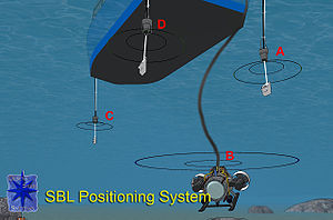 Short baseline systems determine the position of a tracked target such as a ROV by measuring the target's distance from three or more transducers that are, for example, lowered over the side of the surface vessel from which tracking operations take place. These range measurements, which are often supplemented by depth data from a pressure sensor, are then used to triangulate the position of the target. In figure 1, baseline transducer (A) sends a signal, which is received by a transponder (B) on the tracked target. The transponder replies, and the reply is received by the three baseline trasducers (A, C, D). Signal run time measurements now yield the distances B-A, B-C and B-D. The resulting target positions are always relative to the location of the baseline transducers. In cases where tracking is conducted from a moving boat but the target position must be known in earth coordinates such as latitude/longitude or UTM, the SBL positioning system is combined with a GPS receiver and an electronic compass, both mounted on the boat. These instruments determine the location and orientation of the boat, which are combined with the relative position data from the SBL system to establish the position of the tracked target in earth coordinates.
Short baseline systems get their name from the fact that the spacing of the baseline transducers (on a boat for example) is usually much less than the distance to the target, such as a robotic vehicle or diver venturing far from the boat As with any acoustic positioning system, a larger baseline yields better positioning accuracy. SBL systems use this concept to an advantage by adjusting transducer spacing for best results When operating from larger ships, from docks or from the sea ice where greater transducer spacing can be used, SBL systems can yield a positioning accuracy and robustness approaching that of sea-floor mounted LBL systems.
to the wreck site of the American nuclear submarine USS Thresher
. However, performance was still so poor that out of ten search dives by Trieste 1, visual contact was only made once with the wreckage.
The Woods Hole Oceanographic Institution is using a SHARPS SBL system to guide their JASON tethered deep ocean robotic vehicle relative to the MEDEA depressor weight and docking station associated with the vehicle. Rather than tracking both vehicles with a positioning system from the surface which would result in degraded accuracy as the pair's deployment distance , the SBL baseline transducers are mounted on MEDEA. yielding the position of JASON relative to MEDEA with good accuracy independent of the system's deployment depth. The reported accuracy is 0.09m
 An illustrative use of SBL technology is currently (since 2007) underway in Antarctica, where the Moss Landing Marine Laboratory
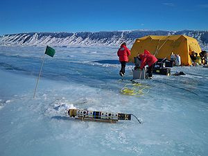
is using a PILOT SBL system to guide the SCINI remotely operated vehicle. SCINI (figure 2) is a small, torpedo-shaped tethered vehicle (ROV
) designed for rapid and uncomplicated deployment and exploration of remote sites around Antarctica, including Heald Island
, Cape Evans
and Bay of Sails. SCINI system is designed to be compact and light-weight so as to facilitate rapid deployment by helicopter, tracked vehicle and even man-hauled sleds. Once on site, its torpedo shaped body allows it to access the ocean through small (20 cm dia.) holes drilled into the sea ice. The mission's science goals however demand high accuracy in navigation, to support tasks including running 10-m video transects (straight lines), providing precise positions for still images to document the distribution and population density of benthic organisms and marking and re-visiting sites for further investigation.
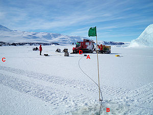
The SBL navigation system (figure 3) consists of three small, 5 cm diameter sonar baseline transducers (A, B, C) that are linked by cable to a control box (D). A small (13.5 cm L x 4 cm D), cylinder shaped transponder is mounted on the SCINI vehicle. Accuracy is optimized by making use of the flat sea ice to place the baseline transducers well apart; approx. 35m for most SCINI deployments.
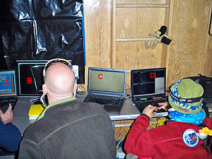
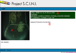
Figure 4 reviews SCINI operations guided by the SBL system. Figure 4A is an improvised ROV control room, in this case in a cabin hauled on top of an ice hole at Cape Armitage. From left, the displays are the ROV controls screen (A), the main camera view (B), the navigation screen (C) and the science display (D). The ROV pilot will generally watch the main camera view. He will glance at the navigation screen (C), which shows the current ROV position and track overlaid on a chart, for orientation and to guide the ROV to the location instructed by the scientist. The scientist, shown here seated on the right is provided with the science display (D), which combines the ROV imagery with position, depth and time data in real time. The scientist types written or speaks audible observations into the computer to provide a context for the data, note objects or evens of interest or designate the start or conclusion of a video transect (figure 4B).
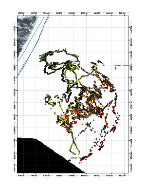
A typical investigation of a site will span several dives, as tasks such as initial investigation, still image acquisition and video transects are gradually completed. A critical element in these dive series is to show prior-dive search coverage, so that a successive dive can be targeted at a previously unvisited area. This is done by producing a cumulative coverage plot of the dive site (figure 4C). The plot, which is updated after every dive, is displayed as a background map on the navigation screen thus providing guidance for the ongoing dive. It shows the prior ROV tracks with color used to indicate depth. Analysis of the track data displayed here yields the quality of positioning to provide a margin of error for measurements. In this case, the typical precision has been established as 0.54m.
Underwater Acoustic Positioning System
An underwater acoustic positioning system is a system for the tracking and navigation of underwater vehicles or divers by means of acoustic distance and/or direction measurements, and subsequent position triangulation...
that are used to track underwater vehicles and divers. The other two classes are Ultra Short Baseline Systems (USBL)
Ultra-short baseline
USBL is a method of underwater acoustic positioning. A complete USBL system consists of a transceiver, which is mounted on a pole under a ship, and a transponder/responder on the seafloor, a towfish, or on a ROV...
and Long Baseline Systems (LBL)
Long Baseline Acoustic Positioning System
A Long Baseline Acoustic Positioning System is one of three broad classes of underwater acoustic positioning systems that are used to track underwater vehicles and divers. The other two classes are Ultra Short Baseline Systems and Short Baseline Systems...
. Like USBL systems, SBL systems do not require any seafloor mounted transponders or equipment and are thus suitable for tracking underwater targets from boats or ships that are either anchored or under way. However, unlike USBL systems, which offer a fixed accuracy, SBL positioning accuracy improves with transducer spacing. Thus, where space permits, such as when operating from larger vessels or a dock, the SBL system can achieve a precision and position robustness that is similar to that of sea floor mounted LBL systems, making the system suitable for high-accuracy survey work. When operating from a smaller vessel where transducer spacing is limited (i.e. when the baseline is short), the SBL system will exhibit reduced precision.
Method of Operation and Performance Characteristics
Figure 1 describes the general method of operation of a short baseline system system.Short baseline systems get their name from the fact that the spacing of the baseline transducers (on a boat for example) is usually much less than the distance to the target, such as a robotic vehicle or diver venturing far from the boat As with any acoustic positioning system, a larger baseline yields better positioning accuracy. SBL systems use this concept to an advantage by adjusting transducer spacing for best results When operating from larger ships, from docks or from the sea ice where greater transducer spacing can be used, SBL systems can yield a positioning accuracy and robustness approaching that of sea-floor mounted LBL systems.
History and Examples of Use
SBL systems are found employed in a variety of often specialized applications. Perhaps the first implementation of any underwater acoustic positioning system was a SBL system installed on the U.S. Navy oceanographic vessel USNS Mizar. In 1963, this system guided the bathyscape Trieste 1Bathyscaphe Trieste
The Trieste is a Swiss-designed, Italian-built deep-diving research bathyscaphe with a crew of two, which reached a record maximum depth of about , in the deepest known part of the Earth's oceans, the Challenger Deep, in the Mariana Trench near Guam, on January 23, 1960, crewed by Jacques Piccard ...
to the wreck site of the American nuclear submarine USS Thresher
USS Thresher (SSN-593)
The second USS Thresher was the lead ship of her class of nuclear-powered attack submarines in the United States Navy. Her loss at sea during deep-diving tests in 1963 is often considered a watershed event in the implementation of the rigorous submarine safety program SUBSAFE.The contract to build...
. However, performance was still so poor that out of ten search dives by Trieste 1, visual contact was only made once with the wreckage.
The Woods Hole Oceanographic Institution is using a SHARPS SBL system to guide their JASON tethered deep ocean robotic vehicle relative to the MEDEA depressor weight and docking station associated with the vehicle. Rather than tracking both vehicles with a positioning system from the surface which would result in degraded accuracy as the pair's deployment distance , the SBL baseline transducers are mounted on MEDEA. yielding the position of JASON relative to MEDEA with good accuracy independent of the system's deployment depth. The reported accuracy is 0.09m
Example of SBL System Use: Under-The-Ice Surveying by ROV in Antarctica
Moss Landing Marine Laboratories
The Moss Landing Marine Laboratories is a multi-campus marine research consortium headquartered at Moss Landing, California.-Organization:...
is using a PILOT SBL system to guide the SCINI remotely operated vehicle. SCINI (figure 2) is a small, torpedo-shaped tethered vehicle (ROV
Rov
Rov is a Talmudic concept which means the majority.It is based on the passage in Exodus 23;2: "after the majority to wrest" , which in Rabbinic interpretation means, that you shall accept things as the majority....
) designed for rapid and uncomplicated deployment and exploration of remote sites around Antarctica, including Heald Island
Heald Island
Heald Island is an island, 3 miles long and 555 m high, which projects through the ice of the Koettlitz Glacier just east of Walcott Bay, in Victoria Land. It was discovered and named by the Discovery expedition for Seaman William L. Heald, a member of the expedition who saved the life of Ferrar...
, Cape Evans
Cape Evans
Cape Evans is a rocky cape on the west side of Ross Island, forming the north side of the entrance to Erebus Bay.The cape was discovered by the Discovery expedition under Robert Falcon Scott, who named it the Skuary. Scott's second expedition, the British Antarctic Expedition , built its...
and Bay of Sails. SCINI system is designed to be compact and light-weight so as to facilitate rapid deployment by helicopter, tracked vehicle and even man-hauled sleds. Once on site, its torpedo shaped body allows it to access the ocean through small (20 cm dia.) holes drilled into the sea ice. The mission's science goals however demand high accuracy in navigation, to support tasks including running 10-m video transects (straight lines), providing precise positions for still images to document the distribution and population density of benthic organisms and marking and re-visiting sites for further investigation.
The SBL navigation system (figure 3) consists of three small, 5 cm diameter sonar baseline transducers (A, B, C) that are linked by cable to a control box (D). A small (13.5 cm L x 4 cm D), cylinder shaped transponder is mounted on the SCINI vehicle. Accuracy is optimized by making use of the flat sea ice to place the baseline transducers well apart; approx. 35m for most SCINI deployments.
Figure 4 reviews SCINI operations guided by the SBL system. Figure 4A is an improvised ROV control room, in this case in a cabin hauled on top of an ice hole at Cape Armitage. From left, the displays are the ROV controls screen (A), the main camera view (B), the navigation screen (C) and the science display (D). The ROV pilot will generally watch the main camera view. He will glance at the navigation screen (C), which shows the current ROV position and track overlaid on a chart, for orientation and to guide the ROV to the location instructed by the scientist. The scientist, shown here seated on the right is provided with the science display (D), which combines the ROV imagery with position, depth and time data in real time. The scientist types written or speaks audible observations into the computer to provide a context for the data, note objects or evens of interest or designate the start or conclusion of a video transect (figure 4B).
A typical investigation of a site will span several dives, as tasks such as initial investigation, still image acquisition and video transects are gradually completed. A critical element in these dive series is to show prior-dive search coverage, so that a successive dive can be targeted at a previously unvisited area. This is done by producing a cumulative coverage plot of the dive site (figure 4C). The plot, which is updated after every dive, is displayed as a background map on the navigation screen thus providing guidance for the ongoing dive. It shows the prior ROV tracks with color used to indicate depth. Analysis of the track data displayed here yields the quality of positioning to provide a margin of error for measurements. In this case, the typical precision has been established as 0.54m.