

Composite structure diagram
Encyclopedia
Composite structure diagram in the Unified Modeling Language
(UML) is a type of static structure diagram, that shows the internal structure of a class
and the collaborations that this structure makes possible.
This diagram can include internal parts, ports through which the parts interact with each other or through which instances of the class interact with the parts and with the outside world, and connectors between parts or ports. A composite structure is a set of interconnected elements that collaborate at runtime to achieve some purpose. Each element has some defined role in the collaboration.
The composite structure diagram and related notions have been introduced into UML2.0 to supplement already existing artifacts such as classes. However the usage of these constructs by engineers and/or modellers is not always in the spirit of inventors of these constructs. A number of additional interpretations develop which are not always consistent with the intended usage of the structure nor with the language itself. Understanding these additional usages assists in understanding areas of ambiguity, extension, inconsistency and the future development of the language.
As tools become more UML compliant and support more UML constructs, engineers and/or modellers begin to use these additional constructs. The effect of this is that the semantics of these constructs is often learnt through an implicit process based around the name of the construct and what the tool appears to allow; in practice, the semantics are often based on the engineer’s expectations and perceived meaning rather than on the actual, intended semantics.
A composite structure diagram always shows the internal structure of a given system and depends upon the internal parts that are used in that particular system. The role of the diagram is to act as a container for the interaction points of various elements of the system and to demonstrate their configuration and relationships.
 The key composite structure entities identified in the UML 2.0 specification are structured classifiers, parts, ports, connectors, and collaborations.
This UML 2.0 composite structure diagram specifies that instances of the 'FibonacciSystem' class are composed of a number of parts. The topmost of these parts is identified as having the classifier 'FibonacciFunction'. Three of the parts are identified by the role they play within instances of FibonacciSystem - the NMinus2 role, the NMinus1 role, and the N role. The fifth part, identified by its classifier Viewer, includes a multiplicity specification. At runtime there can be 0 or more instances of Viewer or some concrete subclass of Viewer.
At runtime the class instances that implement these three roles must provide the services specified by the IVar interface through their var ports. One such class is Variable, shown on the diagram with a port named var of type Var that realizes the IVar interface.
The port named "view" is a non-public port that can be used by an instance of FibonacciSystem to access the optional instance(s) of Viewer.
Unified Modeling Language
Unified Modeling Language is a standardized general-purpose modeling language in the field of object-oriented software engineering. The standard is managed, and was created, by the Object Management Group...
(UML) is a type of static structure diagram, that shows the internal structure of a class
Class (computer science)
In object-oriented programming, a class is a construct that is used as a blueprint to create instances of itself – referred to as class instances, class objects, instance objects or simply objects. A class defines constituent members which enable these class instances to have state and behavior...
and the collaborations that this structure makes possible.
This diagram can include internal parts, ports through which the parts interact with each other or through which instances of the class interact with the parts and with the outside world, and connectors between parts or ports. A composite structure is a set of interconnected elements that collaborate at runtime to achieve some purpose. Each element has some defined role in the collaboration.
The composite structure diagram and related notions have been introduced into UML2.0 to supplement already existing artifacts such as classes. However the usage of these constructs by engineers and/or modellers is not always in the spirit of inventors of these constructs. A number of additional interpretations develop which are not always consistent with the intended usage of the structure nor with the language itself. Understanding these additional usages assists in understanding areas of ambiguity, extension, inconsistency and the future development of the language.
As tools become more UML compliant and support more UML constructs, engineers and/or modellers begin to use these additional constructs. The effect of this is that the semantics of these constructs is often learnt through an implicit process based around the name of the construct and what the tool appears to allow; in practice, the semantics are often based on the engineer’s expectations and perceived meaning rather than on the actual, intended semantics.
A composite structure diagram always shows the internal structure of a given system and depends upon the internal parts that are used in that particular system. The role of the diagram is to act as a container for the interaction points of various elements of the system and to demonstrate their configuration and relationships.
Composite structure concepts
- Part : A part represents a role played at runtime by one instance of a class or by a collection of instances. The part may only name the role, it may name an abstract superclass, or it may name a specific concrete class. The part can include a multiplicity factor, such as the [0..*] shown for Viewer in the diagram.
- A part is like small element in the Composite Structure Diagram, which is set of some instances those are under control of the classifier instance. A part can be deleted from its parent node or bigger part before that bigger part ( parent ) deleted, so it is clear that part is not deleted at the same time when parent deletion is going on.
- Representation - A part is represented as normal rectangle in the composite structure diagram, which is not any kind of decoration with something to increase its beauty or distinction.
- An EncapsulatedClassifier is a type of structured classifier that contains ports. In the diagram above, both FibonacciSystem and Variable are encapsulated classifiers because they both have ports along their boundaries.
- Port : Port is another notation used in the Composite Structure Diagram, which is mainly used for the representation of the externally visible parts of the specified classifiers. Another use of the port is to indicate the relation between the specified classifier and its respected environment. Port is indicated on the boundaries of the composite structures or the classes.
- Representation - A port is represented as rectangle on the boundary of the classifier or that specific subsection.
- Interfaces : Actually interfaces are used for indicating general operations, which has some kind of restrictions and it really looks similar to the classes. It has not any default implementation. It can be public and abstract. Furthermore interfaces are divided into 2 categories such as provided and required interfaces.
-
- Provided interfaces : It says as yes for respected classifier supplies the operations defined by the named interface element, which is mostly defined by drawing a realization link between the class and the interface.
- Required interfaces : It is just like classifier that can communicate with other classifier for providing operations defined by the named interface element.
- Attributes of the interface must be constant. A class can have multiple interfaces.
- Representation - When interface indicated in the diagram as rectangle, it must have <
> keyword. Otherwise it is shown as circle, which indicate the abstract. When interface indicated as the circle, it can not show the operations.
- Delegate : Delegates are used for representing internal working operation like outer interfaces and ports of the respected component. It is kind of connection between the external operation of the component, which is shown by its ports to the internal realization of the behavior of the component's part.
- Representation : It is represented as an arrow, but with the <
> keyword.
- Collaboration : Collaboration used in this scenario for describing the collective efforts taken by the class. It is just like the set of the co-operating operations used collectively to perform any specific task.
- Collaboration mainly used for the describing the roles and attributes to perform any kind of specific task. Re-usability, clarifying the behavior of the system and simplifying the structure are the primary goals of the Collaboration.
- Representation - It can be represented as ellipse in the diagram.
- Role Binding : The main purpose of this role binding is to indicate the classifier that fulfills the role. It is generally directed from the collaboration to the classifier.
- Representation - It is dashed line with the specified role of the classifier. It also has arrowhead to indicate the direction.
- Represents : For indicating collaboration is used in any function or any classifier, another notation "represents" connector drawn from a collaboration to a classifier.
- Representation It is represented as dashed line with arrowhead. It must have the keyword «represents».
Composite structure diagram example
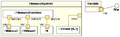
As an example, consider one possible way of modeling production of the Fibonacci sequence.This UML 2.0 composite structure diagram specifies that instances of the 'FibonacciSystem' class are composed of a number of parts. The topmost of these parts is identified as having the classifier 'FibonacciFunction'. Three of the parts are identified by the role they play within instances of FibonacciSystem - the NMinus2 role, the NMinus1 role, and the N role. The fifth part, identified by its classifier Viewer, includes a multiplicity specification. At runtime there can be 0 or more instances of Viewer or some concrete subclass of Viewer.
At runtime the class instances that implement these three roles must provide the services specified by the IVar interface through their var ports. One such class is Variable, shown on the diagram with a port named var of type Var that realizes the IVar interface.
The port named "view" is a non-public port that can be used by an instance of FibonacciSystem to access the optional instance(s) of Viewer.
External links
- General information on UML including the official UML 2.0 specification. See especially the large section on Composite Structures.
- The Xholon open-source project maintains a set of links having to do with composite structure.
- UML 2 Composite Structure Diagrams