

Coherent diffraction imaging
Encyclopedia
Electron
The electron is a subatomic particle with a negative elementary electric charge. It has no known components or substructure; in other words, it is generally thought to be an elementary particle. An electron has a mass that is approximately 1/1836 that of the proton...
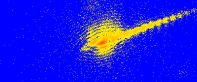
s or other wavelike particle or photon is incident on an object. The beam scattered by the object produces a diffraction pattern downstream which is then collected by a detector. This recorded pattern is then used to reconstruct an image via an iterative feedback algorithm. Effectively, the objective lens in a typical microscope is replaced with software to convert from the reciprocal space diffraction pattern into a real space image. The advantage in using no lenses is that the final image is aberration–free and so resolution is only diffraction and dose limited (dependent on wavelength
Wavelength
In physics, the wavelength of a sinusoidal wave is the spatial period of the wave—the distance over which the wave's shape repeats.It is usually determined by considering the distance between consecutive corresponding points of the same phase, such as crests, troughs, or zero crossings, and is a...
, aperture size and exposure). A simple Fourier transform
Fourier transform
In mathematics, Fourier analysis is a subject area which grew from the study of Fourier series. The subject began with the study of the way general functions may be represented by sums of simpler trigonometric functions...
retrieves only the intensity information and so is insufficient for creating an image from the diffraction pattern due to the phase problem.
The phase problem
There are two relevant parameters for diffracted waves: amplitude and phase. In typical microscopy using lenses there is no phase problem, as phase information is retained when waves are refracted. When a diffraction pattern is collected, the data is described in terms of absolute counts of photons or electrons, a measurement which describes amplitudes but loses phase information. This results in an ill-posed inverse problem as any phase could be assigned to the amplitudes prior to an inverse Fourier transform to real space.Three ideas developed that enabled the reconstruction of real space images from diffraction patterns4. The first idea was the realization by Sayre in 1952 that Bragg diffraction under-samples diffracted intensity relative to Shannon’s theorem. If the diffraction pattern is sampled at twice the Nyquist frequency (inverse of sample size) or lower it can yield a unique real space image². The second was an increase in computing power in the 1980s which enabled iterative Hybrid input output (HIO) algorithm for phase retrieval
Hybrid input output (HIO) algorithm for phase retrieval
Hybrid input-output algorithm for phase retrieval is a modification of the error reduction algorithm for retrieving the phases in Coherent diffraction imaging. Determining the phases of a diffraction pattern is crucial since the diffraction pattern of an object is its Fourier transform and in...
to optimize and extract phase information using adequately sampled intensity data with feedback. This method was introduced3 by Fienup in the 1980s. Finally, the development of “phase recovery” algorithms led to the first demonstration4 of CDI in 1999 by Miao.
Reconstruction
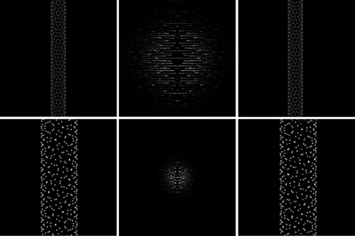
In a typical reconstruction² the first step is to generate random phases and combine them with the amplitude information from the reciprocal space pattern. Then a Fourier transform is applied back and forth to move between real space and reciprocal space with the modulus squared of the diffracted wave field set equal to the measured diffraction intensities in each cycle. By applying various constraints in real and reciprocal space the pattern evolves into an image after enough iterations of the HIO process. To ensure reproducibility the process is typically repeated with new sets of random phases with each run having typically hundreds to thousands of cycles2,8. The constraints imposed in real and reciprocal space typically depend on the experimental setup and the sample to be imaged. The real space constraint is to restrict the imaged object to a confined region called the “support.” For example, the object to be imaged can be initially assumed to reside in a region no larger than roughly the beam size. In some cases this constraint may be more restrictive, such as in a periodic support region for a uniformly spaced array of quantum dots². Other researchers have investigated imaging extended objects, that is, objects that are larger than the beam size, by applying other constraints 12,13.In most cases the support constraint imposed is a priori in that it is modified by the researcher based on the evolving image. In theory this is not necessarily required and algorithms have been developed8 which impose an evolving support based on the image alone using an auto-correlation function. This eliminates the need for a secondary image (support) thus making the reconstruction autonomic.
The diffraction pattern of a perfect crystal is symmetric so the inverse Fourier transform of that pattern is entirely real valued. The introduction of defects in the crystal leads to an asymmetric diffraction pattern with a complex valued inverse Fourier transform. It has been shown7 that the crystal density can be represented as a complex function where its magnitude is electron density and its phase is the “projection of the local deformations of the crystal lattice onto the reciprocal lattice vector Q of the Bragg peak about which the diffraction is measured”3. Therefore, it is possible to image the strain fields associated with crystal defects in 3D using CDI and it has been reported3 in one case. Unfortunately, the imaging of complex-valued functions (which for brevity represents the strained field in crystals) is accompanied by complementary problems namely, the uniqueness of the solutions, stagnation of the algorithm etc. However, recent developments that overcame these problems (particularly for patterned structures) were addressed 10,11.On the other hand, if the diffraction geometry is insensitive to strain, such as in GISAXS, the electron density will be real valued and positive2. This provides another constraint for the HIO process, thus increasing the efficiency of the algorithm and the amount of information that can be extracted from the diffraction pattern.
Coherence
Clearly a highly coherent beam of waves is required for CDI to work since the technique requires interference of diffracted waves. Coherent waves must be generated at the source (synchrotron, field emitter, etc.) and must maintain coherence until diffraction. It has been shown8 that the coherence width of the incident beam needs to be approximately twice the lateral width of the object to be imaged. This result is because Shannon sampling has twice the spatial period of Bragg sampling. As the coherence width is decreased, the size of the Bragg peaks in reciprocal space grows and they begin to overlap leading to decreased image resolution.Diffraction imaging techniques
Coherent x-ray diffraction imaging (CXDI or CXD) uses x-rays (typically .5-4kV)4 to form a diffraction pattern which may be more attractive for 3D applications than electron diffraction since x-rays typically have better penetration. For imaging surfaces, the penetration of X-rays may be undesirable, in which case a glancing angle geometry may be used such as GISAXS2. A typical x-ray CCD is used to record the diffraction pattern. If the sample is rotated about an axis perpendicular to the beam a 3-Dimensional image may be reconstructed³.Due to radiation damage4, resolution is limited (for continuous illumination set-ups) to about 10 nm for frozen-hydrated biological samples but resolutions of as high as 1 to 2 nm should be possible for inorganic materials less sensitive to damage (using modern synchrotron sources). It has been proposed4 that radiation damage may be avoided by using ultra short pulses of x-rays where the time scale of the destruction mechanism is longer than the pulse duration. This may enable higher energy and therefore higher resolution CXDI of organic materials such as proteins. However, without the loss of information “the linear number of detector pixels fixes the energy spread needed in the beam”8 which becomes increasingly difficult to control at higher energies.
In a 2006 report3, resolution was 40 nm using the Advanced Photon Source (APS) but the authors suggest this could be improved with higher power and more coherent X-ray sources such as the X-ray free electron laser.
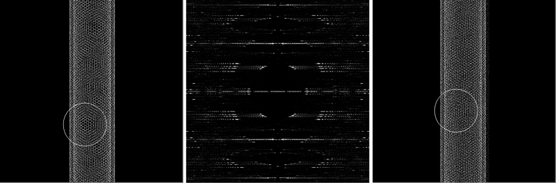
In Zuo’s approach1, a low resolution electron image is used to locate a nanotube. A field emission electron gun generates a beam with high coherence and high intensity. The beam size is limited to nano area with the condenser aperture in order to ensure scattering from only a section of the nanotube of interest. The diffraction pattern is recorded in the far field using electron imaging plates to a resolution of 0.0025 1/Å. Using a typical HIO reconstruction method an image is produced with Å resolution in which the DWCNT chirality (lattice structure) can be directly observed. Zuo found that it is possible to start with non-random phases based on a low resolution image from a TEM
Transmission electron microscopy
Transmission electron microscopy is a microscopy technique whereby a beam of electrons is transmitted through an ultra thin specimen, interacting with the specimen as it passes through...
to improve the final image quality.
Podorov et al. 14 (2007) proposed an exact analytical solution of CDXI problem for particular cases.
See also
- DiffractionDiffractionDiffraction refers to various phenomena which occur when a wave encounters an obstacle. Italian scientist Francesco Maria Grimaldi coined the word "diffraction" and was the first to record accurate observations of the phenomenon in 1665...
- Diffraction TomographyDiffraction TomographyDiffraction tomography is an inverse scattering technique used to find the shape of a scattering object by illuminating it with probing waves and recording the reflections. It is based on the diffraction slice theorem and assumes that the scatterer is weak. It is closely related to X-ray tomography....
- List of materials analysis methods
- NanotechnologyNanotechnologyNanotechnology is the study of manipulating matter on an atomic and molecular scale. Generally, nanotechnology deals with developing materials, devices, or other structures possessing at least one dimension sized from 1 to 100 nanometres...
- Surface Physics
- SynchrotronSynchrotronA synchrotron is a particular type of cyclic particle accelerator in which the magnetic field and the electric field are carefully synchronised with the travelling particle beam. The proton synchrotron was originally conceived by Sir Marcus Oliphant...