
Architectural drawing
Overview
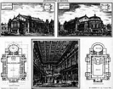
An architectural drawing or architect's drawing is a technical drawing
of a building (or building project) that falls within the definition of architecture
. Architectural drawings are used by architect
s and others for a number of purposes: to develop a design idea into a coherent proposal, to communicate ideas and concepts, to convince clients of the merits of a design, to enable a building contractor to construct it, as a record of the completed work, and to make a record of a building that already exists.
Architectural drawings are drawn according to a set of conventions
, which include particular views (floor plan, section etc.), sheet sizes, units of measurement and scales, annotation and cross referencing.
Technical drawing
Technical drawing, also known as drafting or draughting, is the act and discipline of composing plans that visually communicate how something functions or has to be constructed.Drafting is the language of industry....
of a building (or building project) that falls within the definition of architecture
Architecture
Architecture is both the process and product of planning, designing and construction. Architectural works, in the material form of buildings, are often perceived as cultural and political symbols and as works of art...
. Architectural drawings are used by architect
Architect
An architect is a person trained in the planning, design and oversight of the construction of buildings. To practice architecture means to offer or render services in connection with the design and construction of a building, or group of buildings and the space within the site surrounding the...
s and others for a number of purposes: to develop a design idea into a coherent proposal, to communicate ideas and concepts, to convince clients of the merits of a design, to enable a building contractor to construct it, as a record of the completed work, and to make a record of a building that already exists.
Architectural drawings are drawn according to a set of conventions
Convention (norm)
A convention is a set of agreed, stipulated or generally accepted standards, norms, social norms or criteria, often taking the form of a custom....
, which include particular views (floor plan, section etc.), sheet sizes, units of measurement and scales, annotation and cross referencing.
Unanswered Questions
Discussions