
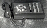
1A2 Key System
Encyclopedia
Analog signal
An analog or analogue signal is any continuous signal for which the time varying feature of the signal is a representation of some other time varying quantity, i.e., analogous to another time varying signal. It differs from a digital signal in terms of small fluctuations in the signal which are...
multiline business key telephone system
Key telephone system
A business telephone system is any of a range of a multiline telephone systems typically used in business environments, encompassing systems ranging from small key systems to large scale private branch....
. Unlike more modern multiline systems, every telephone line
Telephone line
A telephone line or telephone circuit is a single-user circuit on a telephone communication system...
serving a particular phone is wired into that phone, and electromechanical switches (the "keys") switch the lines in the phone itself. The original and largest manufacturer of 1A2 systems was Western Electric
Western Electric
Western Electric Company was an American electrical engineering company, the manufacturing arm of AT&T from 1881 to 1995. It was the scene of a number of technological innovations and also some seminal developments in industrial management...
, later known as AT&T Technologies
AT&T Technologies
AT&T Technologies, Inc., was created in 1983 in preparation for the Bell System Divestiture, which became effective as of January 1, 1984. It assumed the corporate charter of Western Electric Co., Inc.-Creation:...
, Lucent Technologies
Lucent Technologies
Alcatel-Lucent USA, Inc., originally Lucent Technologies, Inc. is a French-owned technology company composed of what was formerly AT&T Technologies, which included Western Electric and Bell Labs...
, and now Avaya
Avaya
Avaya Inc. is a privately held computer networking, information technology and telecommunications company that is a global provider of business communications systems. The international head quarters is in Basking Ridge, New Jersey, United States...
. Compatible 1A2 equipment was also manufactured by a number of vendors including Northern Telecom, and Automatic Electric (GTE
GTE
GTE Corporation, formerly General Telephone & Electronics Corporation was the largest independent telephone company in the United States during the days of the Bell System....
).
Systems that have replaced 1A2 equipment include the AT&T Merlin
AT&T Merlin
The AT&T Merlin telephone system was introduced in late 1983, branded American Bell Merlin. After the breakup of AT&T in 1984, it was rebranded AT&T Merlin. It was designed at the beginning of the 1980s prior to the Bell System Divestiture as a modern electronic replacement for the dated...
, AT&T Spirit, and AT&T Partner systems. These are all now sold and/or serviced by Avaya
Avaya
Avaya Inc. is a privately held computer networking, information technology and telecommunications company that is a global provider of business communications systems. The international head quarters is in Basking Ridge, New Jersey, United States...
.
Components
The earlier 1A2 technology consisted of Key Telephone Systems (Bell Systems Practice 518-215-100). Most Key Telephone Systems at that time (as late as 1980) consisted of key telephone units (KTU) which provided circuit features such as line interface, dial intercom, direct line circuits, etc. Also part of the system were the mounting facilities that hold the KTUs, and power supply. The common telephone sets at that time were the 564 (5-lines), 630 (17 lines), 631 (29-lines), 830 (9-lines), and 831 (19-lines). If the telephone set number started with a '2', such as '2564', then it was Touch-Tone.The power supply
Power supply
A power supply is a device that supplies electrical energy to one or more electric loads. The term is most commonly applied to devices that convert one form of electrical energy to another, though it may also refer to devices that convert another form of energy to electrical energy...
provided 24VDC for relay operation, 24 VDC for talk battery (intercom and direct-line services), 10VAC for lamps, 18 VAC for buzzers, and 90VAC at 20Hz for ringers (Bell System Practice 167-466-101). Lamp and signaling voltages were passed through an interrupter (KS-15900 L1) to create lamp flash (incoming line), lamp wink (hold), and interrupted buzzer and ringing. The mounting facilities varied according to the size and complexity of the Key Telephone System. Typical of early 1A2 systems was the extensive use of 583 and 584-panels to hold the KTUs. The 584C panel contained an interrupter and 13 KTUs. The 583 Panel did not have the interrupter and held 15 KTUs (Bell Systems Practice 518-215-410).
For smaller installations Key System Panels could be purchased that housed all components, including the power supply and connecting blocks. Typically these panels supported only six lines and a dial intercom (Bell System Practice 518-215-424).
Five pairs of wires were required for each line: The central office tip and ring
Tip and ring
"Tip" and "Ring" are common terms in the telephone service industry referring to the two wires or sides of an ordinary telephone line. Tip is the ground side and Ring is the battery side of a phone circuit. In the UK these are referred to as the 'A' and 'B' wires...
, the station (telephone instrument) tip and ring, the A and A1 (control) leads, lamp and lamp ground, and the ring (signaling) pair. The cable to the telephone instrument required fewer pair: station tip and ring, A and A1 pair, and the lamp lead. The lamp ground was only used on the first button, it was not terminated afterward. The Yellow-Slate (grey) pair was usually used for the ringer (Bell System Practice 502-541-407).
Wiring
Each line to the telephone sets was routed using six wires:
- Two wires (one pair) carried the actual telephone line,
- Two wires (a second pair) carried control information (known as 'A-Leads') for that line,
- Two wires (a third pair) carried current to a lamp for the specific line key position on the phone.
A telephone set could contain anywhere from two to over twenty-nine individual telephone lines. Most key telephones (often called 'keysets') with up to nine line positions are connected to the system using a single 25-pair cable
25-pair color code
The 25-pair color code is a color code used to identify individual conductors in a kind of electrical telecommunication wiring for indoor use, known as twisted pair cables . The colors are applied to the insulation that covers each conductor...
and an Amphenol
Amphenol
Amphenol Corporation is a major producer of electronic and fiber optic connectors, cable and interconnect systems such as Coaxial cables. Amphenol is a portmanteau from the corporation's original name, American Phenolic Corp....
50-position "MicroRibbon
Micro ribbon
The micro ribbon or miniature ribbon connector is a common type of electrical connector used particularly in computer and telecommunications applications. Popularly referred to as a Centronics connector due to the widely used Centronics parallel interface, it is also known as a Telco, Amphenol,...
" connector. Keysets with up to 19 line positions used a 50-pair cable, where the big sets with 29 line positions used 75 pairs (three connectors). There was even a 'Call Director' style phone made, at one time, which had over 30 line key positions, and used 100 pairs (four connectors).
Each of the keyset cables was usually run back to the wiring closet, or whatever central location where the KSU had been installed, and terminated on a connection device known as a 66 block
66 block
A 66 block is a type of punchdown block used to connect sets of wires in a telephone system. 66 blocks are designed to terminate 22 through 26 AWG solid copper wire....
or punch block
Punch block
A punch down block is a type of electrical connection often used in telephony. It is named because the solid copper wires are "punched down" into short open-ended slots which are a type of insulation-displacement connectors...
. The blocks most often used to terminate these station cables were the type 66M1-50. Each of these blocks could accept two 25-pair cables (50 pairs, total) for termination.
Cross-connect wire jumpers, consisting of three twisted pairs (the six wires referenced above) would then be run between these blocks and the larger distribution connecting blocks within the KSU.
Very large installations of 1A2 systems had multiple wiring closets fed by branch cables extended from the central closet where the KSU was located. An example of this type of installation would be a multi-story building. The KSU and incoming lines might be in the basement, and each floor would have a branch wiring closet of its own where the phones for that floor were connected.
User interface
A user could select any available phone line simply by pressing the appropriate line button and picking up the handset. A caller could place a call "on hold" by pressing the red "hold" button. Doing so would also mechanically release the depressed line button, allowing the user to select another line.An individual worker or executive might have a set with just a few lines "appearing." The system attendant (receptionist) might have a set with many lines appearing so that they could monitor the status of all incoming lines simultaneously.
These systems also supported manual buzzers, intercom lines (with or without selective ringing), music on hold
Music on hold
Music on hold is the business practice of playing recorded music to fill the silence that would be heard by telephone callers who have been placed on hold...
, and other simple features. The features were provided on a line-by-line basis by the selection of particular Key Telephone Units (KTUs) plugged into a pre-wired backplane
Backplane
A backplane is a group of connectors connected in parallel with each other, so that each pin of each connector is linked to the same relative pin of all the other connectors forming a computer bus. It is used as a backbone to connect several printed circuit boards together to make up a complete...
in the central control unit.
Optional components for the 1A2 could also provide a function called 'I-Hold,' where a call could only be retrieved off hold at the phone that originally placed the line in the hold mode. The cadence of the 'I-Hold' lamp signal was steady illumination punctuated by a series of rapid blinks (produced by a module called a 'flutter generator') every couple of seconds.
Audio
Audible signals (most often ringers or buzzers) could be handled several ways. The first is that the ringer in a specific telephone set could be hardwired to one specific phone line. This had the advantage that the phone would ring any time a call came in on that one line, even during a local power failure, but it also had the disadvantage of limiting ringing to that one line. No other lines could be connected to that ringer without causing problems.The second method, sometimes known as 'common audible,' utilizes the internal circuitry of the KSU's power supply, and circuitry in the individual key telephone units serving each line, to provide a separate and locally-generated ringing signal for each phone line. This has the advantage that you could route the ringing signal for any given line to any phone, or combinations of phones, but it also had the disadvantage of being non-functional during a local power outage.
The third method that was sometimes used because it had the advantages of both of the previous methods, was a combination of the first two methods. A set of relays that were powered by the KSU power supply continuously. The common audible ringing signals from the KSU would run though the energized relays to certain phones that would also ring if there was a power failure. The phone lines that terminated at the KSU were also terminated at these relays and in the event of a power failure, the relays would de-energize and switch the phone lines to the ringers of selected phones.
As for buzzers, they were not usually designed to accommodate the 100 volt/20-30Hz ringing signal used by telephone bells. Instead, they usually took advantage of low-voltage AC (10-18 volts). Unfortunately, this had the same limitation as the second signaling method mentioned above, in that it was not functional during power outages.
Visual
The lamps installed at the telephone sets allowed the user to instantly determine the status of all of the individual telephone lines that "appeared" at that set:- Lamp off — The line is idle
- Lamp steady on — The line is in use for a call
- Lamp flashing slowly (half second on, half second off) — The line is ringing with an incoming call
- Lamp winkingWink pulsingWink is used both in connection with DC signaling on a trunk, and with indicator lamps on a key telephone.In telephone switching systems, wink pulsing is recurring pulsing in which the off-condition is relatively short compared to the on-condition. In Wink start trunks, the exchange at the...
fast — A call on the line is "on hold"
Advantages
The 1A2 system is uncommon today, but some very large installations are still in use due to the high cost of replacing them. There are also several systems in use by collectors of 'vintage' telephone equipment. 1A2 systems are also very popular, still, with radio stations. This is because, being analog, they are easily patchedTelephone hybrid
Telephone hybrids are an essential functional component of the Public Switched Telephone Network . The term also describes the piece of equipment used in broadcast facilities to enable the airing of telephone callers....
into the studio equipment for putting callers on the air.
Unlike most electronic key systems or PBX's, 1A2 systems remain partially functional in the event of a local power failure. The telephones themselves are still able to make and receive calls, assuming the phone company's central office stays alive, but the system is unable to provide any sort of visual (lamps) or audible (buzzers or ringers) signaling during a power outage. The 'Hold' function and intercom services would also be inoperable.
Despite the fact that the 1A2 systems have widely been replaced by more recent electronic key systems or PBX's, the simple and modular design of the 1A2's components provide a degree of versatility and reliability that few of its modern successors can match. This is why 1A2 equipment may be seen in service in places like emergency operations centers, and older police and fire stations.
External links
- Telecommunications Virtual Museum -Retrieved 29 July 2011
- 1A2 Key System explanation -Retrieved 29 July 2011
- The Power of 1A2 -Retrieved 29 July 2011
- 1A2 Key System Advantages -Retrieved 29 July 2011